
Blackmoorfoot Reservoir (2020)
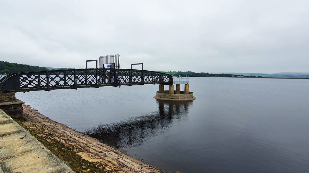
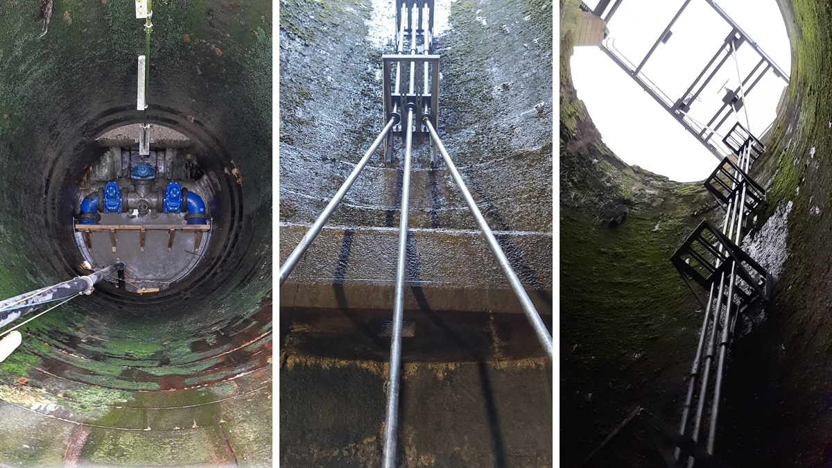
View of Blackmoorfoot Reservoir south overflow/drawdown shaft - Courtesy of Ward & Burke
Blackmoorfoot Reservoir, a storage reservoir situated south-west of Huddersfield in West Yorkshire, was constructed between 1871 and 1876 at a cost of £260,000. It has a capacity of over 700,000 gallons and covers an area of 102 acres and provides raw water to Blackmoorfoot WTW, which supplies treated water to Huddersfield and surrounding areas. The reservoir has two towers designed to provide a service overflow. The 15m deep open-topped south tower/shaft incorporates a 75m long, 1800mm diameter brick tunnel which provides emergency discharge and supplies a full-time compensation flow to the Brows Grain Beck which supplies a feed to the reservoir. The tower is accessed via a metal walkway from the side of the reservoir and a platform sits astride the open top of the shaft.
Project drivers
Incidents in recent years have identified the need for water companies to review the drawdown capacity of their reservoir stock in the event of an emergency. Effective drawdown minimises the potential of dam failure. Under new industry guidelines, all reservoir structures must include adequate drawdown facilities.
Few water companies have done as much as Yorkshire Water in addressing this issue and the works at Blackmoorfoot Reservoir are part of a programme of works across its region.
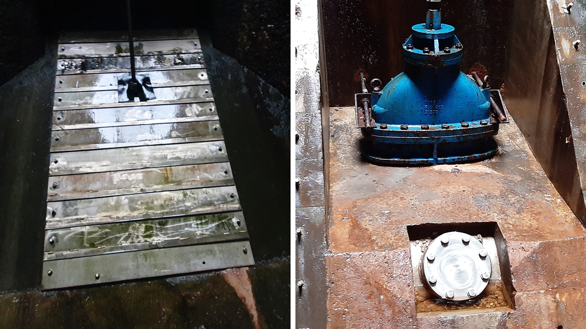
Existing arrangement at the bottom of the south tower – Courtesy of Ward & Burke
Optioneering and design
The initial solution was to meet the requirement was to install 2 (No.) 600mm penstock at two locations midway down the tower which would provide the required drawdown. However, this would have required erecting a barge within the reservoir to situate a crane and install a limpet dam to allow the works to be undertaken from the outside in. Due to the access issue complexity of the work, the budget cost made this approach financially unviable, requiring other options to be investigated.
One option was to keep the penstocks at the location planned with the work being undertaken from within the internals of the tower. This option would require specialised equipment to allow the walls to be cored. The solution was viable from a construction point of view, however as the tower was made from masonry blocks the risk of destabilising the tower (which is resisting a 15m head of water) by coring a number of holes could result in the tower becoming at risk of collapse.
It was noted early in the design review that the solution must not result in a risk to the reservoir or the public as a whole. After lengthy consideration, Yorkshire Water’s reservoir design team proposed a solution to modify the pipework arrangement at the bottom of the shaft to allow for 2 (No.) 450mm diameter outlets which could provide the required drawdown. This solution removed the risk of disturbing the 150 year old shaft, however it posed an issue for the feed of the EA consented compensation flows to Brows Grain which would have to be managed.
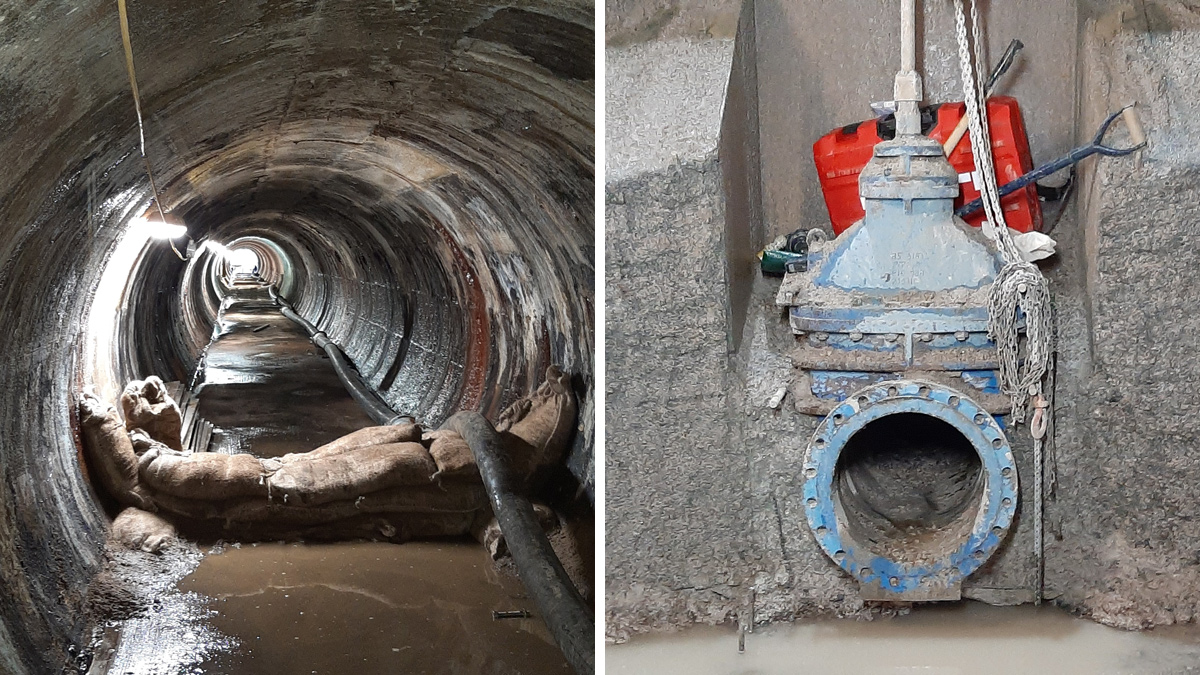
(left) The 1800mm diameter discharge tunnel (and right) to reveal the concrete encased pipework, hydro demolition was used to minimise vibrations – Courtesy of Ward & Burke
Blackmoorfoot Reservoir Increased drawdown capacity: Supply chain – key participants
- Principal contractor: Ward & Burke
- Principal designer: Yorkshire Water and Ward & Burke
- Valve supplier: AVK UK
- Spindle supply and install: Glenfield Invicta
- Diving and underwater cutting services: Northern Divers
Construction of the drawdown
A single gate valve, controlled via a spindle from the platform at the top of the tower, was located at the base of the shaft. The valve-controlled drawdown from a submerged bellmouth inlet pipe. When opened, the valve allows water to flow into 3 (No.) 180mm MDPE pipes which act as the reservoir scour. The valve was accessed via a 75m long tunnel which also acted as the ‘overflow’ in the event of waters overtopping the shaft.
At first glance the works appeared relatively straightforward, using divers to cap off the inlet bellmouth. Prior to this, over pumping for the compensation flows was set up and tested to confirm it provided the minimum required flows. The existing pipework was encased in concrete to provide the required resistance to thrust and it was decided to use hydro demolition methods to minimise the vibrations incurred to the masonry tower.
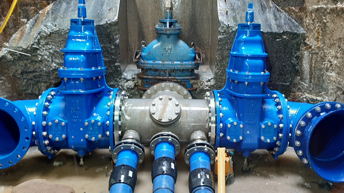
The new pipework arrangement – Courtesy of Ward & Burke
Once broken out, the existing valve was inspected and deemed acceptable to be left in place; this reduced the amount of concrete need to be removed, significantly reducing the associated risks.
A new fabricated manifold that incorporated two further gate valves at right angles to the original valve location were installed. If additional drawdown capacity is needed at any time, these valves will be opened and water will flow out through the tunnel.
AVK UK to supplied two 450mm reservoir specification gate valves, and Ward & Burke appointed Glenfield Invicta to install the associated controls spindles.
Design challenges included how to install the spindles and gearboxes that would link the valves to the controls on the platform 15m above as the design had to ensure minimum loading was applied to the platform itself.
(left) New pipework arrangement and (centre/right) the new spindle arrangement to the top platform – Courtesy of Ward & Burkev
The valve gearboxes were fixed in such a way that they were grouped as closely together as possible. The existing valve was not drilled to accept a gearbox, so this had to be drilled by hand in position. The stem cap had to be carefully cut from the brass stem for the new spindle to be fitted. To comply with current Yorkshire Water specifications, the existing valve needed an input reverse (IR) addition to the input bevel gearboxes (IB3) on top.
The brackets were fabricated from Grade 304 stainless steel due to its corrosion resistance. As each spindle passed through the bracket it was supported by a roller thrust bearing housed within an HDPE carrier fabrication. The brackets were fixed to the shaft sandstone wall using 300mm studding.
The installation team working from temporary scaffolding. Whilst the aim was to install the brackets at regular, fixed centres, the presence of the universal joints, muff couplings, wall surface irregularities and scaffolding meant the installation team used its engineering experience and expertise to locate the fixing points accordingly. The spindles were then connected to the valves at the base and the controls on the platform.
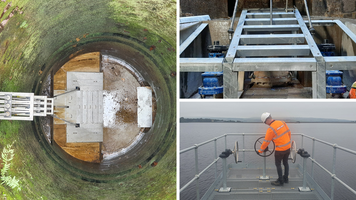
(left and top right) Photos showing the protective platform of new pipework arrangement and (bottom right) the new valve pedestals arrangement to the top platform – Courtesy of Ward & Burke
Once all installation works were completed and tested, the new pipework arrangement at the bottom of the tower needed to be protected from accidental damage and ensure it provided hydraulic assistance to overflow towards the tunnels. Ward & Burke designed and installed protective panels to provide these safeguards.
Completion/handover
The project was successfully completed in February 2020, providing the new requirement of 0.75m of drawdown per day.