
East Tanfield STW (2018)
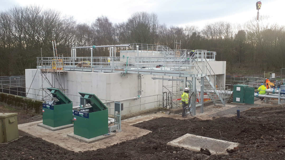
NSAF/DBF constructed within redundant 3m deep humus tanks - Courtesy of MMB
East Tanfield Sewage Treatment Works (STW) is a Northumbrian Water Group (NWG) site located 11 miles north-west of the City of Durham and 9 miles south-west of Newcastle-upon-Tyne. It consists of two distinct sites: a ‘lower’ site comprising a terminal pumping station (TPS) with emergency storage tanks adjacent to the Houghwell Burn watercourse; and an ‘upper’ site comprising an inlet works with flow measurement and control, a screened storm overflow weir, storm tanks, secondary treatment by biological percolating filters, and discharge of treated effluent to the Causey Burn, 520m downstream of the TPS site.
Background
The peak flow arriving at the TPS site was estimated to be 515 l/s (pipe-full capacity) and all flows were pumped to the STW site via a 500mm diameter rising main 1.5km long.
An upgrade was required to meet new discharge consent parameters by the end of March 2018, and improvements were needed to address operation and maintenance issues. Mott MacDonald Bentley (MMB) was appointed in November 2015 to deliver the project under NWG’s AMP6 Design and Construct Framework Runway 2.
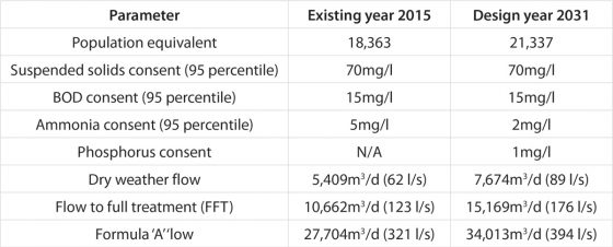
Parameters 2015 and 2031
Project drivers
There were three investment drivers:
- Growth: Catchment growth will increase the contributing population, and there was insufficient process capacity to treat the additional load.
- Quality: New quality consents were coming into force (ammonia and phosphorus) from 31 March 2018 under the National Environment Programme (NEP), requiring new tertiary and chemical treatment plants to achieve compliance. The new plant would also be key to maintaining compliance whilst accommodating development within catchment over the design horizon.
- Maintenance: The operational issues included:
- Increase in screenings and grit arriving at the TPS during storm conditions (contributed to by installation of screens at combined storm overflows) causing frequent pumping system blockages and excessive pump wear.
- At the STW the inlet screens were at capacity, worn and unreliable, allowing passage of rags to the downstream process, causing blockages and compromising distribution chambers and percolating filter distributors, with the potential to affect works compliance. The screenings handling units frequently failed, incurring high reactive maintenance costs.
- Two above-ground steel sludge holding tanks at the STW were corroded and leaking with one being out of service. Decant valves and sludge mixers were inoperable making it impossible to remove top-water with consequent export of sludge with high water content.
Runway 2
NWG’s delivery model for AMP6 projects comprises three ‘Runways’: Runway 1 for high volume short cycle work; Runway 2 for planned work of medium complexity and value, requiring significant design and construction inputs (the majority of schemes in the capital programme); and Runway 3 for bespoke, one-off or complex projects. Under Runway 2, NWG’s asset planners prepare an asset needs statement (ANS) summarising options considered, associated project costs and benefits, to identify a notional solution and set the affordability target.
An Investigate and Define (I&D) contract is then awarded to a framework contractor to: collect further information; review and validate the issues; review and challenge the notional solution and affordability target for efficiencies; define the preferred solution; prepare contract documents and establish a contractual target cost.
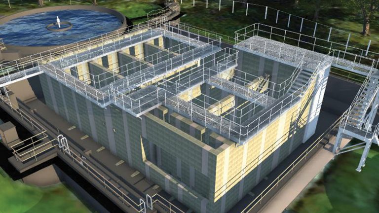
3D model of precast concrete NSAF/DBF plant constructed within redundant rectangular humus tanks – Courtesy of MMB
A core team is established, comprising the NWG project sponsor, asset delivery project manager and operations, and representatives of the MMB design and construction teams. The core team is empowered to make decisions and lead the project through a series of ‘gateways’ to completion. It is incentivised to work collaboratively and share knowledge, to challenge the requirements and the design, and to identify efficiencies.
When a Design and Construct NEC Option C Target Cost contract is agreed, the delivery phase is ‘Good to Go’.
East Tanfield was one of NWG’s first treatment works projects to embark on the AMP6 Runway 2 delivery model. A second project at Pegswood, Northumberland, with a smaller design population of 4,100 (FFT 29l/s) and the same end date, also requiring ammonia removal by NSAF/DBF, commenced after East Tanfield: this allowed commonality of design to be adopted, and lessons learnt to be passed from one design and construct team to the other.
Programme and costs
- The I&D contract for East Tanfield was let in November 2015 and completed in April 2016.
- The D&C contract for East Tanfield was awarded in August 2016 with a target cost of £5.7m: siteworks commenced in October 2016 and flows were turned through the tertiary treatment plant in February 2018.
- The D&C contract for Pegswood was awarded in March 2017 with a target cost of £1.6m. Siteworks commenced in May 2017 and flows were turned in February 2018.
The new tertiary plants at both East Tanfield and Pegswood were commissioned and meeting their new consents by the required end date of 31 March 2018. East Tanfield is generally achieving a final effluent ammonia value of 1mg/l and phosphorous of 0.5mg/l. Pegswood is generally achieving an ammonia value of less than 0.21mg/l, BOD less than 3.5mg/l and suspended solids less than 3.0mg/l.
The existing works
The TPS comprised a consented, but unused, high level combined storm overflow (CSO) immediately upstream of the site with duty/assist/standby drywell-mounted centrifugal pumps forwarding all flows (up to 515 l/s) to the upper site.The STW at the upper site comprised:
- A flow reception chamber, measurement flume, modulating penstock and a weir-mounted storm overflow screen (for flows greater than FFT).
- 2 (No.) rectangular storm tanks, with auto-return and jet-wash cleaning systems.
- A package inlet works comprising 2 (No.) duty/standby automatic fine screens and a grit removal unit.
- 2 (No.) 16m diameter radial flow primary settlement tanks.
- 4 (No.) 44m diameter stone-media percolating biological filters.
- 2 (No.) 19m diameter radial flow humus settlement tanks.
- An MCERTS outlet flow measurement flume.
- A returns liquor pumping station.
- 2 (No.) 12.8m diameter steel sludge holding tanks.
The notional solution
The notional solution was to provide a new inlet works at the lower site to protect the TPS from blockages and excessive pump wear, with duty/assist fine screens, screenings compactors, and grit removal. The pumping station was to be down-rated to forward only FFT to the upper site for treatment.
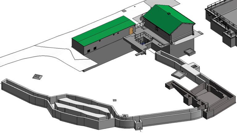
3D model of TPS site showing new inlet works channels, screen channels and detritor – Courtesy of MMB
Flow control and a 3DWF overflow was to be installed after the screens to direct flows in excess of FFT to new storm tanks at the TPS site, the tank contents being returned to the TPS for transfer once the storm had abated.
At the upper site, the notional solution was to: decommission the existing flow control, weir-mounted storm-overflow screen and storm tanks; remove the package inlet works; add chemical dosing (ferric sulphate) for phosphorous removal by precipitation and settlement in the primary tanks; dose sodium hydroxide to correct the pH to a level conducive to subsequent ammonia removal; retain the existing percolating filters for removal of carbonaceous BOD; and add a new interstage pumping station to raise flows from the existing humus tanks to a new tertiary treatment plant for ammonia removal. The tertiary plant would comprise nitrifying submerged aerated filters (NSAF) followed by deep bed filters (DBF) to remove fine solids. The corroded sludge holding tanks were to be replaced and STEM drive mixers added.
Investigate and define (I&D) phase
An assessment of whole-life costs demonstrated that, rather than pumping only FFT from the lower site to the upper site for treatment and building new storm tanks at the lower site, it would be more economical to screen all flows at the lower site, retain the existing storm tanks at the upper site and continue pumping storm flows (but only up to Formula A).
The storage capacity of the existing storm tanks would be increased to provide the new design requirement by raising the outlet weir and peripheral wall height.
The proposal was agreed by the core team. The TPS at the lower site would be provided with: duty/assist automatic fine screens to screen all flows arriving from the catchment; an emergency bypass channel in case of screen failure; a side weir to discharge screened storm flows in excess of Formula A to the Houghwell Burn via the existing CSO outfall; and grit removal by cross-flow detritor for flows being pumped to the upper site. The flow forwarding capacity of the TPS would be reset to transfer the correct Formula A flow.
To allow safer access for more frequent operational traffic and skip wagons, improvements were to be made to the site entrance off the public highway, the access track to the site and the site roads.
The preferred solution of a new inlet works at the lower site meant that the poorly performing screens and grit removal plant at the upper site could be removed. Chemical dosing was confirmed for P-removal, and an NSAF/DBF tertiary treatment plant principally for ammonia removal, although the DBF would also serve to remove further phosphorous. An interstage pumping station would be required to lift flows from the existing humus tanks to the new NSAF.
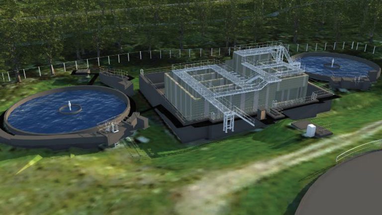
3D model showing NSAF/DBF plant located within redundant rectangular humus tanks – Courtesy of MMB
Options were considered for siting the tertiary plant and it was confirmed that it could be located within disused redundant reinforced concrete rectangular humus tanks, adjacent to the two operational circular humus tanks and the works outfall. The base of the redundant tanks was 3m below existing ground level and founded on mudstone.
This location would realise some significant efficiencies, namely: a disused asset would be brought back into beneficial use; the new pumped feed from the existing humus tanks to the new plant, and the gravity discharge pipework back to the existing outfall would be short; the interstage pumping head, both static lift and friction, would be relatively small, hence smaller pump sizes and lower operating costs; the need for excavation and a temporary cofferdam for construction of the new plant was avoided as the redundant tanks provided the space and depth for construction; no new foundations would be required for the tertiary plant, given the redundant tanks were founded directly on bedrock; and the height above existing ground levels and visual impact of the new plant was reduced from what would have been between 6-8m to only 3-5m.
It became clear that the longest lead item in the construction programme would be the tertiary plant. This would be a sizeable structure containing relatively compact and complex internal baffled chambers and cantilevered channels. An in situ concrete design would have incurred significant challenges in installation, support and removal of substantial and complex temporary formwork, and a substantial quantity of site-fixed rebar.
Programme and cost comparisons showed that a precast concrete (PCC) solution would be the most cost-effective construction method. Advantages included off-site pre-fabrication, improved quality control and buildability, reduced wall thicknesses, reduced construction programme and overall reduced costs. Critically, a PCC design would allow the project to meet the new consent date with greater certainty.
Detailed design
The new inlet works at the lower site was designed to be built off-line so as not to affect operation of the existing TPS, with final connections and turning of flows only after mechanical plant had been commissioned and wet-tested.
The space available at the lower site was a constraint, so the new inlet works was set out around the perimeter of the available area to maximise the space which would be available for skip wagons to manoeuvre.
3D laser scan surveys of both lower and upper sites, and 3D Revit model representations of the new inlet works and the NSAF/DBF structures provided significant design efficiencies, including: rapid development of workable layouts, taking into account site topographies, constraints and access requirements for construction, operation and maintenance; facilitation of HAZOP studies and design acceptances; collaborative working and coordination of interfaces with Tier 2 subcontractors and suppliers; sharing 3D models to allow an integrated design to be developed, right first time (for example: the precast concrete solution for the NSAF; 3D rebar detailing and bar bending direct from the model, for the in situ concrete design of the new inlet works; mechanical equipment arrangements; and layouts for metalwork access stairs and platforms).
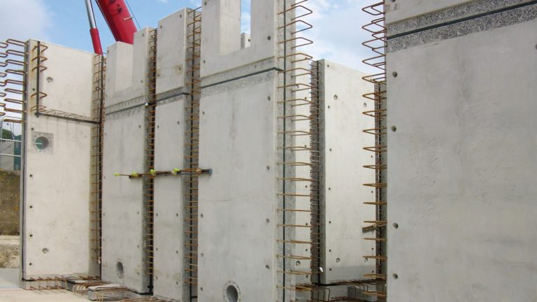
Precast concrete wall panels – Courtesy of MMB
In addition to the PCC solution for the tertiary plant, Design for Manufacture and Assembly (DfMA) was used to reduce on-site construction and installation times, reduce working at height and improve site health and safety. For example, access metalwork was assembled in sections off-site, ready to be delivered, craned and fixed into position.
The chemical storage, make-up and dosing plant was specified as factory fitted and tested self-contained pre-fabricated GRP kiosks, 4m x 4m x 12m long, for installation onto prepared concrete base slabs, ready to be connected and commissioned. The increased storm tank capacity was achieved by raising the outlet weir and perimeter walls of the existing tanks using a ‘hit-and-miss’ precast/in situ concrete solution, to minimise the need to enter the tanks and maintain their availability for storm storage during the construction periods.
A package water booster set was specified for the potable wash-water system at the new inlet works site.
Alternative materials were specified where this would improve buildability, health or safety; draw-pit chambers and manholes were constructed using lightweight plastic shells, with either granular or concrete backfill.
Throughout the design and construction process, lessons learnt and good practice were passed between the MMB project teams for East Tanfield and Pegswood. This included MMB’s construction team for Pegswood visiting the East Tanfield site to witness the PCC construction process, to the benefit of the follow-on project.
East Tanfield STW – Key participants: Designers, contractors and suppliers
- Client: Northumbrian Water Group
- Principal designer & main contractor: Mott MacDonald Bentley
- Precast concrete design & supply: Carlow Precast (now FLI Precast Solutions)
- In situ reinforced concrete & shuttering: North East Reinforcements
- Nitrifying submerged aerated filter (NSAF) & deep bed filter (DBF) process design & plant: De Nora Water Technologies UK Services Ltd
- Ground investigations: Dunelm Geotechnical & Environmental Ltd
- Foundation piling: Van Elle Ltd
- Automatic fine screens: Longwood Engineering
- Temporary works: Mabey Hire
- Grit detritor: Tuke & Bell Ltd
- Galvanised mild steel metalwork: JHT Fabrication Ltd
- Chemical dosing: Sheers
- Glass-coated steel sludge tanks: Goodwin Tanks Ltd
- Power supply transformer & kiosks: Gowland and Dawson Ltd
- Control panels: TES Group Ltd
- Control panel kiosks: Northern Pump Supplies
- PLCs & systems integration: IDEC Technical Services Ltd
- Electrical subcontractor: Intelect (UK) Ltd
- Submersible centrifugal pumps: Xylem Water Solutions
- Mobile cranes: Mammoet
Construction
Access into the site was at its upper end whereas the new tertiary plant was to be constructed at the lower end of the site, adjacent to the final tanks. The location was reached by an existing track down one side of the site. An early decision was to upgrade the track and extend it up the opposite side of the site to create a circular ‘one-way’ route for deliveries and construction plant, thereby removing the need for passing, reversing or turning large vehicles on site, so making for a safer site. NWG subsequently requested the circular access be retained for its own use after the project.
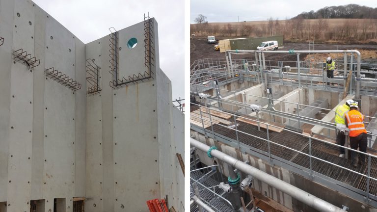
(left) Precast NSAF/DBF wall panels cast-in andd (right) mechanical install at DBF – Courtesy of MMB
The use of PCC for the tertiary plant allowed free-standing full-height wall units to be fabricated off-site, called-off and delivered in the order required for construction, on a ‘just-in-time’ basis to match the pre-determined installation sequence, working outwards from the furthest point, and avoiding site storage and double-handling.
A regulating layer of mass concrete was used to level out the sloping base of the redundant humus tanks at the design level. The footprint of each wall unit was marked on this surface for setting out purposes. The largest unit weighed 18 tonnes and at a reach of 40m required a 300-tonne crane. Precast concrete was also used for internal dividing weir walls, invert slabs and walls of elevated channels and chambers.
The wall units were installed in just two weeks, with the base slab and in situ wall joints completed within the following month. All PCC units came with starter bars, exposed aggregate and hydrophilic sealant strips already fitted, to remove the need for any on-site preparation at each 450mm wide in situ ‘stitch’ joint.
The in situ joints were made using 10mm aggregate concrete poured in full-height lifts. To reduce the need for temporary high-level access over the walls and into the tanks whilst installing internal components, special 1000mm wide ‘stitch’ joints, without projecting starter bars, were left unfinished to allow access into the tanks for construction workers until the internal work had been completed.
Again, to reduce working at height, flanged pipe inserts were cast into the relevant PCC wall units where required, to facilitate later high-level pipework installation. Similarly, high-level metalwork walkways and access platforms at the NSAF/DBF structure were constructed in manageable sections at ground level and craned into position.
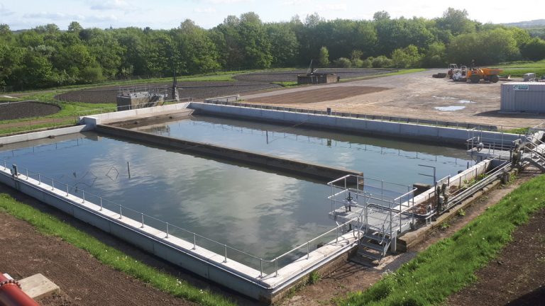
Storm tanks in operation, with raised outlet weir and peripheral walls – courtesy of MMB
Conclusions
Both East Tanfield and Pegswood projects were commissioned and operating within date for their new consents. The new NSAF/DBF plants are performing well, with very low ammonia levels being achieved at both sites, and low phosphorous at East Tanfield.