
Holloway Storm Relief Sewer (2021)
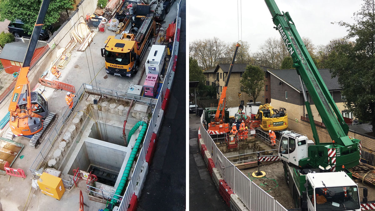
(left) Site view during benching activities and (right) Flap valve installation - Courtesy of J Murphy & Sons
In the 1850s, London’s population was approximately two million. In 1858, predicting population growth, Sir Joseph Bazalgette constructed a combined sewerage system collecting both wastewater from homes and businesses, and rainwater run-off, to serve a population equivalent of four million. Now, with London’s population approaching nine million, the sewerage network can become overloaded during severe storms and times of heavy rainfall, resulting in spillages into the Thames with the resultant ecological and aesthetic impacts. Thames Water sees such overflows as unacceptable and is accelerating work to eradicate them across its 68,000 mile sewer network.
Currently under construction, the 25km Thames Tideway Tunnel will intercept spills from 34 combined sewer overflows (CSO) and transfer wastewater to Beckton STW for processing. At the King Edward Memorial Park Foreshore site, the tunnel turns away from the River Thames along the Limehouse Cut towards Abbey Mills Pumping Station. As a consequence, the Holloway Storm Relief Sewer (HSRS) CSO, further east along the river, will not be connected directly to the Tideway Tunnel. An alternative solution for intercepting, storing and transferring wastewater away from the river at this location was therefore required.
Project summary
The Bekesbourne Street Project involves the modification of the existing sewerage network by intercepting flows from the Holloway Storm Relief Sewer (HSRS) and diverting them by way of a new weir chamber into the existing Northern Low Level Sewer No.1 (LLS1). This allows the Holloway Storm Relief Sewer (HSRS) to flow into the Low Level Sewer 1 (LLS1) during dry flow conditions.
However, and as per the current situation, during severe storm events when the system surcharges with flows from HSRS and LLS1, the new arrangement is designed to allow flows through the new weir chamber to overflow over the weir wall through a flap valve into the river. As this site is relatively independent of the main Thames Tideway construction work, these modifications were delivered as a standalone Thames Water infrastructure project by the Eight2O Alliance.
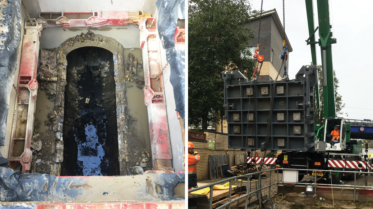
(left) Holloway Storm Relief Sewer post removal of the crown and (right) Weir chamber non-return valve being installed – Courtesy of J Murphy & Sons
The ECI phase
Following trial holes conducted in early 2014, Atkins (principal designer of the Eight2O Alliance) developed the design solution. In June 2017, J Murphy & Sons was appointed by Eight2O, under an ECI subcontract award, to review and develop the proposed design and ensure all constructability aspects were thoroughly critiqued and the construction risk was managed during design development. Upon successful completion of this initial input phase, Murphy were appointed as principal sub-contractor in December 2017 with the responsibility to deliver the solution.
At commencement of the ECI phase, the design for prevention of silt build-up due to static water within the HSRS was not finalised and two options for the regarding of the HSRS were under consideration. Option 1 was to lower the level of the cross-connection between the HSRS and the LLS1 with Option 2 to raise the level of the floor of the HSRS to match the floor levels in the cross-connection. Option 1 was initially favoured prior to ECI phase constructability analysis, however Murphy demonstrated that Option 2 was actually better suited. Atkins took this recommendation on board and proceeded to incorporate Option 2 into the final design.
Constructability analysis identified the real risk of inundation of water into the new weir chamber existed during construction due to the constraints when working in the HSRS. Through collaborative working between Murphy and Eight2O during the ECI phase, these risks were controlled and mitigated, allowing the project to proceed into the construction phase.
Risk from flows from upstream: As storm relief sewers are effectively the last line of defence against localised flooding, isolating or diverting the HSRS for long periods of time during construction was not considered a viable option. Sewer modelling and calculation of evacuation times was undertaken during the ECI phase which allowed the development and implementation of a live sewer monitoring system, with early warning alarm for operatives working in areas of potential risk. In conjunction with this ECI phase risk assessment model, Thames Water’s ‘ICM Live’ sewer activity forecasting program was used to predict suitable and safe working periods prior to operatives commencing work within the new weir chamber and the sewer.
Risk from flows from downstream: The location of the new weir chamber is 230m from the river CSO and the invert level of the weir chamber is 4m below high tide level. During the ECI Phase it was identified that the existing CSO flap valve was leaking and would require replacing prior to the construction of the new weir chamber. Thames Water replaced the leaking flap valve with a bespoke quadruple Tideflex valve arrangement. However, as this was a single isolation from the river, a second defence consisting of a live sewer monitoring system again combined with known evacuation times was developed to protect the operatives working within the new weir chamber and the sewer.
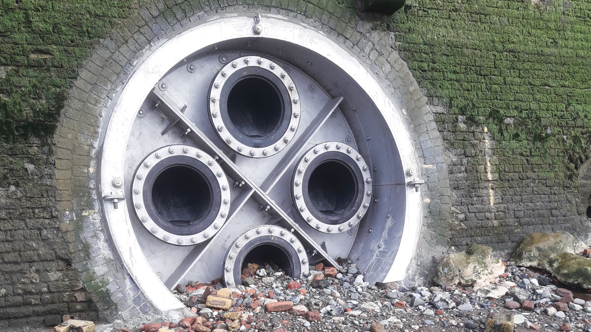
Tideflex valve installed by TWUL – Courtesy of J Murphy & Sons
Bekesbourne Street was chosen as the most suitable location for construction of the weir chamber as critically there is a cross-connection between the HSRS and the LLS1 under the intersection of Bekesbourne Street and Ratcliff Lane. However, a key constraint with working in Bekesbourne Street is access; both for the construction works and most importantly to maintain a safe thoroughfare for local residents. There is no alternative access and options for creating a new access road were ruled out early in the ECI.
It was not possible to obtain permit for complete road closure of Bekesbourne Street for the duration of the weir chamber construction works so an innovative site boundary alternating sequence was developed by Murphy to ensure continual safe access for local residents and pedestrians whilst maintaining the construction programme.
Additionally, the ECI phase identified and implemented efficiencies achievable within the routes for the enabling service diversions required to facilitate the weir chamber construction.
The construction phase
The following construction phase work elements are explained in detail below:
- Enabling works.
- Ground movement monitoring during permanent works.
- Weir chamber construction.
- HSRS regrading.
- EICA.
- Reinstatement.
Enabling works
Bekesbourne Street is a single lane entrance to a residential area lined with mature trees and parking bays at either side. The first step of the enabling works was the removal of all street furniture, parking bays and trees to open up enough space for the construction site and lane diversion to cohabit the space.
Following this, the diversion of UKPN LV, BT, Gas (125mm LP), TWUL water (125mm and 63mm) and a 300mm local sewer buried services was undertaken using Murphy’s in-house capabilities.
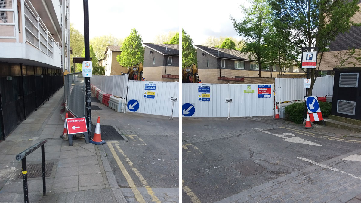
Street configuration during construction – Courtesy of J Murphy & Sons
Ground movement monitoring
The requirement for ground movement monitoring was identified during the ECI phase. The adjacent building foundations (John Scurr House) were located within the zone of influence of the shaft accommodating the new weir chamber and the nearby Lime House DLR Station contained escalators which could only tolerate settlement of 1mm.
A monitoring regime was set up and implemented by Murphy on the adjacent buildings and movements recorded against the baseline, analysing the data through a RAG spreadsheet with an accompanying escalation procedure.
Weir chamber construction
The weir chamber construction consisted of firstly excavating down over the HSRS. A temporary secant chamber was piled around the existing sewer. As the shaft was dug within the temporary secant chamber, supporting frames were installed with the design considerate of loadings from the adjacent buildings.
As space was restricted, the secant chamber was designed as the minimum diameter permissible and rather than back shuttering the permanent chamber walls, the temporary secant piles were spray-lined with concrete, float finished to 1-3mm accuracy and cast against.
Dry weather flows (DWF) were diverted into the LLS1 by means of dam boards and the crown of the HSRS was line sawed into sections and lifted out of the shaft. The new weir chamber was cast inside the temporary secant chamber forming the connection to the HSRS by means of bespoke drum shutters.
The 4.5te flap valve from Waterfront Fluid Controls was mounted on the dividing wall behind weir opening. Access ladders and platforms from Steelway were installed and a precast concrete cover finished-out the chamber. The chamber has sealed manholes and is vented via a newly installed vent column.
HSRS regrading
Following completion of the new weir chamber, to permanently divert dry weather flows (DWF) to the LLS1 via the cross connection, an existing flap valve had to be removed from the cross connection. The level difference between the cross connection and HSRS was approximately 400mm so to prevent a build-up of silt within the HSRS, a concrete bench 280m long ranging from 600mm deep to 50mm deep was cast.
The original methodology for delivering concrete into the live sewer, while contending with the DWF, was to utilise dry sprayed concrete and construct half the bench at a time while the DWF passed the work front on the opposite side. However, when it came to completing the benching, the DWF encountered resulted in water velocities in excess of that predicted and rendered the proposed methodology ineffective. It therefore became necessary to isolate the sewer during periods of low-flows to allow lining works to progress. Murphy developed a solution using a temporary cone stopper capable of rapid deflation combined with upstream network monitoring to safely complete the works and ensure no detrimental impact to sewer capacity.
Following Thames Water approval of the proposed sewer isolations, development of the benching method also allowed optimisation of the work methodology which resulted in casting of the benching in three pours rather than an estimated twenty-eight pours, with the dry sprayed concrete technique. While developing the benching methodologies, trials of spray concrete techniques and trials determining the viscosity of bespoke concrete mix designs were conducted to validate the proposed methodology.
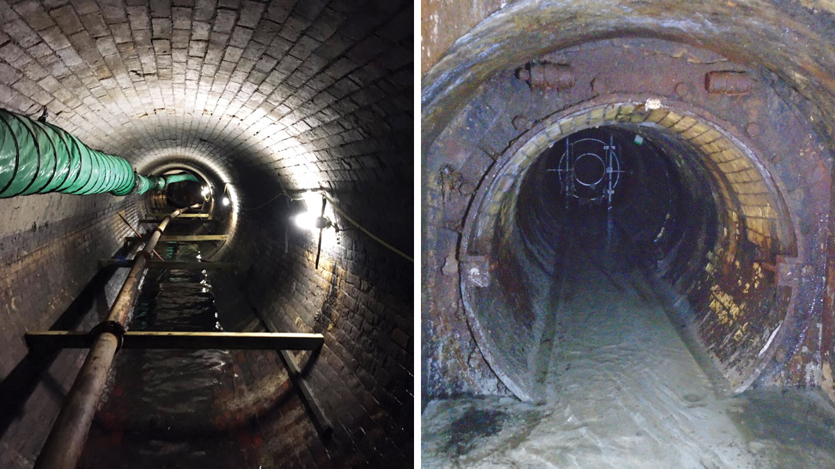
(left) Inside the Holloway Storm Relief Sewer with concrete pump lines, ventilation and lighting in place and (right) completed benching at the point where the HSRS meets the cross-connection – Courtesy of J Murphy & Son
Holloway Storm Relief Sewer (Bekesbourne Street): Supply chain – key participants
- Project delivery: Eight2O Alliance
- Designer: Atkins
- Main contractor: CABV JV
- Principal sub-contractor: J Murphy & Sons
- Temporary works: MGF Ltd
- Flap valve: Waterfront Fluid Controls
- Access ladders & platforms: Steelway
- Telemetry: JR Pridham Services
- Tideflex valve: Measurit Technologies
EICA scope
Civil works for the DNO/ADSL were completed by Murphy, while telemetry installation and commissioning was undertaken by Murphy’s supply chain partner, JR Pridham Services. The EICA elements consisted of the installation of:
- Upstream and downstream level monitoring of the HSRS within the new weir chamber.
- A kiosk at ground level complete with services and telemetry.
- Incoming single phase power supply from DNO.
- Incoming ADSL communications.
- Modifications to TWUL top end SCADA.
Summary
Delivery of the Bekesbourne Street Project posed complex challenges. These challenges predominantly related to ensuring unaffected service to Thames Water customers, the maintenance of safe access for local residents and the public and the safety of the Project construction team whilst working in a live sewer. Through effective collaboration between all members of the Project Team, the project was successfully commissioned and handed over to Thames Water in early 2021.
A positive legacy of how the project was delivered is the strong relationship fostered with local stakeholders such as the Bekesbourne Street residents, John Scurr Community Housing and The Royal Foundation of St Katharine over the three years Murphy worked in the area. This was achieved through regular communication, frequent drop-in sessions, community garden maintenance days and a children’s tea parties hosted in the grounds of John Scurr House.