
Howdon STYW – CHP (2020)
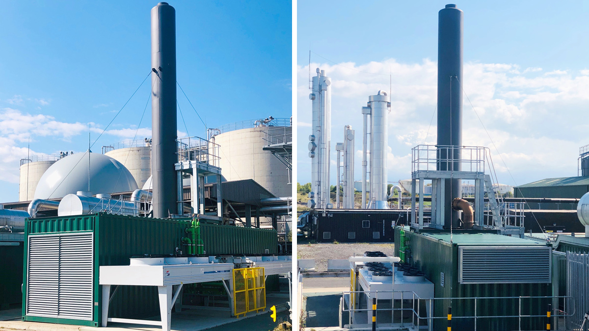
Howdon CHP completed works - Courtesy of NWL
The advanced anaerobic digestion (AAD) plant at Howdon STW includes 3 (No.) MWM gas engines that were commissioned in September 2013. The engines originally used biogas from the digestion process as fuel to produce steam for the thermal hydrolysis plant and generate electricity. The electricity generated by the engines when running on renewable biogas is eligible for payments under the Renewable Obligation Certificates (ROCs) scheme and the Climate Change Levy (CCL) tax exemption. The gas to grid (G2G) plant was installed at Howdon STW in 2014 enabling the biogas produced through the AAD process to be purified and mixed with propane and then exported to the gas distribution network. The injection of gas to grid is eligible for payments under the Renewable Heat Incentive (RHI), and because of greater efficiency of this process, a higher tariff is achieved compared to ROCs.
Background
The daily income associated with G2G is significant for Northumbrian Water (NWL). Imported propane gas is added to the purified biomethane to match the required calorific value targets set by Northern Gas Networks. As part of the G2G project, the gas engines were converted to be able to run on grid gas and for this to become the normal fuel source, as this mode of operation is more cost effective than buying grid electricity. However, the change of gas source at Howdon from the biogas to imported natural gas has had tax implications in the form of CCL exemption due to the CHP QA index.
NWL highlighted an issue where they were producing excess biogas from the AAD Plant. This excess biogas was being flared off due to limitations of the biomethane upgrade plant (BUP) and the export licence agreed with Northern Gas Networks.
Mott MacDonald Bentley (MMB) were commissioned to carry out a study to determine the available biogas levels and to propose a solution to utilise this resource more efficiently which would have the 2-fold benefit of reducing flaring and allowing Howdon to become energy self-sufficient.
Following the results of the feasibility study, NWL commissioned MMB to investigate the possibility of changing the operation mode of the existing CHP and G2G systems to enable more efficient resource management by way of installing a new natural gas-powered engine. This was developed and a new engine was installed in Summer 2019 and commissioned and brought into service December 2019.
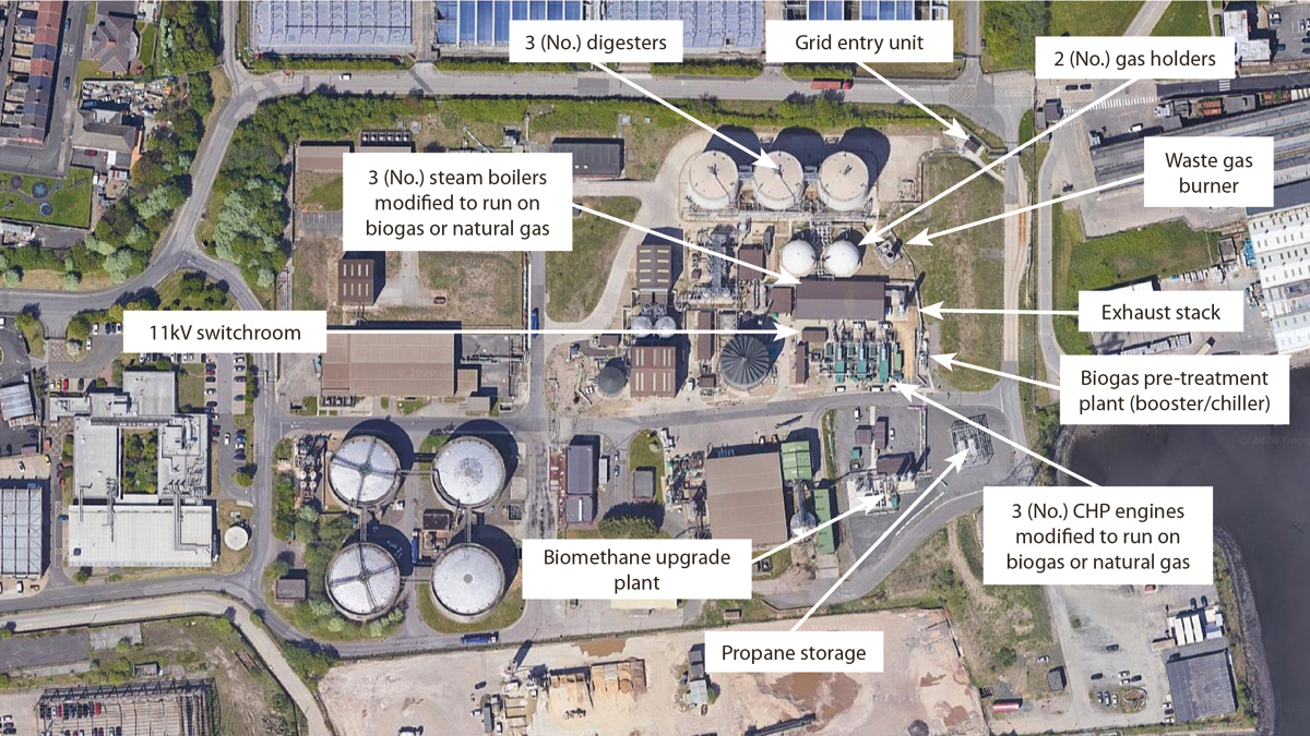
Overview of the Howdon AAD and CHP area (Google Maps) – Courtesy of MMB
Feasibility study
The scheme drivers were as follows:
- Biomethane upgrade plant (BUP) is not large enough to process increased biogas production.
- Seasonal low demand in gas network means Howdon grid entry unit (GEU) cannot always pass full natural gas production of BUP to grid.
- Resulting >10% use of waste flare with an increased risk of breaching environmental permit and lost energy revenue.
- Previous conversion of existing gas engines from biogas to normally run on natural gas has reduced CHPQA QI < 100 and therefore CCL costs are incurred.
From a review of SCADA outputs, the additional flow of biogas required to be passed to the CHP engines, in order to reduce the waste flare use to an acceptable level, is equivalent to the amount burned in burner 1 of the flare; i.e. 340 Nm3/h.
The options followed and discussed were:
- Option 1: Do not divert waste gas – Change operating system to only send to waste gas burner at maximum burning rate.
- Option 2: Divert waste gas to new engine.
- Option 3: Divert waste gas to existing or new boiler.
- Option 4: Divert waste gas to existing biomethane upgrade plant.
- Option 5: Divert waste gas to new biomethane upgrade plant.
- Option 6: Blend waste gas into existing engines.
- Option 7: Blend waste gas into existing boilers.
- Option 8: Install a new 1.75MWe engine running purely on natural gas, and switch over one of the existing engines to 100% biogas.
The original terms of reference for the feasibility study were to develop Option 2, but the economics proved unfavorable. Option 8 was introduced as an alternative method to eliminate flaring and reduce the reliance on imported electricity. Additional heat extraction was determined to be not required as the existing CHP engines feed the separate boilers, and the heat load is met.
The new engine proposed was to be fueled by natural gas only and installed without the capability to extract the waste heat. CHP1 engine will be switched over to 100% biogas and the throughput of the CAMBI Process set to maximise available biogas flow.
Proposed plant location – Courtesy of MMB
MMB defined the plant, equipment and tie ins to attach the proposed new engine to the existing gas, water, HV and LV systems, and an economic analysis was carried out to determine the feasibility of the project, taking into account the inputs of fuel, water, chemicals, OPEX, CAPEX against income from RHIs, ROCs and reduction in plant running costs.
By setting aside one of the existing engines purely to biogas, this will use up the 400Nm3/h of waste gas currently burned in the waste gas burner, combined with the additional biogas generated by the CAMBI process. This will reduce burner operating frequency to emergency use only, a level whereby the risk of prosecution is minimised.
In addition, a large proportion of the plant steam demand is met from the biogas engine (CHP1) which will increase the CHP QA to a reasonable level, meaning that a reduction in CCL could be realised. The economic analysis identifies that running the AAD at 105 tDS/d (Option 2) gives a significant return (£551k/yr), and if the AAD throughput can be increased to 110 tDS/d (Option 3) this rises to £645k/yr. In practice, the figure is likely to be somewhere in between due to variations in plant availability.
The proposed new 2MWe gas engine would be powered by imported natural gas which will reduce the plant’s imported electricity. Given the payback rates determined in the economic analysis, this would give a payback period of 4.2 years.
The notional solution agreed was for one of the existing engines to be set aside purely to biogas, using a proportion of waste gas currently burned in the waste gas burner. The new gas engine was originally to be sized at 1.75MWe and be powered by imported natural gas, however after liaising with engine suppliers it became apparent the closest possible option available on the market that would meet the requirements of the scope was a 2MWe natural gas engine this option was therefore taken forward.
To supply the new engine with natural gas, the existing DN150 SS natural gas pipework would need to be modified. A new DN100 SS branch ties into the existing pipework and terminates by tying into engine supplier gas line inlet.
The existing 11kV switchboard would need to be extended and a new 11kV switch installed on the switchboard.
Investigate and define (I&D)
- The generator could be sized to supply at 400V, therefore a 2000kVA step-up transformer was required. The transformer was to be positioned in line with existing transformers for Engines 1, 2 and 3.
- Alternatively, the generator could be sized to supply at 11kV, in which case the step-up transformer would not be required.
It was decided that the preferred solution to install the 11kv HV option of the 2MWe gas engine was deemed more efficient considering cost benefits with no requirement for an additional step up transformer on site or related civil works such as transformer slab, ducting etc.
Various suppliers were approached to carry out the works including:
- Engine sub-contract package: Cooper Ostlund (MTU gas engine/generator, packaged and containerised by ETW
- Pipework modifications: Dustacco Engineering
- Systems integration: IDEC
- Panel modifications and LV cabling: Intelect
- HV cabling: IUS
The investigation phase highlighted issues such as buried services in the area, poor ground conditions, other redundant equipment, and oil tanks and storage units in the area, which would need to be relocated or removed.
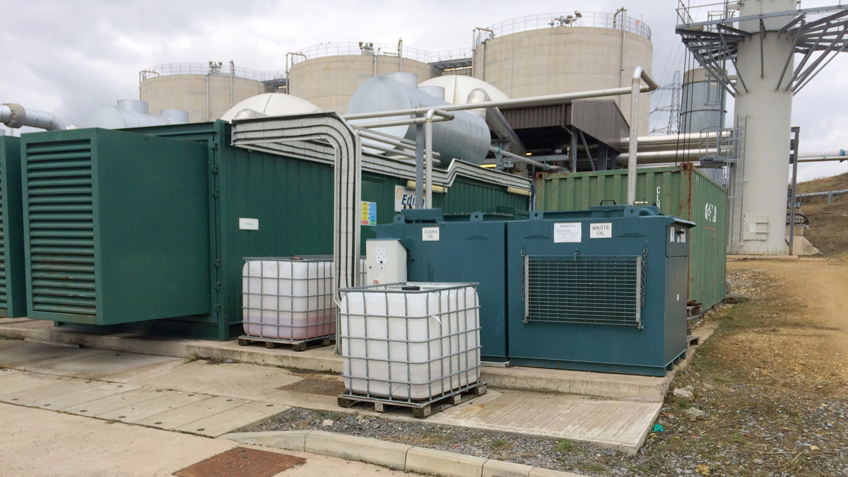
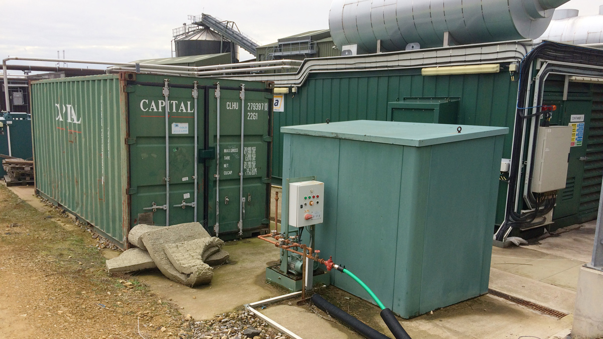
Obstructions in the proposed location – Courtesy of MMB
The exhaust stack height for the proposed engine was determined by way of dispersion modelling carried out by the internal Mott MacDonald air quality team.
The dispersion modelling method model’s movement of air over and around surrounding buildings and generates areas of flow circulation, which can lead to increased ground level concentrations in the building wakes. The model area was undertaken across a Cartesian grid with 50m receptor spacing up to 2km radius around the emission source to identify maximum concentrations for all areas, including the nearest residential areas and to produce contour plots.
A stack height of 13m was shown to ensure that the locations outside of the wastewater treatment works or industrial areas, where sensitive members of the public are likely to be present, are expected to have much lower NO2 concentrations than the air quality objectives. Therefore, no significant air quality impact was anticipated.
The Definition Phase developed these quotations for sub-contracts and the civils works for access and foundations for the equipment, requiring a 2.8m x 14.8m extension of the existing slab (300mm thick with a layer of A393 mesh to the top and bottom). This would reduce the existing vehicle track to the east of gas engine CHP3 to a 2m wide pedestrian footpath.
Vehicle access to the flare stack would therefore only be possible by an out-and-back route via the existing 3m wide access road to the north of existing CHP transformers. A hardcore hammerhead turning point was designed on the existing slab area to the immediate west of CHP1, 2 and 3 combined exhaust stack (existing shed within the area to be relocated). A hammerhead turning point was sized for vehicles no larger than a transit van (or equivalent) to allow access to the flare stack for routine operations, sampling and maintenance.
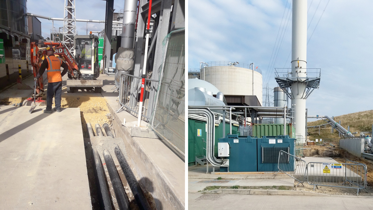
(left) Installation of new ducting for HV cables from the engine to the substation and (right) completed construction of the slab – Courtesy of MMB
Design and construct (D&C)
Following agreement of a target cost in the I&D stage, NWL commissioned MMB to deliver the defined solution through a D&C contract under Option C of the NEC Contract. This commenced in November 2019 with a collaborative launch to engage all key stakeholders and the design team who were based on site from day one.
Orders were placed immediately on the commencement of the D&C contract for the engine supplier, with additional contracts placed over the next 3 months. Construction works started in March 2019 to tie in with the programmed engine delivery at end of June 2019. Commissioning and testing were programmed throughout July.
Initially there were several challenges:
- The original design required for the oil tanks for the existing engines to be rotated but once the actual dimensions of the new engine container were known it was clear that they were in the way of the required slab for the new engine. These were required to be moved to the west side of the CHP area and the pipework re-routed.
- Additional requirements from the Environment Agency dictated permanent access to the emissions monitoring ports on the exhaust stack, leading to the design and installation of an access platform.
- Poor ground conditions and volume of buried services required the novel design of equipment foundations to bridge over problem areas.
- During the D&C phase the European Directive for power generation EREC G59 was to be replaced with G98/G99, this would come in to force before the equipment was to be brought online.
- The systems integration of the new engine into the power management for the entire site was a complex task carried out by IDEC.
The construction side went well and was completed in advance of the programme, once the oil tanks were moved.
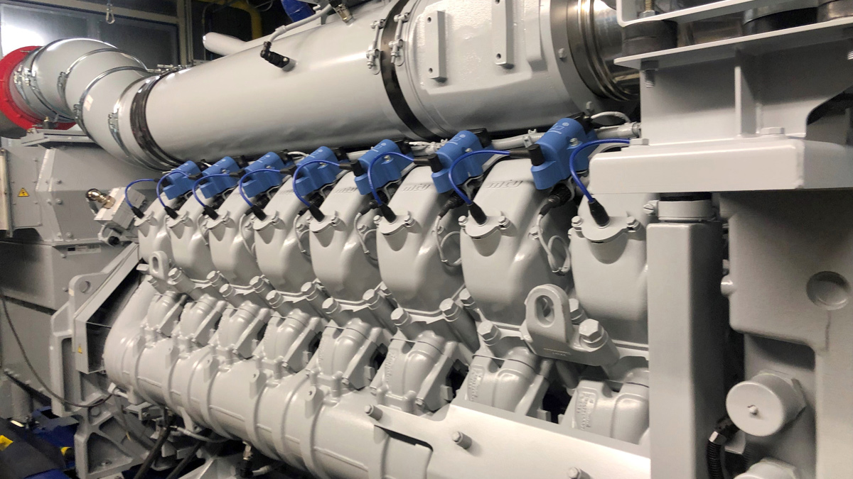
Engine on test in MTU works – Courtesy of MMB
The engine was delivered and installed in June/July 2019, ready for commissioning. The issues surrounding G99 became more apparent once the distributed network operator (Northern PowerGrid), MMB, NWL and the generator supplier understood the full scope of testing required to satisfy the new requirements. This included the frequency ride through and response characteristics to ensure that the generator did not adversely affect the grid in the event of a trip or out of range operation. This required a full type test of a similar engine at the suppliers works and extensive on-site software modifications which were demonstrated to the distributed network operator before acceptance was granted.
The testing was witnessed by the distributed network operator in December 2019 and the equipment was successfully handed over to NWL in March 2020.
Howdon CHP – designers, contractors and suppliers – key participants
- Client: Northumbrian Water Limited
- Principal designer and main contractor: Mott MacDonald Bentley (MMB)
- Package of unit into container and auxiliary equipment: ETW
- Supply of engine/generator unit: MTU
- MTU engine package sub-contractor: Cooper Ostlund
- Stainless steel pipework and fabrications: Dustacco
- Systems integration: IDEC
- Electrical sub-contractor: Intelect
- Electrical sub-contractor: IUS
- HV Switchgear: Schnieder Electric
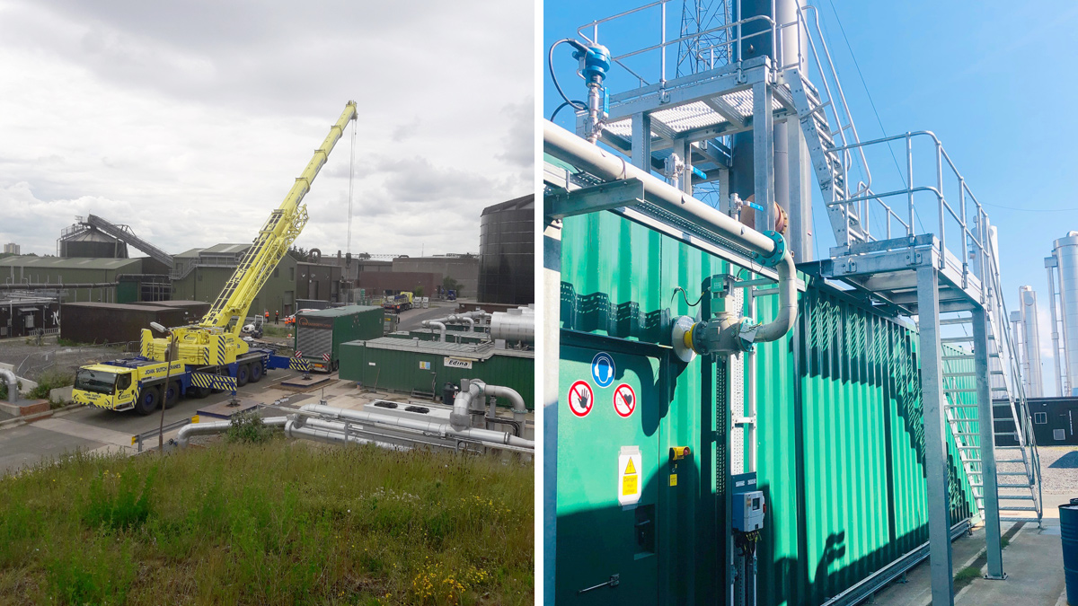
(left) Taking delivery of the engine container – Courtesy of MMB, and (right) access platform to the exhaust – Courtesy of NWL
Conclusions
This MMB project successfully delivered a power generation solution to NWL to allow them to improve the flexibility of their operating methodology on site. The on-site electricity demand of 6MWe is now met by the 3 (No.) dual-fuelled Edina/MWM engines, and the new 2MW Cooper Ostlund supplier MTU engine. The heat demand for the CAMBI process is met by the existing CHP engines. A number of challenges were met and overcome by the collaborative project team consisting of consultants, suppliers, sub-contractors, the customer and the end-user.
By switching over one of the existing engines to biogas, NWL’s Howdon site is able to continue to sell biomethane to the Northern Gas grid and use any excess to modulate the proportion used for fuel to meet grid demand and to reduce flaring duration to emergency purposes only.