
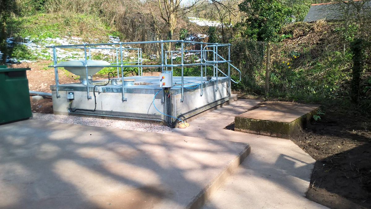
Kiln Road Sewage Pumping Station (2019)
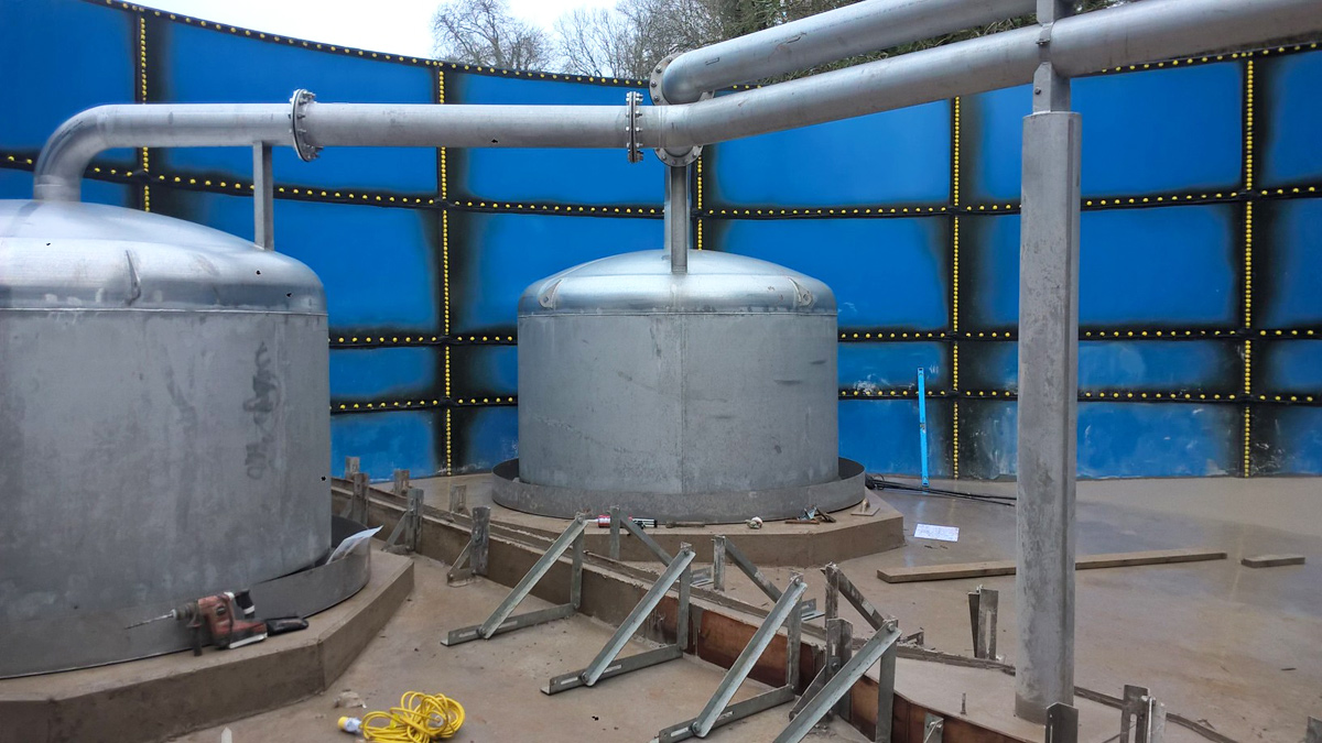
Storage tank (under construction) complete with flushing bells - Courtesy of Arcadis
The 2010 Shellfish Waters Directive placed a new obligation on South West Water (SWW) to ‘endeavour to meet’ the Shellfish Waters Regulations ‘Guideline’ Standard (Class B). The Shellfish Waters (SFW) programme of work was to meet legislative requirements to protect or improve designated shellfish waters to support shellfish life and growth, contributing to the quality of shellfish products produced in commercial shell fisheries. The investment has helped SWW to deliver its commitment for reducing pollution incidents and in doing so support the regional community and economy.
Background
At PR14 (2014 price review) the National Environmental Programme (NEP) identified a Phase 1 programme valued at £120m. This was agreed to be unaffordable for the business and there would be a non-cost beneficial customer willingness to pay. Further investigations and discussions with the Environment Agency (EA) reduced the programme in phases from the initial £120m to an acceptable agreed Phase 5 value of £26m.
The Phase 5 programme identified high priority catchments in the region which involved storm discharge improvements at 28 locations across eight estuary catchments.
Development
The initial objective was based on a maximum of 10 spills per year (agglomerated) >50m3 or improved discharge quality. By challenging the original outputs through modelling and combined sewer overflows (CSO) impact assessments, three of the sites have proved to be compliant and therefore removed from the list. The modelling review also identified significant reductions in scope at many sites, specifically where storm storage solutions were originally proposed.
Wherever possible sustainable solutions have been developed using the principles in the Design Hierarchy as detailed above.
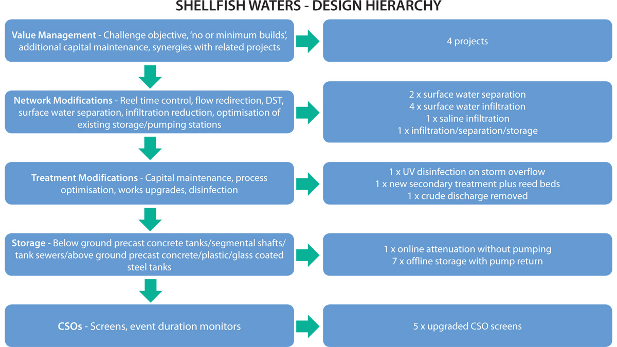
Shellfish Waters Design Hierarchy
Project delivery
The above scope of works included 2 projects which involved removal of surface water infiltration, both of which had funding for second phases depending on how successful the first phases were in reducing infiltration. Both phase 1 projects were successful negating the need for further work.
The work was cost effectively delivered through the H5O Delivery Alliance with 11 projects being delivered through the Tier 1 partner contractors and 13 through the Tier 2 contractors. The works were delivered as a package under the Alliances SIPi arrangements, the overall package with H5O was £18,980k with projects ranging from £70k to £3,650k.
Kiln Road Sewage Pumping Station (SPS)
This project was required to reduce the number of significant storm spills to the environment from Kiln Road SPS combined sewer overflow (CSO). A new storm storage tank, located in brownfield land adjacent to the existing SPS compound (this land was purchased by SWW as part of the scheme), will reduce the number of storm spills by providing a minimum of 450m3 storage. The stored volume will be filled via a new dedicated SPS and returned by gravity at a rate of approximately 10 l/s via an actuated control valve to the existing CSO structure upstream of the existing SPS, after storm flows recede.
Works included:
- Modifications to the existing CSO chamber including new screen, odour control, access covers and measure to improve the safety systems of work.
- Diversion of the existing storm overflow sewer into a new Tank Fill SPS.
- Construction of a 2.7m diameter x 3.5m deep tank fill SPS, associated rising mains and overflow sewer.
- Construction of a 13.3m diameter x 6.5m high 450m3 circular bolted sectional steel storm storage tank with flushing bells; reasonings for this can be seen in the ‘Additional Design & Construction Challenges’ section.
- Piling to enable the above tank to be competently founded.
- Construction of a gravity sewer to return flows to a location upstream of the existing CSO.
- Construction of an overflow pipe from the storm tank to the existing CSO.
- Construction of an air vent pipe from the storm tank to the existing CSO.
- Associated pipework, control valve chamber, flow meters, control cabinet and cable ducts.
Environment Agency permit
Due to the changes to the control philosophy of the SPS a new Environmental Permit was required from the EA which required a ‘no detriment’ solution compared to the original philosophy. Figure 1 (below) shows the final operating techniques for the SPS.
Operation at Kiln Road SPS CSO
- Under normal operation flow passes through the CSO to Kiln Road SPS.
- If flow exceeds the pump rate at Kiln Road SPS, the level in the CSO chamber will increase and flow through the MecMex mechanical screen from Eliquo Hydrok Ltd, unless flows are beyond the capacity of the screen, in which case they will pass over the screen’s overflow weir. Storm flow (screened or unscreened) will discharge into the tank fill SPS wet well.
- Sewage is pumped from the tank fill SPS to the storm tank.
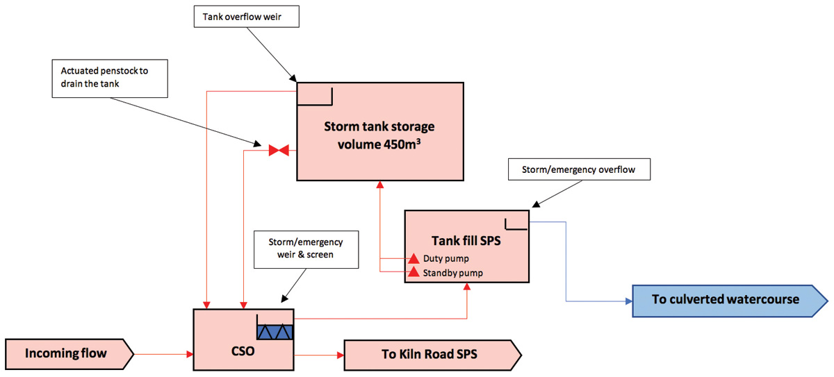
Figure 1
- If the tank is not full before the end of the storm, the penstock will open and allow the tank to drain when there is sufficient capacity at Kiln Road SPS.
- If the tank fills before the end of the storm, the pumps at the tank fill SPS will switch off allowing the level to rise in the tank fill SPS wet well before flowing over the storm/emergency overflow and on to the culverted watercourse.
- If the tank fills before the end of the storm and the pumps at the new tank fill SPS fail to switch off, then the level in the tank will rise to the tank overflow weir passing flow back to the CSO chamber and in turn to the tank fill SPS and then the culverted watercourse.
Flood risk assessment
The flood risk assessment was submitted as part of the overall environmental permit application for flood risk activities relating to this site. The EA raised a query regarding the proposed raised ground levels and construction of the storm tank above ground. The EA required further investigations into the effect of the proposed ground levels and tank on overland flow routes and floodwaters from the watercourse. The Galmpton Stream (the watercourse) is culverted under the site, extending approximately 110m upstream and 300m downstream. The EA raised concern about the potential impact the works may have on the extent and depth of overland flow through the site, which could potentially increase upstream flood risk to residential properties upstream.
Design alterations
The extent of the proposed footing/raising of ground levels surrounding the tank was reduced to improve overland flow conveyance.
Overland flow assessment methodology
The InfoWorks Integrated Catchment Modelling (ICM) software suite was used to predict the hydraulic behaviour of overland flow across the site under two scenarios:
- Current conditions.
- The proposed design.
Flow rate
A conservative overland flow rate of 1.6m3/s was used for this assessment which is the total 1:100-year return period (1% AEP) event flow rate for the watercourse, as stated in a document supplied by the EA (Galmpton Flood Defence Scheme – Operation & Maintenance Scheme). This was a conservative estimate because all the catchment flow was assumed to be on the surface rather than in the three culverts recorded in the area, which have an estimated combined capacity in excess of 1.6m3/s.
This estimate of culvert capacity was based upon culvert pipe sizes indicated by records and an assumed gradient using LiDAR data.
Model build
A triangulated irregular network (TIN) ground model was created in InfoWorks ICM using topographical survey data with the major existing structures on the SPS site explicitly represented. The topographical survey data was supplemented with 1m resolution LiDAR data to enable the model to extend a suitable distance upstream and downstream of the site. Existing upstream restrictions were not explicitly represented to provide a conservative assessment.
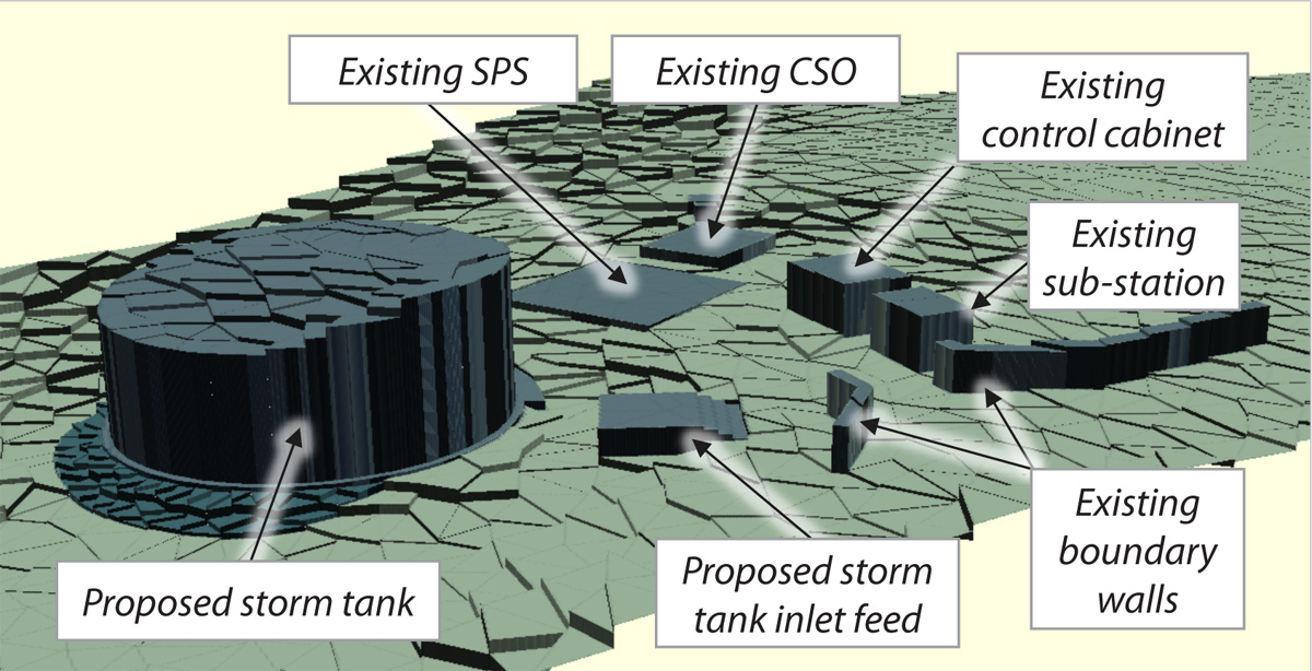
Figure 2: Extract from the surface model – Proposed – Courtesy of Arcadis
The model of the existing layout was then updated to represent the proposals. Figure 2 (above) is an extract from this model which illustrates the surface and structures included.
The inflow was introduced to the model along a 2D linear input source that spans the approximate width of the flood zone shown on the online EA fluvial flood map.
Results
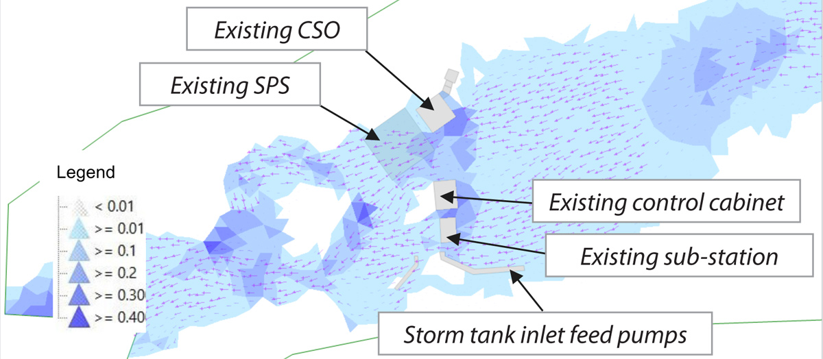
Figure 3: Predicted 1 in 100-year return period (1% AEP) event overland flow – Original – Courtesy of Arcadis
Figure 3 (above) shows the predicted flow through the existing site. The existing structures associated with the SPS had some effect on overland flows before they pass to the lower part of the site (where the tank is proposed). Some flow was expected to pass into Kiln Road but then divert back into the ‘valley’ shortly afterwards. A split in the flow was expected in the lower site due to a localised high point in the existing ground level.
Figure 4 (below) shows the predicted flow through the proposed site layout. The predictions showed a localised increase in depth around the new tank, the storm tank inlet feed SPS and the existing CSO (due to the access steps) but the overall effect on the SPS compound was considered insignificant. Flood risk in the land upstream of the existing SPS site was shown to be unaffected.
The results indicated minor adjustments to flow pathways through the existing SPS site due to the new access steps to the existing raised CSO structure. The predictions showed that overland flow can pass around the storm tank and inlet feed SPS in the lower part of the site.
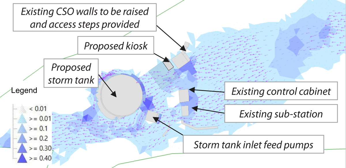
Figure 4: Predicted 1 in 100-year return period (1% AEP) event overland flow – New – Courtesy of Arcadis
Additional design & construction challenges
As the site is in a discussed quarry, hard rock was at a relatively shallow depth level which made a gravity fed tank inefficient due to the programme restrictions to meet the compliance deadline.
As such, an above ground, covered and pump fed storage tank was adopted for which the footprint was maximised so that the soffit of the roof would not obstruct the views and light of nearby properties.
To minimise the risk of odour and debris, flushing bells were installed, which are gravity operated via the breaking of a syphon pipe when the tank empties.
The CSO also needed modifications due to an increase in top water level due to additional flows from the storm tank return pipework. This involved working in the chamber whilst flows were live and, given the tidal nature of the catchment, hydrogen sulphide (H2S) was also a risk.
Completed CSO chamber with ventilation and protective handrailing – Courtesy of Arcadis
Scheme summary
The scheme was constructed and commissioned by the compliance deadline. Collaborative project team working, together with construction and detailed design efficiencies, meant the final project cost was £970k, resulting in a saving of £242k on the original Client Target Cost. Based on hydraulic modelling, the new scheme does not have a detrimental effect on up-stream flood risk.