
Kirk Hallam, Abbott Road, Flood Alleviation Scheme (2020)
Kirk Hallam Flood Alleviation Scheme - Courtesy of nmcn PLC (now Galliford Try)
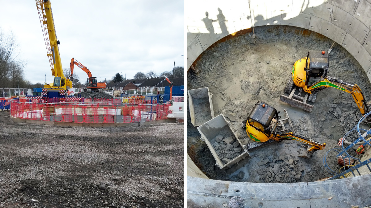
Kirk Hallam is a village on the outskirts of Ilkeston, Derbyshire in the East Midlands. It had a history of internal and external property flooding from the sewerage network in three separate locations within the catchment. Severn Trent (ST) appointed nmcn PLC (now Galliford Try) as the design and build contractor under the AMP6 framework to work collaboratively with the ST solution team to develop a sustainable solution to resolve the flooding issues. The solution was to upsize existing sewers, lay new sewers to convey flows away from affected areas, and provide an offline shaft (516m3) to temporarily hold flows until the downstream system had capacity for the flows to be pumped back into the system.
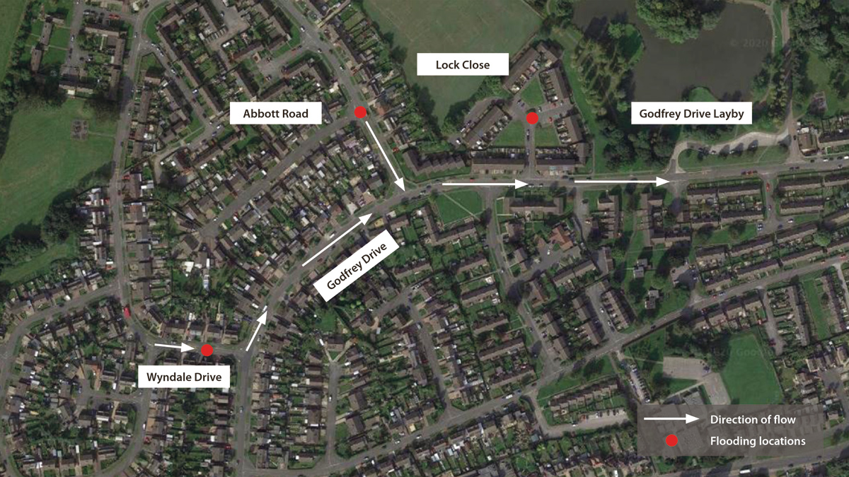
(Google Maps) Kirk Hallam catchment – Courtesy of nmcn PLC
Problem definition
Analysis of the ST hydraulic model and the ST flooding register identified that flooding occurred at three separate locations within the catchment. This was subsequently confirmed by onsite investigation and resident communications.
- Abbott Road: The area had seen much development in recent years and it was served by a single 150mm foul/combined water sewer (FWS). A Severn Trent capital scheme in 2002 abandoned a combined sewer overflow (CSO) 400m downstream of Abbott Road and no additional storage or conveyance was provided to compensate for the loss of the CSO. During storm conditions flooding was caused by hydraulic incapacity in the system.
- Lock Close: Flooding from the FWS was caused by hydraulic incapacity in the downstream system. In addition, the local topography conveys highway runoff into Lock Close at a low spot in the catchment area. The existing highway drainage that is connected into the surface water system did not have enough capacity to deal with additional runoff resulting in flooding to five properties.
- Wyndale Drive: Flooding was caused by hydraulic incapacity in the private sewer network and in the public FWS resulting in external flooding to two properties.
Development of complex engineering solution
The notional solution developed by ST was to upsize parts of the existing foul/combined and surface water systems to convey flows away from the affected areas. It also proposed to install an additional 516m3 of offline storage to provide flooding protection to properties for storm events up to 1 in 40 year (internal) and 1 in 20 year (external). The offline storage is required to temporarily hold flows within the catchment to not overload the downstream Ladywood Road Sewage Pumping Station (SPS). During the feasibility stage ST looked at separating the foul/combined systems however this was deemed too disruptive to customers as the majority of surface water connections to the foul were to the rear of properties.
Gravity sewer design & construction: To increase the capacity within the gravity sewer network an extensive programme of laying new and upsizing existing combined and surface water sewers (SWS) was undertaken in Abbott Road, Lock Close, Godfrey Drive and Wyndale Drive. The majority of this work was within the highway which was heavily congested with third party services. During the design phase a ground penetrating radar (GPR) survey was undertaken followed by a programme of targeted trial holes to identify potential clashes and steer the final design levels.
Due to the depth of the new sewer network and the number of existing services the sewers were constructed using a traditional open trench method. The trial holes in the highway established that the ground would be largely self-supporting and therefore trench and manhole temporary boxes were utilised during the pipe laying process to reduce installation times.
Off-line storage considerations: The first complex design consideration was to identify a suitable location in the middle of the housing estate to install the required storage volume. The nature of the roads and services in the area meant that on or offline pipe storage was not viable, so an off-highway area had to be found to site the new storage. Firstly, the location had to work hydraulically and provide the required storm protection levels. Secondly, the location had to be suitable for safe construction and future maintenance with minimal impact on the local community during and after the construction phase.
Downstream of all the flooding points a potential location for an off-line shaft tank was identified in a layby area off Godfrey Drive. Site investigations (SI), trial holes and a GPR survey confirmed the area to be free of third-party services. Borehole results confirmed that the ground was predominantly made up of weak sandstone with a layer of silty clay to a depth of 4m. The groundwater levels were also measured to allow for suitable dewatering the during excavation works.
The ST hydraulic model confirmed that a 10.5m diameter x 8m deep offline shaft tank at this location would provide the required protection to flooding properties.
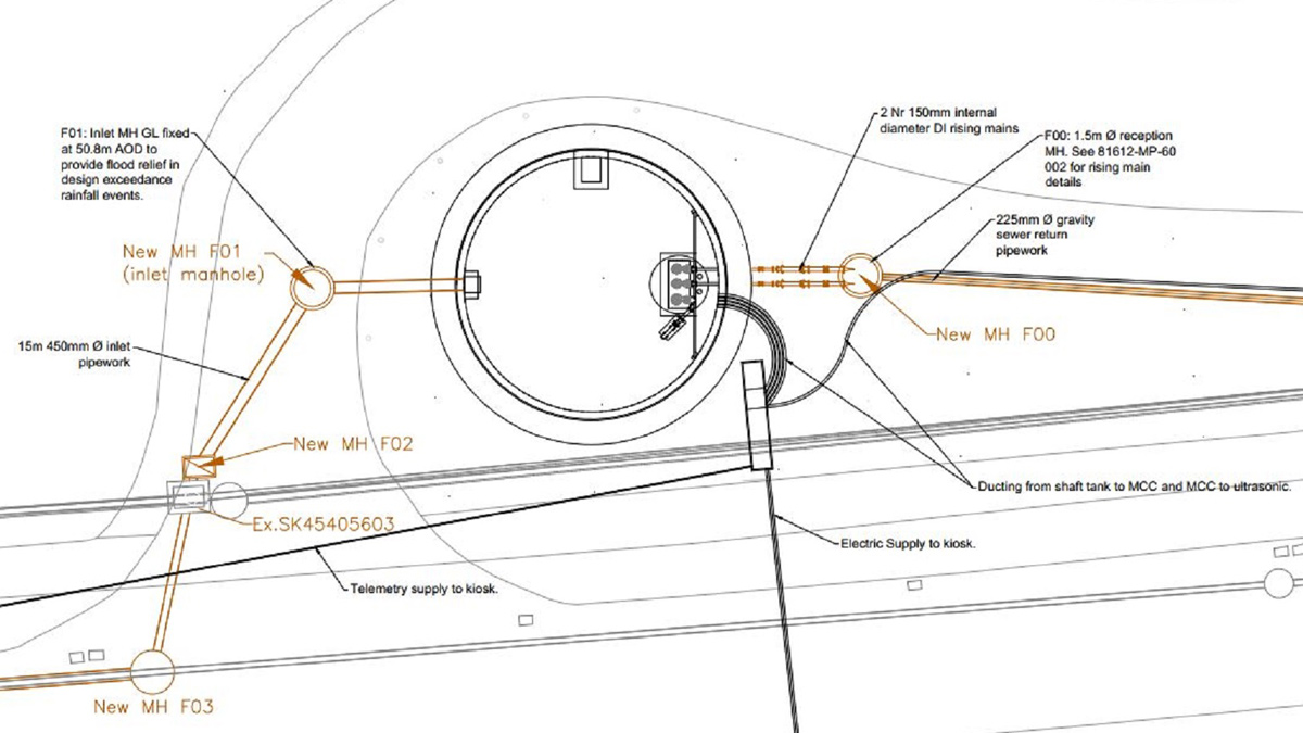
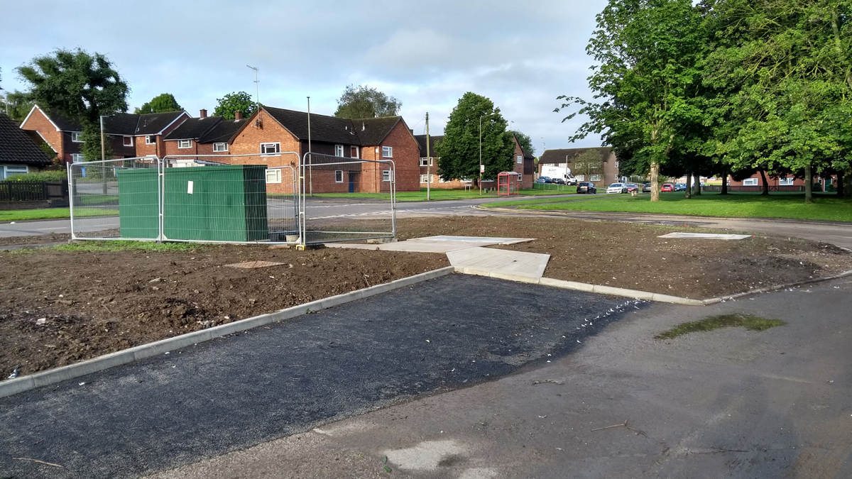
Shaft tank location – Courtesy of nmcn PLC
Innovation and sustainability
Shaft tank design: Sustainability was a key driver throughout the design phase. The design team was encouraged to look for innovations from the ST shaft tank design standard to enable the design and size of the offline shaft tank to be as efficient as possible. Reducing the overall construction dimensions had an impact on the quantity of imported material and volume of waste material being sent to landfill. Both, ultimately improving the carbon footprint of the scheme.
The SI results confirmed that the ground conditions would be capable of being self-supporting and would favour a shaft construction method known as under-pinning. As part of nmcn commitment to off-site manufacturing the shaft segmental rings, beams and cover slabs were all pre-fabricated off-site and brought to site as required. The location of the shaft tank in the layby area was perfect for the safe delivery and storage of materials.
A 1m x 1.6m deep concrete reinforced collar was designed to provide adequate support for hanging the segmental rings. This was cast around the circumference of the shaft excavation.
The ST shaft tank design standard shows reinforced concrete beams bearing on the concrete collar with the cover slabs bearing on the beams. Due to the proximity of the shaft tank to the highway the beams and cover slab where designed for accidental HGV wheel loading and were a substantial size. To achieve the standard detail the excavation would need to be 3m deep which would require significant temporary works to cast the collar in situ. To reduce the size of excavation an innovative design was put forward to ST and approved to recess the beams into pockets created in the collar. This reduced the depth of construction required for the collar installation and maximised the storage volume within the tank.
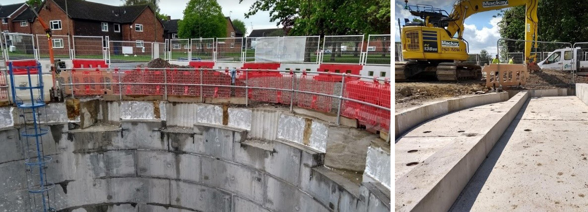
(left) Pockets cut into the collar and top ring segment and (right) beam and cover slabs in place – Courtesy of nmcn PLC
The ST hydraulic model was used to set the spill level from the existing gravity network into the off-line shaft tank. The level was set to utilise as much storage in the upstream gravity system as possible and therefore reducing the overall depth of the shaft tank construction.
The pocket recess design has been considered a success and as such the design detail has been used in other nmcn and Severn Trent shaft tank schemes.
Mechanical and electrical design interaction: An integral part of the design was selecting the most efficient pumping regime to empty the shaft tank quickly without causing detrimental flooding to the catchment as it empties. Two ultrasonic transducers were installed, one in the shaft tank and one in the receiving chamber downstream of the shaft tank. Following on from a period of heavy rainfall and when the shaft tank is in operation, once the flow levels in the main downstream sewer have sufficiently dropped the transducer in the chamber signals the pumps in the shaft tank to pump flows back into the sewer.
The M&E design team worked closely with the ST hydraulic modeller to get the on/off levels precisely calibrated so that the pumps did not inadvertently cause surcharging and flooding within the existing system. Getting this setting right also contributed to the efficient sizing of the shaft tank.
The project team’s commitment to efficient design reduced the depth of the shaft tank from the feasibility design by 2m, reducing the concrete required by 13 tonnes and the amount of muck away to landfill by 120m3.
Gravity sewer design: In total 20 new manholes were constructed within the highway. To reduce the construction programme, wide walled precast manhole rings were specified. Wide-walled manholes have a tongue and groove built into the wall to accommodate a bituminous sealant between the rings providing a watertight chamber and eliminating the need for a concrete surround. The use of this product reduces the installation time for each manhole, therefore reducing the construction programme and minimising the impact to the local community. This also reduces the materials (concrete) use on site and ultimately less waste being sent to landfill. This also reduced the carbon footprint of the scheme by minimising production and transportation of concrete to site.
Kirk Hallam Flood Alleviation Scheme – Key participants
- Design & build: nmcn PLC
- Structural design: Eastwood & Partners
- Open-cut gravity sewers: nmcn PLC
- Shaft installation: AMC Tunnelling
- MCC kiosk: Total Automation & Power
- Submersible pumps: Grundfos
- Lifting equipment: T Allen Engineering Services Ltd
- Pipes: Keyline
- Polysewer pipes: Polypipe
- Precast manhole rings: Marshalls CPM
- Shaft segments: FP McCann
Future maintenance
nmcn are committed to using digital technologies to deliver construction schemes. A BIM model of the shaft tank was built during the design phase to enable the ST operations team to visualise the site set up and flag any issues with future operational and maintenance regimes. One issue that was raised was manual handling of the pumps for maintenance and replacement. To reduce this risk davit arm sockets where installed to lift the pumps and a new footpath and maintenance layby area was constructed to allow access.
Shaft tank maintenance layby – Courtesy of nmcn PLC
Project and resource management
Throughout the duration of the project, collaborative planning was implemented in order to identify and realise efficiencies in the project programme. By being ‘high touch, low tech’, CP creates a ‘blue sky thinking’ programme by utilising easily moved post-it notes for multiple activities each day. One of the key benefits is it allows the site labour to be fully engaged in the planning process which draws on their hands-on experience as well as creating a sense of ownership across the wider team. Collaborative planning meetings where held throughout the design phase and the construction phase with key-representatives from the supply chain in attendance.
This was invaluable during the design stage to understand timescales and product procurement lead times and when submitting 3-month advanced notices for road closures and land entry.
During the construction phase a 2-week collaborative plan and a daily collaborative plan were utilised to maximise programme and delivery schedule efficiencies due to the limited space available to store materials on site. It was also used to challenge construction sequencing to drive programme efficiencies.
The whole delivery team were motivated and committed to deliver the scheme as efficiently as possible to minimise the disruption to the local residents.
Kirk Hallam Flood Alleviation Scheme – Key figures
- 10.5m diameter shaft tank construction to provide 516m3 of offline storage.
- 214m of new 300mm gravity foul sewer.
- 214m of new 400mm gravity foul sewer.
- 200m of new 225mm gravity foul sewer.
- 260m of upsizing existing 225mm foul sewer to 450mm.
- 56m of new 450mm surface water sewer.
- 190m of new 500mm surface water sewer.
- Over 30 properties now benefit from a reduced risk of internal and external flooding from the foul and surface water sewer system.
- Future proofing for climate change and catchment growth.
Planning and communication
From an early stage of the scheme it was apparent that there would be a significant impact on the general public living in close proximity to the planned works. To safely construct the new and gravity section of sewer road closures and diversions would need to be in force on Wyndale Drive, Abbott Road and Godfrey Drive.
A comprehensive stakeholder management plan was setup to ensure the residents of the estate and parents of children of two secondary schools in the area were engaged early in the process. Abbott Road and Godfrey Drive are the main routes into the two schools and during school pick up and drop off times can be exceptionally busy.
Prior to any works starting local residents and representatives from each school and the local bus company where invited to a public exhibition so that nmcn and ST could explain the proposals and answer any queries. It was an important opportunity for the local community to raise any issues of concern and where possible, implement solutions into the scheme.
The main issue raised by the local community was how the busy school opening and closing times would be managed with the road closures in force, especially access for school buses at this time. The layby area where the main construction works were taking place was used by one of the bus companies to park and pick up school children. An arrangement was made with the site team to provide sufficient room at one of the entrances to the layby area to allow the bus to reverse safely off the highway during school pick up and drop off times. Parents of children at the schools were also contacted to request that they drop their children off away from the affected roads to ease congestion in the area.
Throughout the entire scheme the local community were kept up to date with progress via letters with a dedicated website set up by ST providing progress updates. It should be noted that it is a credit to the site team that they engaged and managed the day to day interaction with the local community to minimise where possible the impact on the local community.
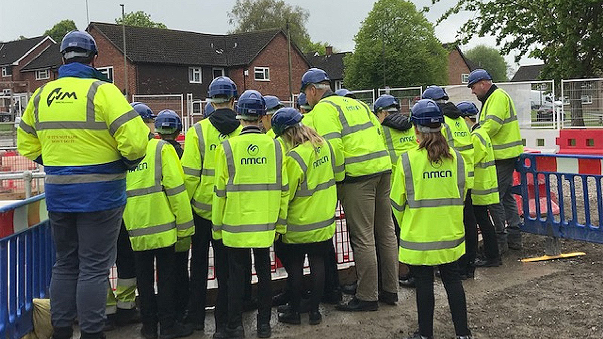
A visit by school children to the site – Courtesy of nmcn PLC
Lasting legacy and whole project impact
The entire construction phase was carried out in a prominent thoroughfare in the community with a high footfall of local residents and public being able to see the scheme. As a way to say thank you to the local community nmcn and Severn Trent invited the local school and residents to a public viewing of the shaft tank prior to lifting the cover slabs into place. This gave them the opportunity to witness the lasting legacy of our work and to inspire the future generations to consider a career in civil engineering.
Severn Trent and nmcn graduates and new starts were also invited to site to enhance their own construction knowledge.
On completion of the Kirk Hallam Flood Alleviation scheme a significant number of properties are now protected from sewer flooding and this societal benefit cannot be underestimated. Since the completion of the scheme in July 2019 there have been no reported flooding incidents.