
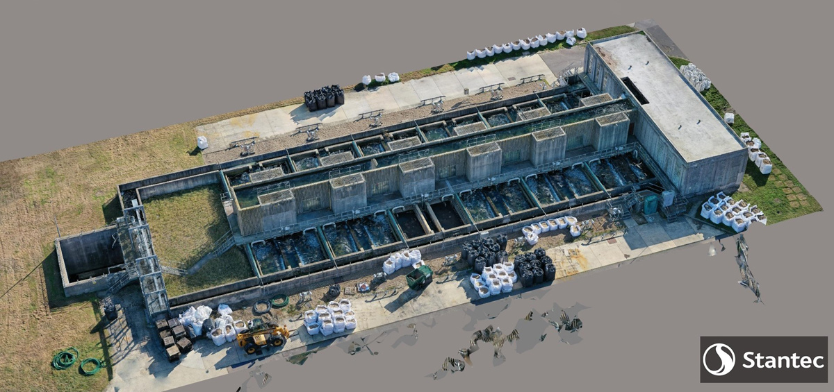
Layer WTW (2022)
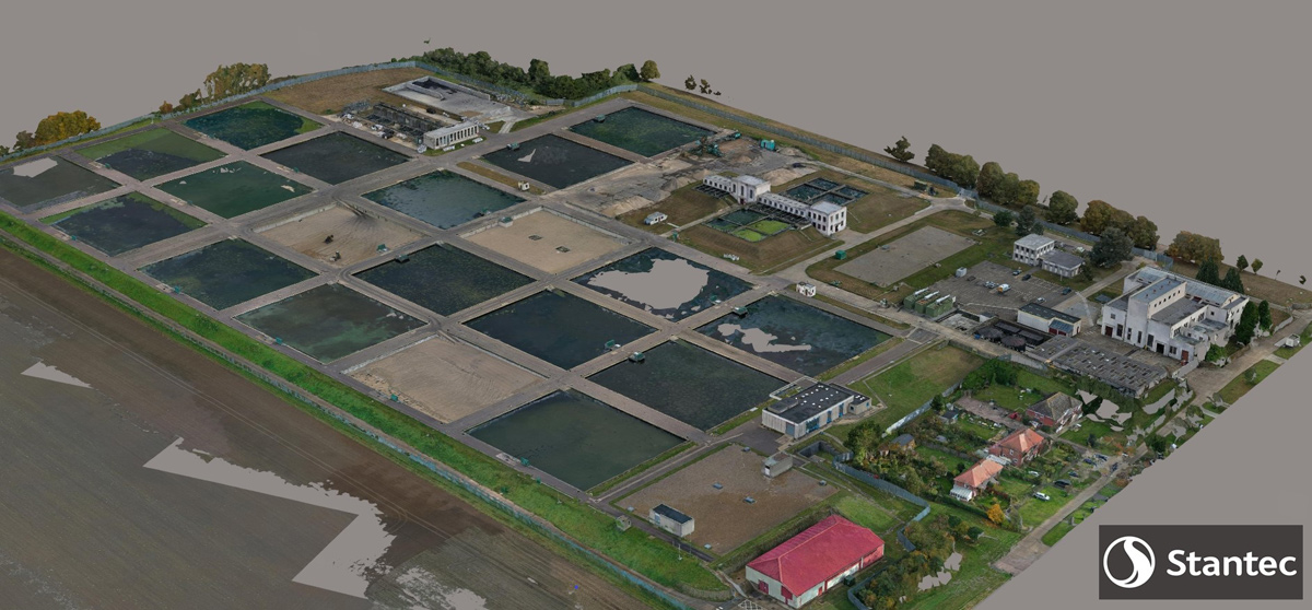
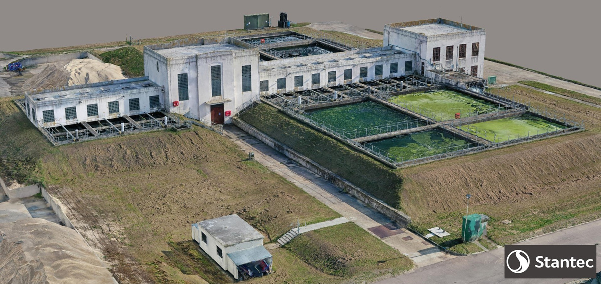
Overall site layout rendered in 3D - Courtesy of Stantec UK
Northumbrian Water’s Layer Water Treatment Works is located on site at Abberton Reservoir, just outside Colchester in Essex. It is the primal source of water treatment for the reservoir and produces clean drinking water for most of the north Essex region of Essex & Suffolk Water’s operating area, with a designed output of 145 Mld. To meet future demand and provide resilience, an enhancement scheme has been launched to increase output and improve reliability to the current designed output. The project will be a multi-million-pound investment spread over the next 3-4 years. Due to the nature of this work and the possible avenues in which it could go in terms of final design and investment, Stantec UK have been bought on board to help with the design process and create the tender documents for the construction contract.
Design issues
The issue with a site like Layer is purely the raw water quality, as this can fluctuate rapidly across a day; hence the need to enhance the capabilities of the site to continue to operate in all conditions efficiently. This poses a real problem – as Layer WTW is a slow sand works – and several different options need to be considered to create something that would be a best fit for the current site. For most water companies, an outage of a treatment works for several months (or possibly over a year) to create a brand new treatment works from scratch is not viable; both practically or financially. Stantec UK were employed to look into all available options for the site, without the need for shutdown for periods of time for consultation and design work to take place.
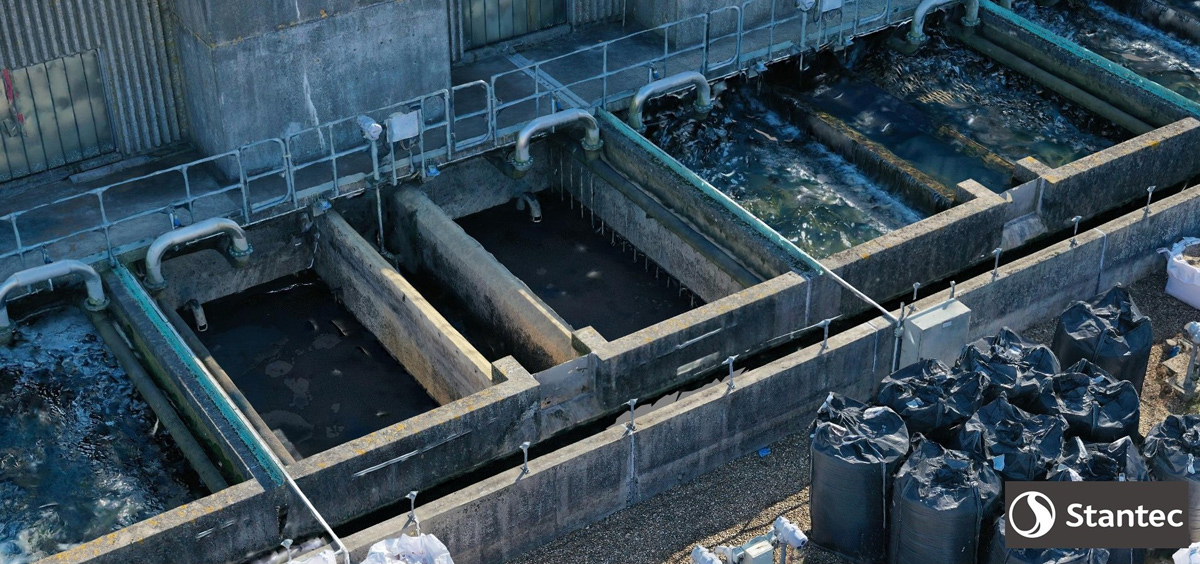
Screenshot from the model detail on the handrail and air pipes inside the filter can be seen – Courtesy of Stantec UK
Due to the current size of the treatment works being over 0.25km2 trying to design something new in addition to the current works, is a large undertaking. In order to carry out a traditional topographical survey of the site, including all of the existing buildings and treatment processes, would be a mammoth undertaking. The traditional technique of surveying this site would require the location of control points, which are fixed with GPS, GNSS and the ordinate survey data base. However, it would take at least 3 weeks and a team of several people to compete this task; not only just installing markers on objects of interest, but the site layout having complex shapes in buildings and roads to capture.
The other issue is that Layer is a live site with heavy machinery moving around all the access roads on site, in addition to the sand washer working in the sand yard. This adds a great level of concern over this task as from a health and safety perspective, not only with vehicles but also with the access onto the top of buildings – some do not have access, or have fragile roofs, making them inaccessible.
The nature of the site, with many buildings being built during a period of time when large overhanging areas, flat roof and cantilever protrusions (no longer safe by modern standards) were sought after, has created areas which cannot be accessed. Because of this, no traditional topographical survey will be able to gather the level of detail from the tops of these buildings, or accurately display this information.
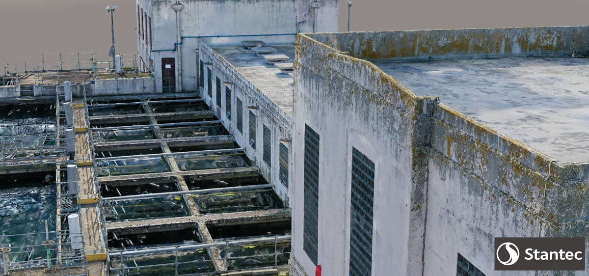
Even the moss can be seen but importantly the roof and vents (there is no access onto roof) – Courtesy of Stantec uk
Layer WTW Drone Surveying: Supply chain – key participants
- Design: Stantec UK
- ContextCapture software: Bentley Systems
- Mavic 2 Pro drone: DJI
- Photogrammetry software: Pix4D
Drone surveying
Stantec carried out a new way of topographical surveying using Bentley Systems’ ContextCapture software to collect the necessary control points. By utilising a DJI Mavic 2 Pro drone and Pix4D photogrammetry software for drone mapping to create customised flight plans, a whole site model could be created. Working with Peter Jackson from Stantec, a composite of flight routes was put together by flying at heights as low as 5m up to 40m, also changing the angle of the camera between 90° to 25°. Additionally, flight plans ranged from flying parameters, crosshatching and circular around objects such as complex shaped buildings.
The ContextCapture software is able to take the photos from the drone including the information within the file, such as the camera angle, height and GPS location. With this data, it uses photogrammetry, a process by which the software looks for shapes, angles, colours, and identifying features. Parallax, an old technique developed by astronomers, looks at an object from different viewpoints and given distances, its position, relative to other objects can be calculated. Using the file information, and by comparing them with other images, the software can begin to build a mesh, which once then takes the raw photos and overlays them onto the mesh to create a 3D image.
Patterson filter block taken out of the large model – Courtesy of Stantec UK
3D model
This 3D model then needs to be refined and placed in a geographical place. The control points, which would have been collected for both this and a traditional topographical survey, can be selected within the 3D model and have the GNSS data added. This contains both eastings, northings and more importantly height. Once this has been done the software is able to locate the model within a geographical space, but with the addition of the height the software is able to determine vertical distance between spaces and objects. This is done by using the same parallax technique used in the initial creation process, but by checking itself with known points, it can recalibrate the model and adjust the heights of buildings and landscapes. Additionally, the model can calculate volumes; for example the sand yard on site.
The software is able to use the mesh to calculate the volume in which it occupies, but this also works in the reverse, as there are areas of the site that will need to be filled as part of the potential works. From a designers point of view the actual volume of material required could be calculated with a couple of clicks of a mouse, informing a design without costly site visits of large calculations which could carry errors far greater than the 10mm differential of the model.
Boby filter block taken out of the larger model, GAC replacement in progress – Courtesy of Stantec UK
Over 10,000 images of the site were taken to produce the final product, which can be exported into AutoCAD for manipulation and design work in the traditional sense to take place. Overall the time spent on site gathering the data amounted to just three days, with two people. Much shorter than a team of several, over a period of weeks to complete the same task, and to a far less extensive area.
Benefits
This topographical survey has created a digital copy of the site externally down to 10mm accuracy. When future works are carried out, internal LiDAR scans can be added into this existing model to create a virtual site. Going one stage further, and integrating the SCADA system into a this visual platform, a true digital twin of the site can be created.
This has massive implications from a health and safety point of view, by sharing accurate location plans with contractors before coming to site. From an internal maintenance point of view, being able to see if a job requires working at height or scaffolding before even having site visits, will greatly help plan and budget for the future.
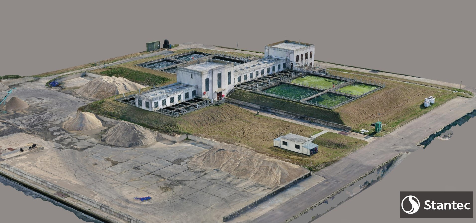
Sand yard with piles of sand that can be accurately measured – Courtesy of Stantec UK
Conclusion
The major short-term benefit from using this technology has allowed Stantec UK and NWG to look at the entire site and design different options very quickly and efficiently. The model removes the need to re-survey any areas that might have been missed or not captured as it was not considered to be part of the initial design, and allows for quicker designing and on the fly changes as deemed necessary by the team. Having this visual media allows for better explanation to key stakeholders. These benefits can be utilised in future projects of this type, not only providing a massive cost saving but producing ultimately a far better end product than could have been previously created.