Llyn Teifi Spillway Rehabilitation Works (2017)
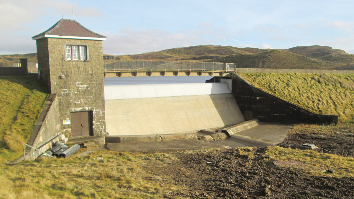
Llyn Teifi spillway downstream view - Courtesy of Dŵr Cymru Welsh Water
Llyn Teifi Reservoir is situated in a remote area on the western slopes of the Cambrian Mountains in Ceredigion, west Wales, and was created in the early 1960s by raising a natural lake. It is impounded behind six embankments constructed across natural low spots along its south-western margin, covering an area of just over 25 hectares and with a capacity at top water level of around 848,000m3. The main embankment is an earth embankment with a central concrete core, 160 m long and with a maximum height of 5m. It includes the main overflow and spillway.
Overflow and spillway
The overflow comprises a concrete gravity dam to the north end of the main embankment, formed between abutment walls and with a crest length of just under 19m. The draw-off tower containing the piped raw water supply and scour outlets is integral with the spillway structure and located immediately to its right (north).
The spillway is divided into three monoliths, the central one being slightly wider than the outer two. The downstream spillway face clearly shows that each of the monoliths was constructed in a number of separate lifts but the record drawings provide no details of either horizontal or vertical joint arrangements.
The original overflow comprised an ogee-type profile with a crest level 5 feet (1.52 m) below nominal embankment crest level and its vertical upstream face stepped back by 6 inches over its upper section. This was raised in 1997 through the addition of a simple ogee-type cast in situ extension doweled into the original crest. The extension was cast in three sections with the movement joints lined up with contraction joints below.
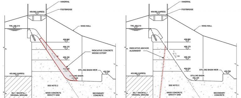
Typical cross section through overflow and spillway
Statutory inspection 2012
A Statutory Inspection under Section 10 of the Reservoirs Act 1975 was carried out on the 11 September 2012. In the report of that inspection, the following recommendations (among others) were made as to measures to be taken:
- Remedial works are undertaken to the concrete gravity section to control seepage paths, which are likely to be contributing to deterioration of the concrete and reduction in stability. As part of the investigation of options for this, the condition of the body of the concrete should be ascertained to determine whether any other works are required to arrest the deterioration of the concrete.
- In addition to controlling the seepage through the structure further works should be undertaken to improve the stability of the concrete gravity structure.
Seepage
The spillway has suffered significant seepage through various joints and defects with various attempts having been made to rectify the situation over the years. In 1984, the reservoir had been drained to allow refurbishment of both the upstream and downstream joint faces. However, by 2004, when Black & Veatch carried out an inspection, it was reported that:
“When water levels are high, the top two horizontal construction joints (about 400mm and 700mm below the underside of the recent crest raising structure) each show evidence of a direct seepage path, with spouts of water emerging during heavy wave action. Even with the water level 1.15m down during this inspection there was evidence of seepage from both of these joints”.
Concrete deterioration
The Black & Veatch report of 2005 also noted that:
“The exposed downstream face of the spillway has evidently deteriorated over the years, presumably due to the combined effects of seepage and surface weathering aggravated by the acidic water. There is no evidence on the main face of leaks self-healing through calcite deposition which indicates that the concrete matrix is in poor condition”.
The 2012 Statutory Inspection report recorded that:
“The concrete of the downstream surface of the overflow gravity section is reported by DCWW staff to be quite soft and in places can be gouged with keys”.
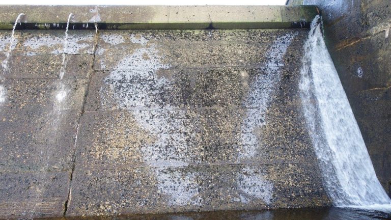
Evidence of both the continued seepage and joint deterioration particularly at the connection of the raised overflow section with the abutments (February 2016) – Courtesy of Stantec UK
Stability
The recommendation to further improve stability of the concrete gravity section was made on the basis of stability analyses carried out by Black & Veatch in 2005. These had concluded that although ‘major repairs are not required at this stage’ and ‘the factor of safety against sliding meets the acceptance criteria for all load combinations considered (except the sensitivity test where cohesion is reduced or disregarded)’:
- The factor of safety against overturning does not meet the acceptance criteria for Normal, Unusual and Extreme load combinations.
- Factors of safety against overturning are lower for the lower lift joints (e.g. varying from 1.17 for the first lift joint below the crest to 0.99 at the level of the stilling basin for the Unusual load condition).
Feasibility
In July 2014, Dŵr Cymru Welsh Water appointed MWH to assess options to satisfy the recommendations made in the Section 10 report and, in particular, to investigate the feasibility of installing a proprietary Carpi Tech geocomposite membrane on the upstream face of the structure to reduce both leakage and uplift forces.

Ice coverage on the downstream spillway face identifying seepage locations January 2011 – Courtesy of Dŵr Cymru Welsh Water
Constraints
A number of constraints were apparent from an early stage. The most significant was the requirement that all works be carried out with the reservoir at, or close to, its normal operating level. Llyn Teifi supplies around two thirds of the raw water to Strata Florida Water Treatment Works and it was decided that the risks associated with lowering the reservoir to any significant extent would pose too high a risk of supply interruptions, particularly if works were undertaken during the summer. In the winter months in particular, Llyn Teifi can become almost inaccessible due to snow and ice cover and at other times, being exposed, often suffers high rainfall and very strong winds.
Access for construction plant and equipment would also be difficult at any time of year, vehicular access being via a 1 km long private metalled track approximately 2.5m wide which leaves a winding minor public road around 4.5 km east of the village of Ffair-Rhos. The only access to the front face of the spillway would be via a steeply inclined section of rough track.
Together with the River Teifi, Llyn Teifi and the other Teifi Pools also comprise the Afon Teifi Special Area of Conservation (SAC). They also fall within the Elenydd Mallaen Special Protection Area (SPA) and Elenydd Site of Special Scientific Interest (SSSI). Any improvement works would therefore need the assent of Natural Resources Wales.
Site investigations
A diving survey by Edwards Diving Services Ltd confirmed that the overall condition of the upstream face of the spillway was reasonable and determined a reservoir bed level of around 4.6m below the overflow weir crest. The bed just upstream of the spillway comprised of a thin veneer of soft silt typically 30mm thick overlying a hard bed of gravels and cobbles.
Concrete investigations by Geotechnical Engineering Limited comprised a series of nine 100mm diameter cores drilled to a maximum depth of 200mm. These were distributed evenly across the spillway, with three on each block positioned at the top, middle and bottom.
Testing was carried out by ACS Testing Ltd and Sandberg LLP and suggested that, contrary to earlier suggestions, the concrete was in reasonable condition with a good level of compaction and no evidence of cracking/fissures or honeycombing.
Stability assessment (2005)
The stability analyses by Black & Veatch in 2005 identified that the factor of safety against overturning did not meet the acceptance criteria for Normal/Usual, Unusual and Extreme load combinations as set out in ‘Design of Small Dams’ published by the United States Bureau of Reclamation, 1987 and reproduced below:
- Normal/usual: Normal design reservoir elevation with appropriate dead loads, uplift, silt, ice and tailwater. If temperature loads are applicable to the specific sites, use minimum usual temperatures occurring at that time.
- Unusual: Maximum design reservoir elevation with appropriate dead loads, silt, tailwater, uplift, and minimum usual temperatures occurring at that time, if applicable.
- Extreme: The usual loading plus the effect of the maximum credible earthquake (MCE).
Table 1 (below) sets out the specific parameters adopted. Table 2 shows selected results from the analysis of the overturning stability of the central monolith, noting that the factors of safety against sliding were all found to be acceptable.
Tables 1 and 2
Stability assessment (2015)
MWH updated the 2005 stability analysis with stability checks as described in the more recent guidance from the US Army Corps of Engineers, ‘Stability Analysis of Concrete Structures’ (EM 1110-2-2100, 2005).
Table 3 (below) sets out selected results of this analysis for comparison with Table 2 (above). Table 4 (below) shows the loading combinations considered.
It can be seen that, using the more recent guidance, sliding represents the critical case with factors of safety well below those required for both extreme (flood) and extreme (seismic).
Tables 3 and 4
Options evaluation
It was recognised from an early stage that installation of a carefully designed, waterproof geocomposite membrane to the upstream face of the Llyn Teifi spillway should address the leakage issues. However, particularly after the diving survey, it was also recognised that it would be difficult to take the membrane down to below the lower lift joints which had the lowest factors of safety against sliding.
Two main complementary options were therefore considered:
- Option A: The addition of a concrete wedge to the downstream face of the spillway: Infilling beneath the overhang of the raised weir and effectively negating the need to patch repair degraded areas of concrete to the downstream spillway face.
- Option B: Post-tensioned anchors: This scenario assumed that ground anchors would be drilled from 406.5m OD on the downstream face at an angle of 80° to the horizontal and giving a tension of 40kN/m run of the structure.
The concrete wedge, in conjunction with the upstream geocomposite membrane, was selected as the preferred option due to the problems and costs anticipated in getting construction plant to the working face for a small number of anchors, the likely need for removal and replacement of the footbridge and because of the on-going requirement for inspection and testing of these.
Solution design
Detailed design of the concrete wedge was undertaken by MWH with Carpi Tech appointed as a sub-consultant to develop proposals for the upstream geocomposite membrane.
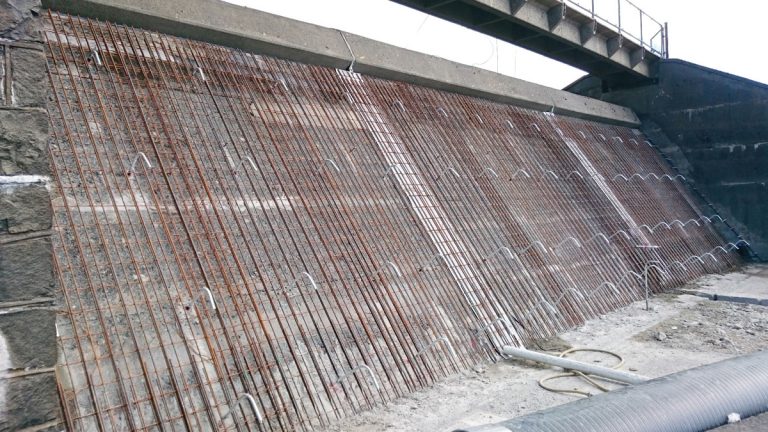
Reinforcement placement – Courtesy of Kaymac
Concrete wedge: Design of the wedge was carried out using STAAD Finite Element Analysis software, in accordance with Eurocode 2, assuming a PMF top water level of 408.86m and a reduced factor of safety of 1.2 reflecting the extreme nature of such an event.
This required that 25mm diameter galvanised high tensile steel L-shaped bars be drilled and fixed into the downstream concrete face of the existing spillway on a typical 1200mm square grid using Hilti HIT-RE 500-SD chemical anchors with an embedment length of 600mm. Dowels were also drilled vertically into the base of the existing spillway and into the abutment walls.
Reinforcement for the wedge itself was designed to be continuous over the full width of the concrete spillway and comprised a single layer of B1131 mesh to each face supplemented with B16 bars at 200mm centres. A 500mm wide proprietary drainage layer with perimeter hydrophilic waterstops was specified to be applied the full height of each of the existing vertical spillway joints with 100m diameter drainage pipes running through the base of the new concrete wedge.
Geocomposite membrane: The system proposed by Carpi Tech for the upstream face of the concrete overflow section comprised a tensioned geocomposite liner (SIBELON® CNT 3750) prefabricated from a watertight PVC geomembrane 2.5 mm thick, heat-bonded during extrusion to a non/woven, needle punched geotextile to provide anti-puncture resistance and drainage. This would be mechanically fastened to the overflow structure using a Carpi Tech patented system and lapped and heat-seamed on site in accordance with the design details and allowing for installation underwater by divers.
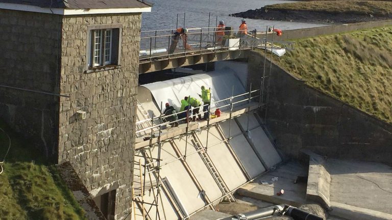
Liner installation over weir crest – Courtesy of Dŵr Cymru Welsh Water
At Llyn Teifi, the design included three separate ‘compartments’; a main central compartment over the full width of the concrete spillway and two smaller compartments to each of the upstream abutment wing walls. The right hand abutment wing wall which incorporated a masonry facing would have additional protection in the form of a second layer of anti-puncture geotextile.
Each compartment included a drainage system to allow any water trapped in the interface of the liner and the existing structures to be separately discharged via a common outlet point to be drilled through the base of the concrete spillway structure.
Construction
The contract for construction of the works was awarded to Swansea-based Kaymac Marine and Civil Engineering Ltd with Carpi Tech as a subcontractor to install the liner system. Site works commenced on 12 September 2016 after access road improvements carried out over the summer by Dŵr Cymru Welsh Water.
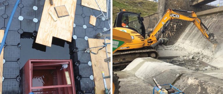
(left) Limpet dam and modular floating pontoon and (right) Concrete removal at foot of existing spillway – Courtesy of Dŵr Cymru Welsh Water
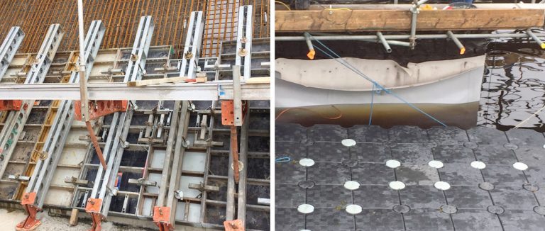
(left) Formwork to downstream spillway face and (right) liner installation to right hand abutment – Courtesy of Dŵr Cymru Welsh Water
Kaymac’s first task was to core drill a 175mm diameter hole through the base of the existing spillway structure, install and grout in the gravity drainage pipes for each of the three liner compartments. To facilitate this Kaymac designed and fitted a limpet dam to the upstream face of the spillway using a floating modular pontoon, thereby allowing all works to be undertaken in the dry.
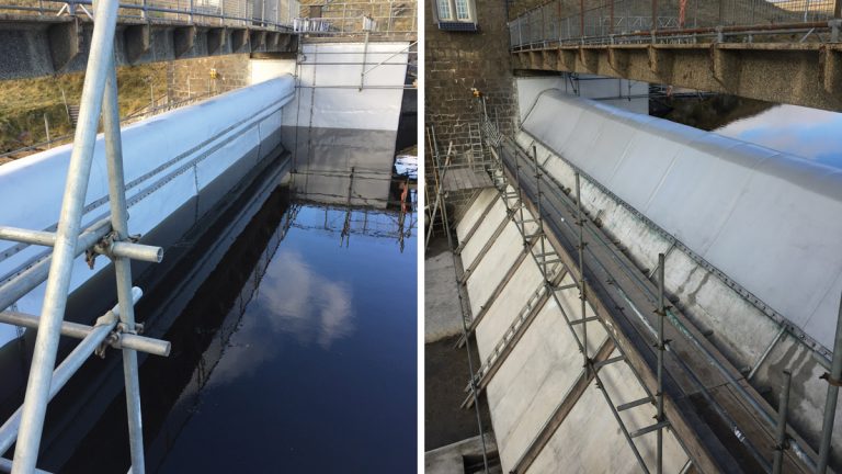
(left) Liner installation to spillway and right abutment and (right) Completed concrete wedge and liner installation over weir – Courtesy of Dŵr Cymru Welsh Water
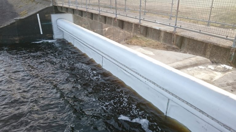
Completed works – Courtesy of Dŵr Cymru Welsh Water
After breaking out of some existing concrete at the foot of the spillway and placement of reinforcement a proprietary formwork system designed by RMD Kwikform was used for construction of the concrete wedge. This allowed the works to be completed in three vertical lifts using a concrete pump situated on ground to the north of the reservoir some 40m away. Carpi Tech, with divers from their partner, Lucatelli Diving of Trieste, commenced installation of the waterproofing liner on 1 November 2016. All construction was successfully completed before Christmas 2016.