
MAC Extensometer (2017)
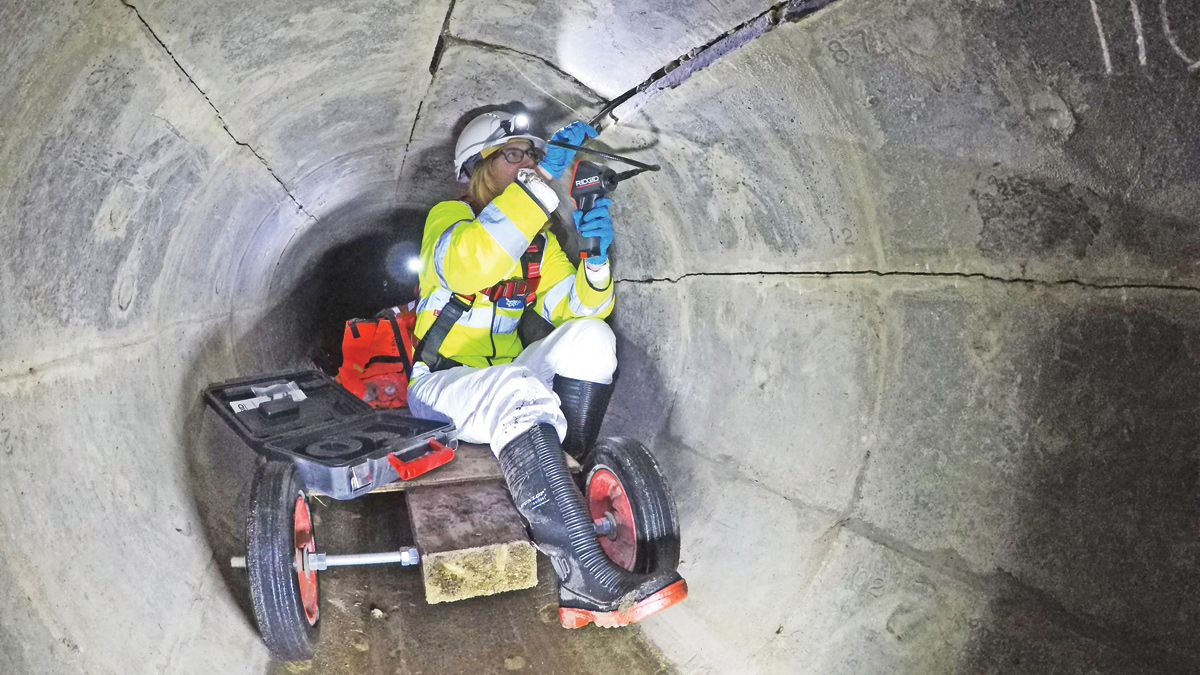
Figure 1: Hydraulic overloading causing liner displacement - Courtesy of Wessex Water
The UK has a tremendous legacy of tunnel construction over the last 150 years, from Joseph Bazalgette’s brick sewers in London, through to reinforced concrete designs based upon early engineers such as François Hennebique. Wessex Water has a considerable cumulative metreage of tunnels constructed over the last 150 years, up to 5 metres in diameter, serving over a million customers in Bristol, Bath and the Poole/Bournemouth/Christchurch conurbation. As part of a structural survey programme, Wessex Water looked for a predominantly non-destructive testing (NDT) method of analysing the structural capabilities of the tunnels and understanding their longevity. In 2016 Wessex Water became the first UK WaSC to use the IKT MAC System (Mécanique d’Auscultation de Conduits) for such an assessment of the structural condition, of a man-entry concrete sewer in Bournemouth, and its host geology.
The MAC system
The system was devised initially by Eau de Paris to target the repair of deteriorating large diameter sewers, recognising that both the stability of the pipe and of the surrounding soil needs to be understood to determine where remediation is required. The technology was further developed by IKT (Institute for Underground Infrastructure, Germany) over three years, to the point where it was first deployed for commercial use in Spring 2015. Its first major deployment was for Hamburg Wasser to survey 450m of an oval masonry sewer (DN 1700/2000).
With the advent of a device such as the MAC Extensometer, the stiffness of constructional materials can be determined, aided by coring and unconfined compressive testing, to establish a more thorough non-destructive test regime, augmented by finite element analysis, that will allow understanding of the tunnel lining capabilities under given loads and in a particular geology.
The MAC System comprises a powerful hydraulic pressure cylinder, which forces two bearing plates, simultaneously against opposite walls of the tunnel, automatically controlled, with pressures ranging from 10 to 100 KN. Fine sensors (Extensometers), measure the deformation arising directly in the area of the pressure plates and at a distance of approximately one metre in front and behind these points to record the three-dimensional deformation. Despite the high forces applied, the automatic control of the pressure cylinder prevents any overloading and damage to the tunnel walls. The actual deformations measured are, at most 0.5mm (Figure 2).
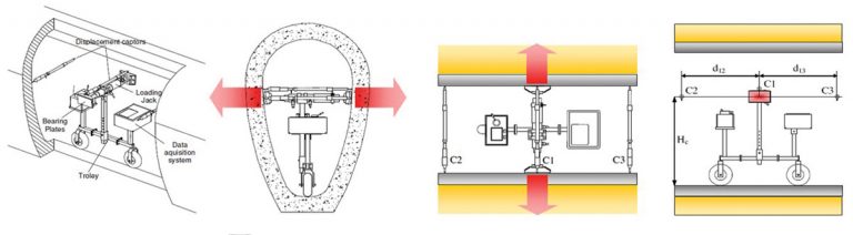
Figure 2 : Diagrammatic MAC layout – Courtesy of Wessex Water
The rate of loading is approximately 5KN/s. The deformation of the horizontal diameter is limited to a minimum of 0.025% or 500μm. The inventor, Dr. Olivier Thepot, states the entire system is of variable geometry and can be adapted to all shapes of sewers and tunnels. Three measurements are obtained, the force pushing on the bearing plates, the displacement measured by the main rod and the displacement measured by the 3-dimensional rod.
This data is collected and analysed, instantaneously displaying a graph on the data logger showing the force/displacement curve across the pipe, and the damping of the displacement in the longitudinal direction. From readings, it is possible to calculate two parameters; the global stiffness which is equal to the ratio between the force and the main displacement and the damping factor, which is equal to the ratio between the 3-dimentional displacement and the main displacement.
Cores are then taken through the tunnel lining to determine the mechanical properties of the structure. These cores are crushed for unconfined compressive strength (UCS) in terms of N/mm2. In addition, it is imperative to establish the external geology/lithology via a borehole, with a range of in situ and laboratory tests. When the geometry of the pipe (shape and thickness) is known, it is possible to back calculate the Young’s modulus of the soil (ESoil) and the Young’s modulus of the structure (EMaterial).
Working with the Institut Für Geotechnik (IGtH) der Universität Hannover through Wessex Water’s partners IKT in Germany, a Finite Element Model is then created.
IKT developed the system for use in sewers from DN 1200 to DN 3000 and it now works in a half-automatic mode to improve safety at work. At certain limits of force and displacement, hydraulic power shuts off. Furthermore wireless data transmission makes testing in a sewer much easier. The benefits of the MAC system are:
- Identifies the weak point in the pipe-soil-system.
- Determines whether the pipe or the surrounding soil is the cause of weakness.
- Predominantly non-destructive.
- Equipment is portable and can be assembled via man-access chambers.
- Core drilling in the sewer wall and bores in the surrounding soil are reduced to a minimum.
- Determines whether repair is feasible.
- Facilitates targeted refurbishment and subsequent checking of its effectiveness.
- Success of repair can be verified.
- Changes in stability can be investigated over long periods.
- Considered by the client to be cost-effective.
Analysis of ‘Flexilok’ tunnel in a deep saturated sand geology
The MAC system was used for the first time in the UK by Wessex Water (YTL E&C) in the summer of 2016, at Braidley Road, Bournemouth.
The tunnel in question was constructed in 1971 through a dense sand geology at a depth of 19m. The geology of Bournemouth is typified by wind-blown, coarse and fine hygroscopic silver sands, which are, usually well cemented, but can be prone to degrees of migration when saturated. The Flexilok tunnel lining is an unbolted ring of concrete segments best suited to the over consolidated London Clays which ‘squeeze on’ to the extrados of the newly constructed ring when the shield moves forward, and exposes the annular over cut, represented by the thickness of the shield.
At some point over the last few years, the Braidley Road tunnel has been hydraulically surcharged and the water pressure has forced the segments out, over a 70m length, mid-way along the tunnel (Figure 1). For the first time the MAC Extensometer has given Wessex Water the ability to understand the structural capability of the tunnel lining, which was assumed would vary along its 220m length, between shafts. By iteratively analysing the tunnel in discrete lengths, Wessex Water was able to understand the potential longevity of the tunnel (Figure 3).
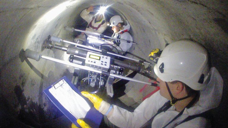
Figure 3 : Extensometer in tunnel – Courtesy of Wessex Water
MAC conclusions and least cost tunnel repair
Of the total 220m length of tunnel that was measured, the visually defective range exhibited by the segment deformation between a chainage of 100-140m (Figure 4) and to compare to what was thought to be competent lining, Wessex Water measured from 70–100m and a second range upstream of the defects at 140-170m. In actual fact, the external stiffness in the two base line zones indicated a lower stiffness value, proving loose sand, whilst the deformation zone was in either compact or very compact zones.
It was concluded that the grouting at springing level in the deformed zone provided adequate lateral support as viewed by an endoscope survey where possible, and the remainder of the tunnel exhibited the propensity for failure. Although this was not expected, it does indicate the worth of the system in understanding the likelihood of future collapse.
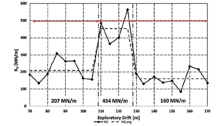
Figure 4 : Pipe-soil stiffness (Kg) with zoning (2) – Stiffness results linearly along the tunnel length – Courtesy of Wessex Water
A lining solution was designed utilising 1050mm ID liners SRM Type 1 ‘Fully Deteriorated’ conditions and a liner thickness was devised at 35mm, cross-referenced to the American standard ASTM F1216 :09 (Now ASTM F1216 :16). The linings were procured from Amiantit and manufactures in single piece from their Polish factory.
The scheme was completed to programme over a six week period, including a plasticised intergrout between host lining and extrados of the Type 1 shells, by the contractor Matt Durbin Associates Ltd, at a total cost of £365k (Figure 5).
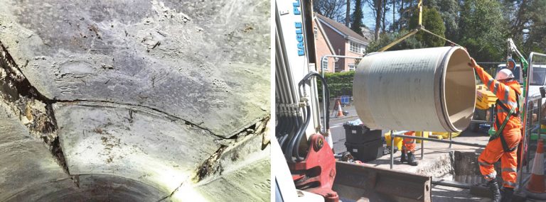
(left) Braidley Road – Typical defect and (right) Figure 5 : GRP Type 1 Shell installation – Courtesy of Wessex Waterter
In summer 2017, the MAC Extensometer will be used on a similar section of tunnel known as the Southern Foul Water Interceptor (SWFI) in Bristol; constructed with the same linings in 1973. Although that tunnel was constructed in part through the Redcliffe Sandstones and Mercia Mudstones, which should offer a high degree of lateral support to the tunnel, there was a collapse at the Tannery in 1998, as it is routed adjacent to the New Cut; a diversion channel constructed in 1817 for the River Avon.
This system allows the owners of tunnels, whether for sewerage, railway, cables, whatever, to target the available maintenance or capital funds, on the most deserving assets. It also means reduced frequentative man entry, which mitigates concerns of health and safety, and satisfies the insurers of such structures, that they are insurable, and premiums are balanced and appropriate.
Fundamentally, the MAC system allows perceived structural problems to be analysed, along with structural elements which are not showing signs of distress.