
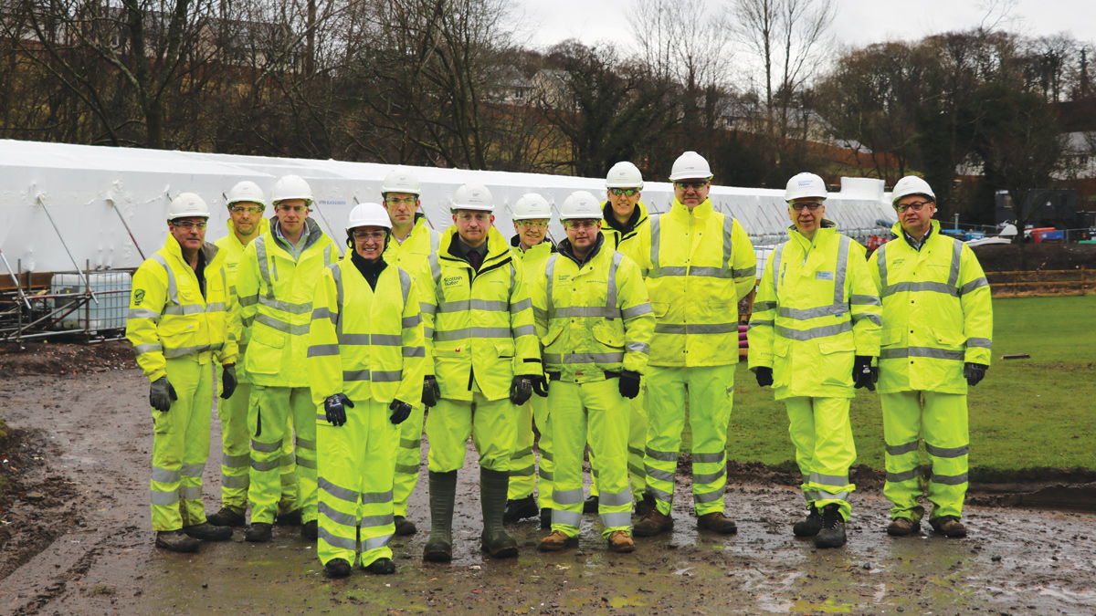
Roundknowe CRFP (2020)
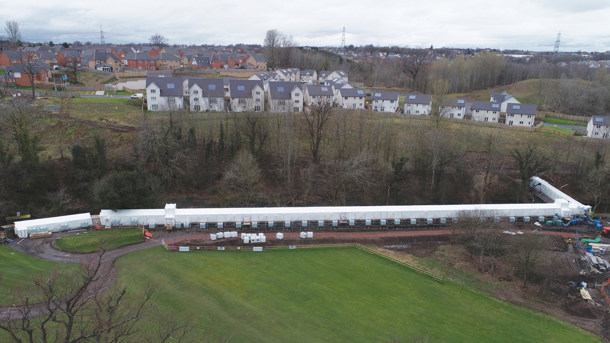
Roundknowe encapsulation tent 1 - Courtesy of aBV
In 2017, aBV – a joint venture between Amey and Black and Veatch (now Binnies), and Environmental Techniques approached client Scottish Water about utilising carbon fibre (CFRP) and glass fibre (GFRP) to provide a 60-year rehabilitation technique to an existing pipe bridge; an approach that has never been used before in the UK Water Industry. Traditionally, pipe bridges are replaced, but this one was located on an environmentally sensitive area on a golf course. One of the benefits considered was a much-reduced impact compared to the standard construction process with minimal over-pumping required. The CFRP/GFRP system provides a robust, sustainable solution that creates a new pipe. After receiving the initial estimates, which included a 10% savings in cost and a 25% reduced on-site construction time, the client elected to move forward with the CFRP/GFRP design option. Nevertheless, this began an 18-month approval process for the CFRP and GFRP systems through rigorous assessment by Scottish Water’s Technical Support & Assurance team along with aBV Design Engineers. This paper will focus on two major aspects of this project: (1) the engineered solution, and (2) the quality and expediency of the installation to meet the client’s timeline.
Introduction
In Scotland, much of the aerial piping was built in the mid-20th century and is approaching the end of its design life, with some showing significant signs of failure. Many of these pipes have previously been patched, but the repairs are now failing, causing the potential for leakage, including into any adjacent watercourse. Aside from this, the locations of these assets are often difficult to access and can pose environmental and engineering challenges. The use of carbon fibre (CFRP) and glass fibre (GFRP) reinforced polymers has been considered as a both time and cost-effective rehabilitation technique to directly address the problems that arise from conventional methods. Some the advantages include:
- Low site footprint, which makes it ideal for different locations.
- Low environmental impact whilst minimising the need for over-pumping.
- Allowing the pipes to remain in service.
- Quicker installation time.
- Reduced costs compared to traditional rehabilitation techniques, i.e. complete replacement and cured-in-place (CIPP).
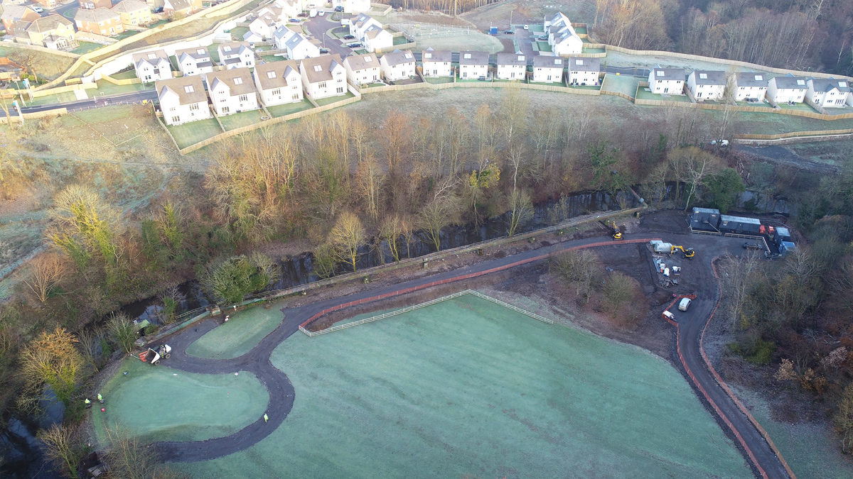
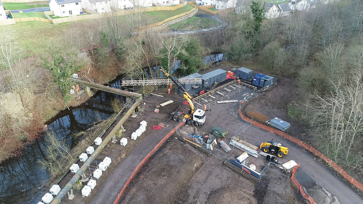
Construction ongoing on the Roundknowe site within the Calderbraes Golf Course – Courtesy of aBV
Roundknowe Project
For the project at Roundknowe in Scotland, UK, utilised a solution to rehabilitate the steel aerial pipelines with minimal disruption was required by the client. The site itself is bounded by a housing development, a farm and a golf course. It also crosses a watercourse on two occasions into woodland, which is home to both otters and bats. It was essential to reduce the duration and impact of the project, which meant those who would usually be directly affected by the project installation were not, and their usual services remained intact for the entire project duration. For ease of access, the golf course did agree to weekend only play at one of the holes for the duration of the project. The entire timescale of this project was 24 weeks, which started in late October 2018 and completed in May 2019; during the off season of the golf course.
Engineered solution
When the CFRP/GFRP solution was first proposed by aBV and Environmental Techniques, it was something that Scottish Water had never considered as a potential solution to the remedial work required for their aging pipe bridges. It is widely known throughout the trenchless solution market that CFRP/GFRP can be utilised for internal repair of pipelines, but it had never previously been used externally in the UK and so an 18-month technical review process of the material and design calculations was required. The first step in this review process was to determine the design parameters for the pipeline. Below was the design information provided:
- Pipe type: Steel.
- Pipe diameter: 920mm.
- Gravity pipeline: No internal pressure.
- Pipe span between supports: 15.3m (assumed worst case).
- Temperature change: -16 °C to 31°C.
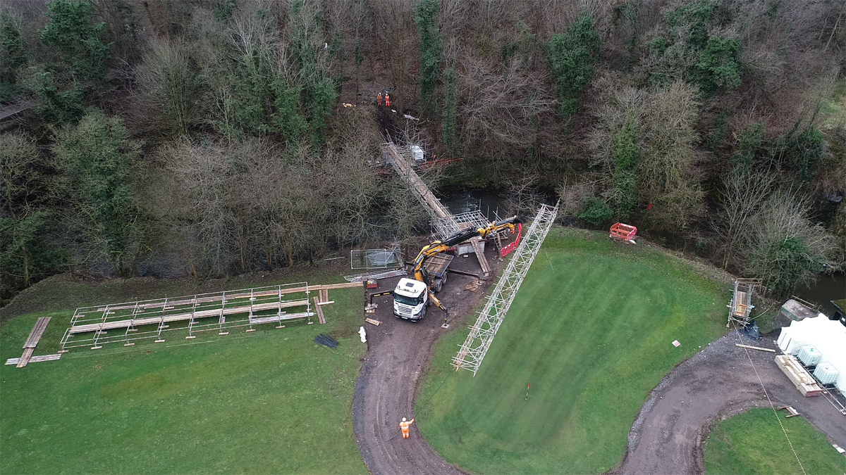
Roundknowe – pipe bridge installation – Courtesy of aBV
Once the project criteria were specified, it was crucial to determine the appropriate design methodology. Since there is no recognised UK standard for CFRP/GFRP repairs of aerial pipelines, it was decided to design the CFRP/GFRP system using specifications laid down in the American Water Works Association (AWWA) design standard C305 [AWWA C305]. This standard was developed specifically for strengthening Pre-stressed Concrete Cylinder Pipe (PCCP) using CFRP. Thoroughly reviewing and understanding the design specification within the document strongly influenced the primary design considerations for this project. In the end, four different design checks were required for the CFRP System:
- Localised stress due to the support system.
- Buckling of the CFRP liner due to temperature change.
- Deflection limitations due to moments spanning between supports.
- Debonding of the CFRP system due to shear demands at the termination locations.
These design calculations were thoroughly reviewed by aBV and Scottish Water, and after several review sessions, the material and design approach were deemed acceptable for the project. A controlled design query log was produced and maintained by Scottish Water to ensure that all technical queries and demands were noted and solved prior to acceptance and implementation. The technical acceptance criteria ensured the problem was clearly defined and the solution was technically sound.
Nevertheless, the design portion of the project did not end there. Since the CFRP/GFRP systems were going to be externally wrapping pipe bridges, there were several detailing challenges that came about. In the end, this became a crucial part of the pre-project design process. The different obstacles included:
- Roller supports/pier locations.
- Joint locations.
- Flange connections.
- Repair locations/FlexSeal coupler.
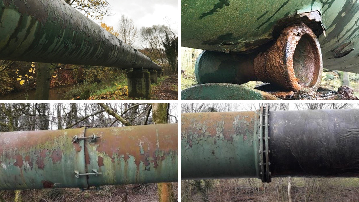
On-site obstacles (top) roller supports and (bottom) joint locations and flanges connections which required special detailing – Courtesy of aBV
With the locations of special detailing identified, the modified installation sequence was as follows:
The pier locations
- Support pipe with temporary supports to remove roller and allow space for CFRP installation.
- Wrap around existing pipe as per normal design.
- Install new bearing support and remove the temporary supports.
For the joint location
- Remove the bolts to create a smooth surface of the pipe. The CFRP system will act as a bolt when installed.
- Apply 1 layer of the GFRP system in the hoop direction.
- Apply 1 layer of the GFRP system and CFRP system for additional longitudinal strength.
- Remove steel straps.
- Apply 2 layers of the CFRP in the longitudinal direction, per plans.
- Apply 2 layers of the GFRP system in the hoop direction, per plans.
- Apply top coat as required.
For the repair and flex-seal coupler locations
- Create a 4:1 transition slope with thickened epoxy or epoxy mortar.
- Apply system as per project requriements over the transitioned area.
- For repair areas that do not have any transition, the surface was prepared as requried and the CFRP/GFRP System was applied per the project plan.
External scaffolding and encapsulation of the pipe – Courtesy of aBV
Site set up
When completing an external wrap of an aerial pipe using CFRP/GFRP systems, there are several site set-up requirements that had to be completed before the wrapping of the system could commence.
- Mobilising to the site: The crew itself was from the US, (there being no such skilled personnel in the UK), therefore visas needed to be co-ordinated appropriately. Additionally, the materials needed to be imported from the US, (there being no UK source), which required allowance to be made for the 6-week shipping timeline.
- Due to the remote location of the pipeline, access needed to be created: Even though the footprint is small for the CFRP/GFRP element of project, extensive manhole upgrades were required, and this needed temporary access roads. The storage and mixing of the resin, and the saturation process, all need to be done in a temperature-controlled environment to ensure the system cures properly.
- Set-up of external scaffolding: Since the pipe is above ground more than a metre, external scaffolding was required to ensure the CFRP/GFRP system could be wrapped externally with expedience without hindering quality.
- Encapsulation of the pipe: Having a controlled environment for temperature and humidity is required to ensure the proper cure of the CFRP/GFRP system. This is especially important for this project, due to the extreme temperature and wind possibilities.
Roundknowe CRFP Project: Supply chain – key participants
- Client: Scottish Water
- Alliance partner: aBV (Amey Black & Veatch)
- Tier 1 contractor: Environmental Techniques
- CRRP wrap: Aegion/Environmental Techniques
Roundknowe – pipe bridge installation – Courtesy of aBV
Installation
Once the site set up was complete, installation could begin.
- Installation of cured-in-place pipe: In addition to the external CFRP/GFRP there is an internal CIPP portion of this project. The CIPP system was installed prior to the application of CFRP/GFRP system due to a section of the pipeline being buried along the back of a putting green on the golf course.
- Surface preparation: This includes cleaning and sand blasting the pipe. This ensures that the new material bonds firmly and appropriately to the existing pipe. This was achieved through requiring surface preparation to be a minimum of SSPC-10 and all rust and external debris had to be removed. Immediately this was done, the pipe was coated with a layer of epoxy to prevent flash rusting.
- Installation of the CFRP/GFRP System: Based on the design calculations, the installation of the CFRP/GFRP system was applied in the following order:
- GFRP layers in the hoop direction for structural strength and to act as a dielectric barrier.
- CFRP layers in the longitudinal direction to resist deflection loads and thermal issues.
- FRP layers in the hoop direction for additional structural strength and encapsulation of the CFRP system.
- A fire retardent layer and topcoat of green paint was applied to the system.
- Areas requiring special detailing: Based on the items identified during the site investigation, the areas requiring special detailing were wrapped according to the specific design at each location.
- Removal of all site set-up: This included removal of the scaffolding and encapsulation. Also, the site compound and access road were removed, and the landscape was reinstated to enhance its pre-site condition. A specialist landscape contractor was employed to ensure that the golf club requirements were met.
Since this was the first project for Scottish Water, the Quality Control/Quality Assurance (QA/QC) aspect of the project was critical. The QA/QC measures that were implemented during the project included continuous monitoring of the temperature and humidity, and Shore D Hardness testing to ensure the complete cure of the CFRP/GFRP system.
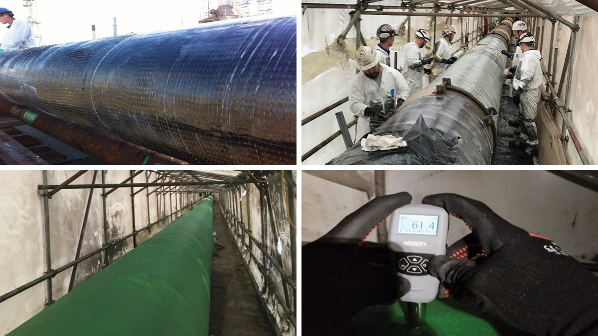
(top) Examples of installation of CFRP/GFRP System and (bottom left) completed installation and (bottom right) Shore D hardness testing – Courtesy of aBV
Conclusion
The project was constructed in 24 weeks between October 2018 and May 2019) and was 10% cheaper than conventional methods. The use of CFRP/GFRP as a new rehabilitation technique had direct benefits to all stakeholders.
Scottish Water enjoyed reduced risks of liability for contamination and environmental damage from over-pumping as well as saving money versus previous similar projects. Contractors spent 25% less time on site meaning greater capacity to effect further projects as well as the statistical reduction in the likelihood of industrial accidents that results from shorter on-site time. The reduction in timescale benefits the end user, due to minimal service interruption and reduced construction noise. More widely, the golf club, local road users and the natural environment and ecosystems were interrupted over a 25% shorter time and with a much-reduced impact due to this and the less invasive technique.
Even though weather in Scotland can be challenging for application of CFRP/GFRP systems, this project helped to show that it is possible to carry out through encapsulation and monitoring during installation. At the end of the project, the client was supplied a QA/QC report providing additional assurance of the quality of the installation. With this project having a detailed and forensic review process, the Technical Acceptance has laid the groundwork for future pipe bridge rehabilitations.
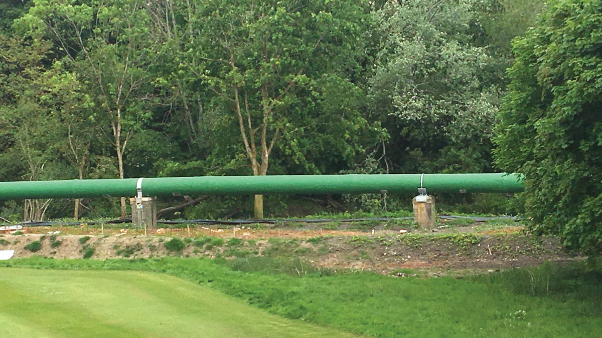
Completed pipe- Courtesy of aBV
Scottish Water Director of Capital Investment Mark Dickson gave the following feedback: “The CFRP is one of the best examples of innovation that I have seen on the capital programme in SR15 and I am really keen to see this solution become part of our standard approach on the rest of the programme”.