
Shieldhall Tunnel (2016)
Section of TBM lowered into Shaft 1 - Courtesy of SNS
Construction of the Shieldhall Tunnel, the biggest investment in the Glasgow wastewater network since Victorian times, is well underway. Once complete, it will improve river water quality and the natural environment of the River Clyde and its tributaries, enable the Greater Glasgow area to grow and develop, alleviate sewer flooding key locations and deal with the effects of increased rainfall and climate change in the area served by the Shieldhall WwTW. The Shieldhall Tunnel will be 3.1 miles long (more than five times as long as the Clyde Tunnel that takes a dual carriageway beneath the river) and 4.70m in diameter, big enough to fit a double-decker bus inside. It will be the biggest wastewater tunnel in Scotland, with a storage capacity equivalent to 36 Olympic-sized swimming pools.
Planning
The investment follows years of collaboration and studies by the Metropolitan Glasgow Strategic Drainage Partnership (MGSDP), whose members include Scottish Water, the Scottish Environment Protection Agency (SEPA), Glasgow City Council and Scottish Canals.
The improvements are required to meet European directives and SEPA recommendations and will contribute towards the Scottish Government’s objective to comply with the Urban Waste Water Treatment Directive and to achieve Water Framework Directive ‘good ecological status’ or ‘good ecological potential’ for more than 40 miles of the River Clyde and its tributaries.
Undertakings
The team involved in the Shieldhall Tunnel for Scottish Water, known as the Glasgow Tunnel Partnership, is a commercial joint venture between Costain and VINCI Construction Grands Projets (CVJV).
CVJV have been carrying out preparatory work, including mine working consolidation, utility diversion work, constructing the first shaft, service chamber, cut and cover and the tunnel boring machine (TBM) launch chamber at Craigton in advance of tunnelling beginning.
Tunnel route
The tunnel is being launched from a former tram depot site in the Craigton area of Glasgow, in the south-west of the city. The route of the tunnel will go under Bellahouston Park, Pollok Park, beneath Titwood Road and then under Queen’s Park where it will connect with the main sewer system. A shaft will be sunk at Queen’s Park to allow the TBM to be recovered when the tunnelling is completed.
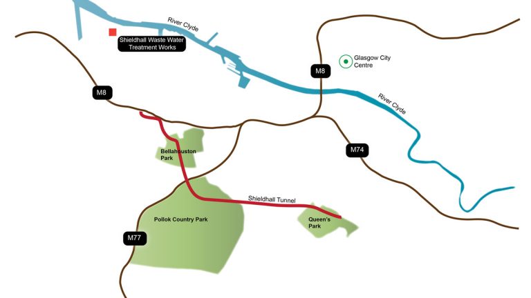
Route of tunnel – Courtesy of Scottish Water
The route for the tunnel will take advantage of the large amount of parkland and the wide roads on Glasgow’s southside. This was selected to cut down on noise and other disruptions to the area’s businesses and residents.
New roadway
The launch site is very close to local housing, the M8 motorway and the rail commuter line to Paisley. One of the first tasks for the team was to build a new roadway for the lorries removing the spoil from the site to minimise noise for nearby residents.
The existing access roads within Craigton area could not accept the additional 100 lorries per day necessary for servicing the TBM works. All supplies (concrete segments, pipes, cement, bentonite, rails) and excavated materials are routed through the Craigton main compound.
Ground conditions
Running a tunnel under a major city inevitably means problems for the project team and the Shieldhall Tunnel is no exception.
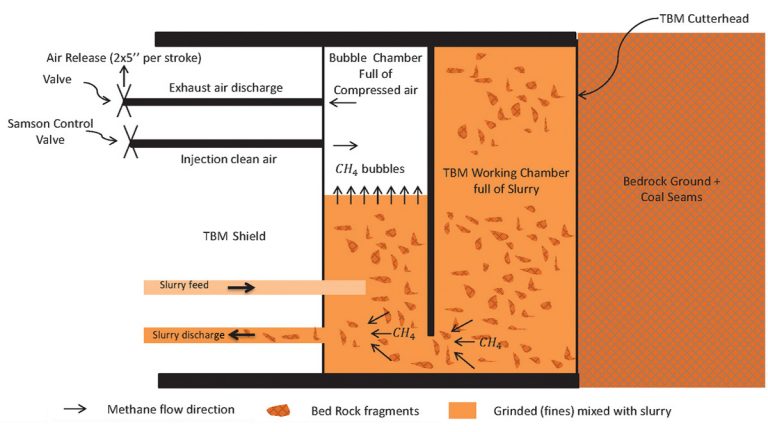
How the TBM’s sealed chamber cutting head operates – Courtesy of Scottish Water
- Ground conditions combined with the shallow depth of the tunnel means this project in terms of tunnelling techniques has it all; piled shafts, top down constructed shafts, sprayed concrete linings, pipe jacking, grouting, cut and cover and bored solutions.
- There was contamination in the soil from the tram works and this had to be removed before any work could begin.
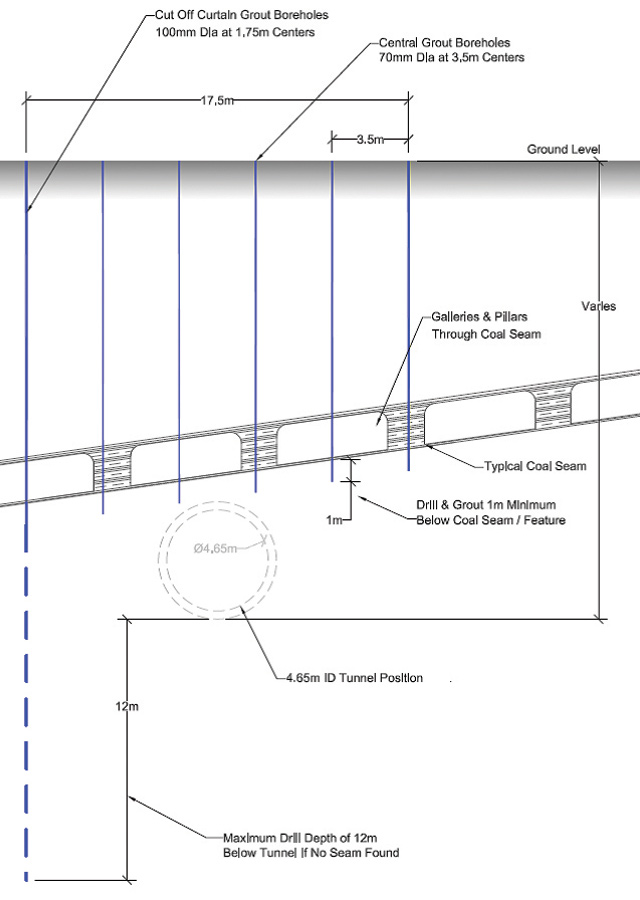
- The area has a number of old coal mine-works, some dating back hundreds of years. Old charts were consulted and geotechnical surveys and drilling rigs used to determine potential problems and deal with them.
- The coal mines treatment extent covers up to 12m below the tunnel invert within a corridor of 18m in plan. The coal seam position can vary from a few metres below the invert up to a few metres above the crown.
- The tunnel team also had to locate and, where necessary, divert other utilities that lay across the route.
Section of tunnel showing construction methods – Courtesy of Scottish Water
Cut and cover entrance to the tunnel
Soil conditions of clay and glacial tills overlaying mudstone and sandstone and the relatively shallow depth for the tunnel meant that the entrance for the TBM was a curved trench. The opening was made using a cut-and-cover method, and goes down to approximately 8-10m with a width of 6m approximately, within contiguous or secant concrete bored pile retaining walls. The construction method involved drilling/forming the piles, then excavating the first metre or so before installing temporary works, beams and hydraulic props, to withstand the lateral forces and prevent the piled walls collapsing as the excavation was dug to its final depth.
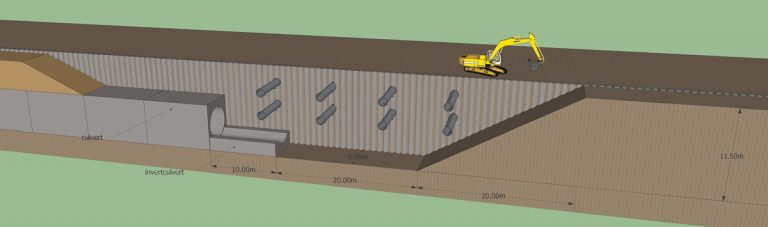
Constructing the cut and cover entrance with contiguous piling and props – Courtesy of Scottish Water
Concrete was sprayed to stem any material or water ingress into the trench and allow the cut and cover entrance to the tunnel to be installed.
The length of the cut and cover between the Shaft 1 and the start of the TBM tunnel is about 250m, long enough to allow the commissioning of the TBM in one go. The diameter of the cut and cover tunnel was modified to be the same as the bored tunnel.
The two ends of the cut and cover are used for assembling the TBM parts: the launch chamber for the shield and cutter head, and the Shaft 1 entrance is used to lower all the back-up elements (the bridge plus 11 gantries) and shift them toward the TBM head through the cut and cover tunnel.
The intention is for all the approximately 300,000 tonnes of excavated material from the TBM tunnel to be recycled, either in the Shieldhall Tunnel project itself or elsewhere.
Progress
Craigton Shaft 1: The Shaft 1 has been sunk at the Craigton site that will eventually connect the Shieldhall Tunnel with the existing Victorian-era sewer when the TBMs work is completed. This is a challenge to connect to a live sewer with 1 to 8m3/sec of flow.
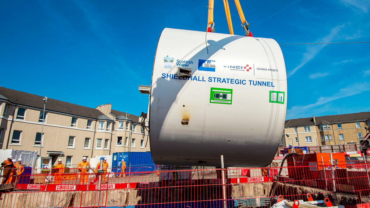
Tunnel boring machine: The slurry TBM began to arrive in sections from the manufacturers, Herrenknecht, in southern Germany. The loads came by sea to Rosyth in Fife, then overland in special convoys to the Craigton site.
In keeping with tradition, the custom-built machine has been named ‘Daisy’ by a local schoolboy. The front section was lowered into the launch chamber by crane and the subsequent sections are being lowered in Shaft 1, then shifted toward the launching chamber inside the cut and cover section as the work progresses.
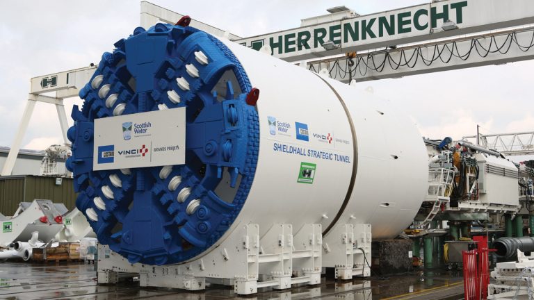
Daisy the Shieldhall TBM – Courtesy of Herrenknecht
The TBMs 5.51m cutting head will have a sealed chamber to protect tunnel workers from coming into contact with potential hazards such as old mine gas or water. The TBM has been designed specifically to treat the issue of gas. It allows collection and diversion through the slurry circuit, or evacuation through the ventilation system, of any gas that infiltrates inside the working chamber. The TBM is equipped with gas detectors to control concentration rates and adopt the necessary measures.
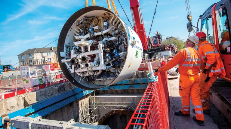
Section of TBM lowered into Shaft 1 – Courtesy of SNS
Geology
The TBM is mining in a varying geology (from very soft soil to hard and abrasive sand stone) and mixed faces with the possibility of untreated coal seams, or old mine shafts, constitute a high-level TBM mining exercise for CVJV.
The choice of slurry TBM and its data acquisition system (CAP system + Tim), allows the full control of all TBM mining parameters in real time.
Slurry treatment plant: A slurry treatment plant (STP) with a capacity of 1,200m3/h of slurry flow and a treatment capacity in line with the programmed progress rate in each type of ground is installed at Craigton main compound area.
All excavated materials are pumped from the TBM excavation chamber inside slurry pipes until reaching the STP outside the tunnel. This avoids any direct contact or possible contamination of the working space inside the tunnel with gas.
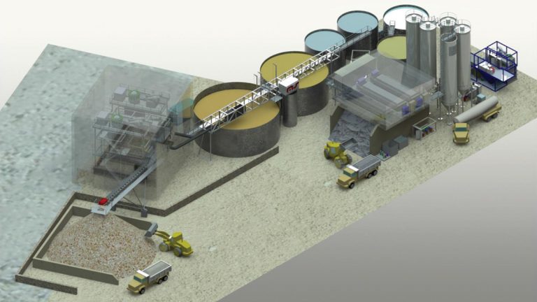
Slurry treatment plant – Courtesy of Scottish Water
The STP has been designed to deal with any presence of gas during the slurry treatment works. It has also been designed to reuse, as much as is possible, the processed water and reduce the amount of rejected bentonite. The rejected bentonite will be in form of fines mixed with the fines coming from the ground and filtered and pressed to become a solid tiles and evacuated.
Tunnel lining geometry: The tunnel lining geometry brings innovation in the methodology of tunnel lining building. The precast segments have all trapezoidal or parallelogram shapes without a small key stone. This is believed to increase the quality of ring built and the productivity.
Summary
Dominic Flanagan, senior project manager at Scottish Water, said:
“The Shieldhall Strategic Tunnel set us a number of challenges and I’m delighted the work done so far has overcome these. I wish to congratulate the team we have here on the excellent progress.”
The TBM, which weighs about 1,000 tonnes and is 180m long, was launched on 6 July 2016. The £100m project is due for completion in early 2018. The special fibre reinforcement for the concrete being used is expected to help give the tunnel a life of 100 years.