
Stoke Bardolph STW – Anaerobic Digestion (2022)
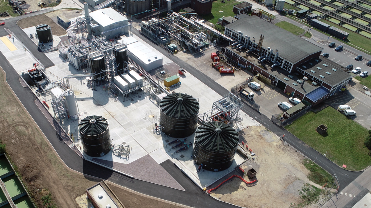
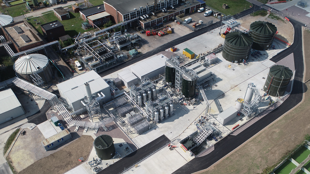
Aerial view of complete Stoke Bardolph THP Area (July 2021) - Courtesy of MMB
Stoke Bardolph Sewage Treatment Works (STW) is Severn Trent’s second largest STW and serves a population of c. 620,000. The site is also a major regional sludge centre, meaning it takes a high volume of sludge imports from other sites in the region. Stoke Bardolph has a sludge treatment capacity equivalent to a population of approximately 1.41 million. Driven by Severn Trent’s commitments to reduce its carbon footprint, the project’s outcomes were to (i) increase the sludge treatment capacity and therefore digester capacity on the existing site, (ii) maximise biogas productions from the digestion process in order to export to the domestic grid, and (iii) obtain a class ‘A’ sludge cake product. To achieve the project outcomes, a new advanced anaerobic digestion (AAD) process has been designed, constructed, and commissioned to treat a design average of 80 tonnes dry solids per day with a maximum throughput of 120 tonnes per day. This includes a thermal hydrolysis process (THP), steam raising boiler house, dewatering centrifuges, cake imports system, biogas to grid (BtG) upgrade unit and gas export main.
Location
The new advanced anaerobic digestion facility was identified to be built on a below-ground abandoned client asset. By interrogating flood and groundwater levels, the backfill height was reduced, enabling a 10,500T reduction in imported fill and reduced vehicle movements, saved 65t of embodied carbon. Material from the demolished structure was crushed and reused as backfill.
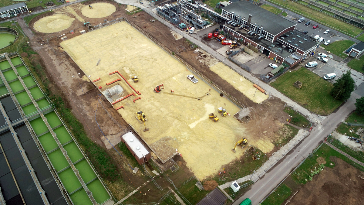
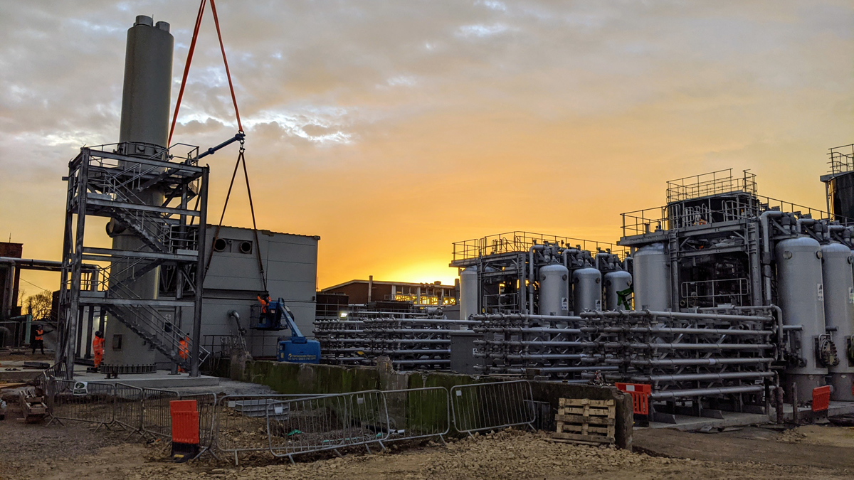
THP area site preparation (June 2021) – Courtesy of MMB
Sludge feed and primary sludge screens
Liquid imports and indigenous thickened surplus activated sludge and screened primary sludges are blended in existing sludge retention tanks on site. New sludge transfer pumps from P&M Pumps Ltd were installed to feed the new pre-thermal hydrolysis dewatering plant.
These new pumps were installed offline to prevent disruption to the digester feed throughout the construction and process commissioning period. The sludge pumps transfer the blended sludge across to the new pre-thermal hydrolysis sludge handling facility to be screened and processed. The sludge travels across site along two rising mains of 180m in length.
The sludge is screened by three Huber Technology sludge screen Strainpress 290s installed on a raised gantry to enable free discharge to the two 1,083m3 sludge buffer tanks. The design of the screens prioritised gravity discharge of the sludge to minimise potential blockages, resulting in a raised gantry and use of existing levels. Goodwin Tanks supplied the epoxy coated steel tanks. Screenings are discharged to two skips; the discharge chutes can be moved from one skip to the other without any interruption to operation.
Pre-thermal hydrolysis dewatering
The pre-thermal dewatering plant is fed by three SEEPEX UK progressive cavity pumps. The three Alfa Laval G3-115 centrifuges, in combination with the associated Northern Pump Suppliers Ltd powder polyelectrolyte plant, dewater the sludge to 20-22% dry solids. Everything was designed with careful consideration particular the access and maintenance of the pumps and centrifuge layout.
The thickened sludge is pumped to the two CTM Systems Ltd cake storage silos by three SEEPEX UK Ltd progressive cavity cake transfer pumps located beneath the centrifuges. Each cavity pump is also equipped with a boundary layer injection system to reduce pump delivery pressure.
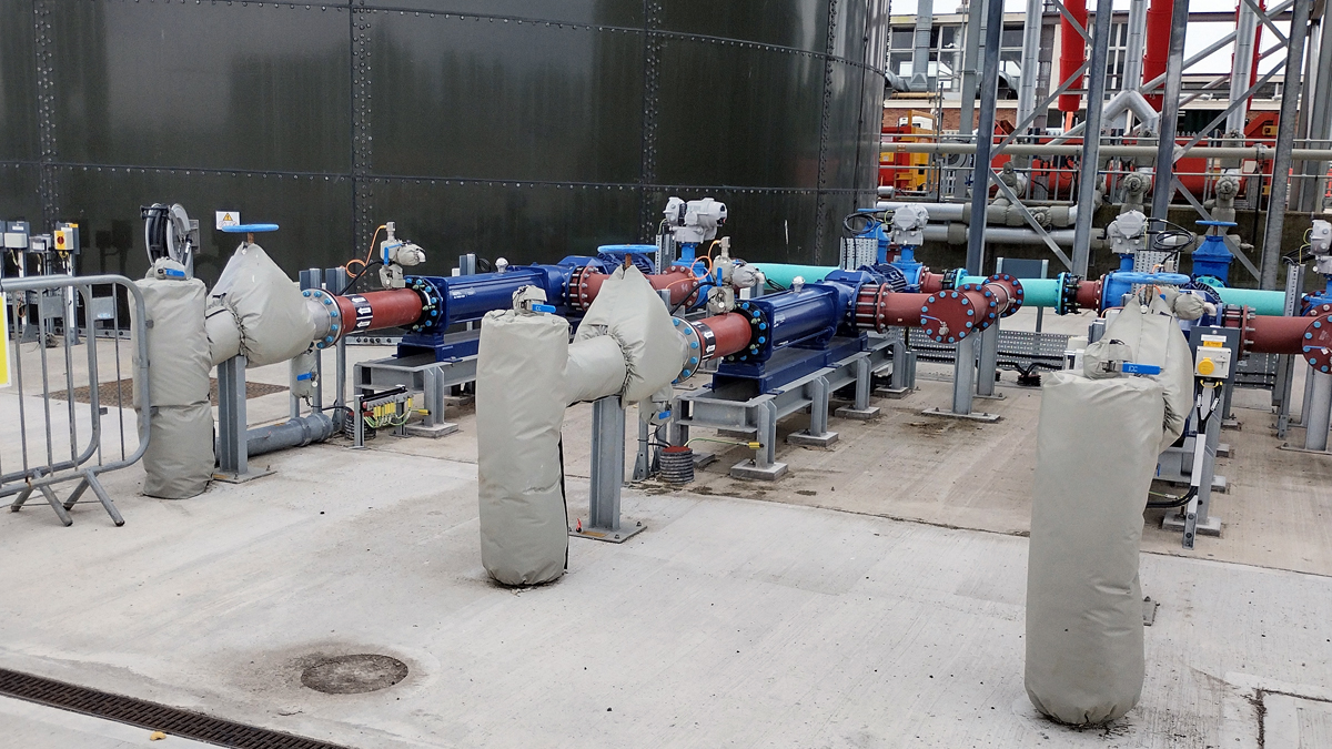
Centrifuge feed pumps – Courtesy of MMB
Cake import
The cake import bunker is designed to receive sludge cake imports from satellite sites. Vehicles each containing up to 30m3 of cake are weighed in on a new flush mounted weighbridge from Weightron Bilanciai. The cake is then off-loaded into the cake reception system where 4 (No.) shaftless screw conveyors from CTM Systems Ltd convey the cake into the hoppers of 2 (No.) SEEPEX UK Ltd progressive cavity pumps. These PC pumps combine dilution water with the sludge cake to reduce solids content to a target of 20% before pumping the sludge over a pipe bridge constructed by Alpha Plus Ltd into the cake storage silos. Boundary layer injection is again used to reduce pump delivery pressure.
The cake delivery area was deliberately designed with vehicle and process flow in mind, using an open-plan layout with minimal kerbs, easy vehicle access and safe walkways for pedestrians.
Cake storage silos
With both the site and imported sludges approaching the correct thickness for the THP process, the two routes combine in 2 (No.) glass-coated steel cake storage silos provided as part of a package solution from CTM Systems Ltd. These are situated on supporting steelwork and use a moving floor to transfer the cake to the underslung progressive cavity cake transfer pumps. These pumps are over 9m long with a screw auger section underneath the cake silo which moves the cake into the stator section of the pump. The pumps were deliberately situated off the ground to improve access for maintenance. A dilution pump provides low temperature heated final effluent (recycled from the THP process) to dilute the cake to the required 14.5%-18.5% dry solids that the THP requires. Boundary layer injection is provided on each cake pump to reduce the friction and lower pumping power.
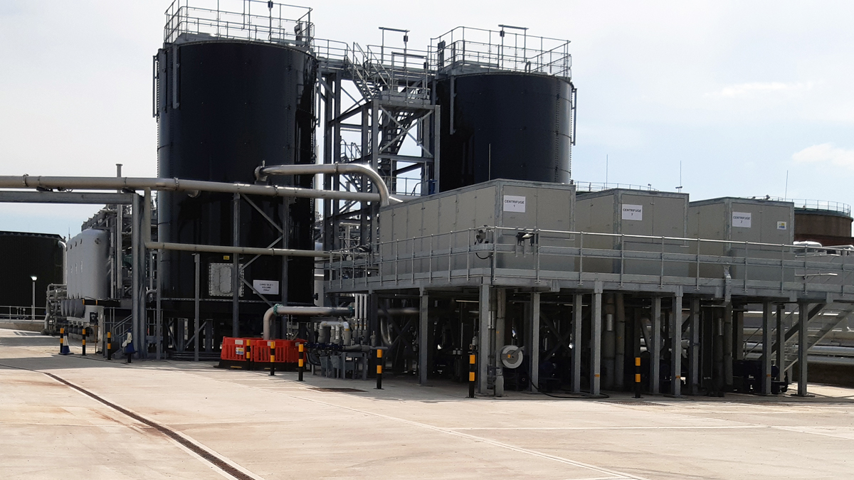
Pre-thermal hydrolysis dewatering plant with cake storage silos behind – Courtesy of MMB
Thermal hydrolysis process (THP)
There are two THP streams which are both capable of processing up to 60 tDS/day. The THP was provided by Cambi Ltd with two of their modular standard products B4. The same technology has already been proven across the UK with two other sites already in operation within Severn Trent at Minworth STW and Strongford STW, prior to this installation at Stoke Bardolph STW.
The Cambi B4 package has four reactors, one flash tank and one pulper. As part of the Cambi scope at Stoke Bardolph, they also provided the sludge distribution manifold and sludge coolers to reduce the sludge temperature to the required level before being fed in to the four existing digesters at Stoke Bardolph.
Steam raising boiler system
Steam for the THP process is produced by a duty standby dual fuel (biogas and natural gas) steam boiler package plant supplied by Dunphy Combustion. The boiler plant is capable of providing 6t of steam required for the THP from one of the boilers – the plant is designed to operate with a hot standby boiler.
The boiler house was provided as an off-site solution. This 16m x 14m x 7m building was manufactured, fully assembled and tested off-site, before being separated into modules for delivery and installation.
Conducting a full building test in the factory environment enabled the product to arrive on site in a fully tested and working condition, reducing risk to programme. Through learning, development and by challenging standards, an innovative ‘quick-fit’ electrical connection system between boiler modules was adopted; significantly reducing on site wiring. The productivity saving compared to traditional construction was 26 weeks.
The boiler plant also recovers waste heat from the exhaust gas of the existing two combined heat and power machines (CHPs) on the site to supplement the energy required for the steam required.
Boiler house install on site – Courtesy of MMB
The boiler water is fed from a potable water supply that is further treated for the specific requirements of the boiler. The boiler chemicals are dosed via solid chemical that comes in the form of small tubs, removing a key hazard at the interface of chemicals with operator.
The high-pressure steam pipework that crosses from the boiler plant to the Cambi THP Plant was manufactured and installed by Alpha Plus Ltd. The boiler house was installed in close proximity to the CHPs to minimise pipework runs and remove the need for relocation of the CHPs.
Biogas system
The Mott MacDonald Bentley design team rigorously assessed the condition and performance of existing plant to reduce unnecessary abandonment. The existing gas holder was assessed for suitability and deemed acceptable both in volume and condition for the new installation.
The biogas system upgrades therefore only required the construction of a new flare stack from Uniflare Ltd, including new flare pipework. This has a significant carbon benefit to the project removing the need to build a full new gas holding system.
Stoke Bardolph THP: Supply chain – key participants
- Main contractor: Mott MacDonald Bentley Ltd
- Design & digital twin: Mott MacDonald
- Planning consultant: Wardell Armstrong LLP
- Thermal hydrolysis plant: Cambi Ltd
- Steam raising boiler: Dunphy Combustion Ltd
- Cake reception & cake silos: CTM Systems Ltd
- Mechanical fabrication & installation: Alpha Plus Ltd
- Gas boosters & flare stacks: Uniflare Ltd
- Concrete works: Bell Formwork & Civil Engineering Services Ltd
- Boiler & operator support: EB Critical Engineering Services Ltd
- Bolted steel storage tanks: Goodwin Tanks Ltd
- Motor control centres: BGEN Ltd
- Polymer dosing plant: Northern Pump Suppliers Ltd
- Electrical installation: Main Electrical Ltd
- Odour control plant: OSIL Ltd
- GRP enclosures: Pro-tect GRP Enclosures Ltd
- UV rig: Lintott Control Systems Ltd
- Dewatering centrifuges: Alfa Laval Ltd
- Sludge screen Stainpress: Huber Technology
- Progressive cavity pumps: SEEPEX UK Ltd
- Centrifugal pumps: Sulzer Water & Wastewater
- Centrifugal pumps: Grundfos Pumps Ltd
- Chopper centrifugal pumps: P&M Pumps Ltd
- Ductile iron pipework: Electrosteel Castings (UK) Ltd
- Ductile iron pipework: Saint Gobain PAM UK Ltd
- PE pipework: Radius Systems Ltd
- Anti-foam dosing rig: Prominent Fluid Controls Ltd
- Air compressors: Atlas Copco Ltd
- Lifting equipment: T Allen Engineering Services Ltd
- Weighbridge: Weightron Bilanciai Ltd
- Steelwork fixings: Midland Fixings Ltd
- Aggregates: Total Aggregates Ltd
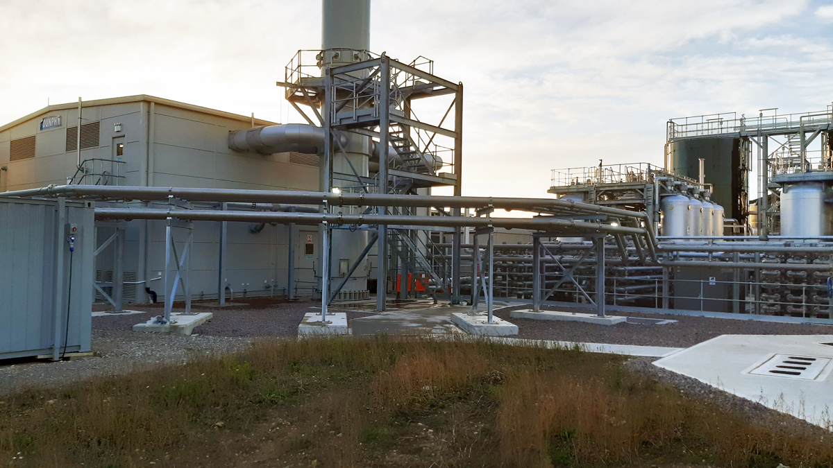
Boiler house with THP digester feed pipework – Courtesy of MMB
Digestion conversion
The existing four mesophilic anaerobic digestion (MAD) digesters were assessed for their practical use as THP sludge digesters. Key considerations were sludge density differences and changes, working levels and overflows, gas pressure and production increase, suitable instrumentation and controls including DSEAR interlocks, and feed and recirculation configuration.
Modifications were made to meet these considerations without the need to drain a digester.
Motor control centre and site-wide electrical install
The main THP area was powered and controlled by on main motor control centre (MCC), with a separate MCC for the digester modifications and the washwater upgrades.
These MCCs were all provided by BGEN Ltd houses in GRP kiosks provided by Pro-Tect GRP Enclosures Ltd. The main THP MCCs needed to house a significant number of drives and controls for the new plant and integrated the Cambi supplied MCC as well.
Early design discussions and collaboration with the construction delivery team identified opportunities to significantly improve the construction environment. One example was provision of better access for the significant cabling across the new plant.
This was achieved by:
- Improved access to the bottom entry motor control centre trench by increasing the height. Normal practice is a 1.1m deep trench. An easy design change enabled a height increase to provide standing working height within the cable area, massively improving access for the installation team. To further improve the working environment permanent access stairs were provided instead of temporary.
- Design decisions to ensure the draw pits throughout the site and size of cable ducts were adequately sized for easy access for cable pulling. This was achieved by using a main corridor of cable ducts with larger diameter ducts, straight runs and a sufficient amount of them to make pulling of long lengths of cabling more manageable.
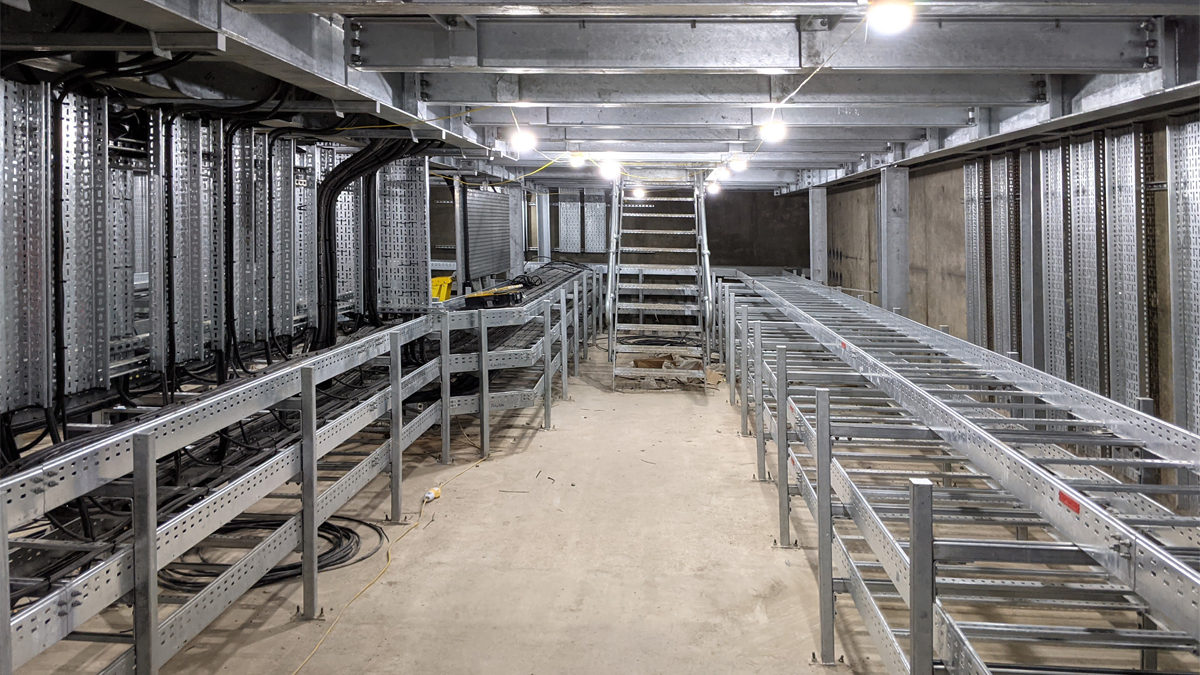
Motor control centre trench – provision of access to improve construction environment – Courtesy of MMB
Digital twin
An innovative digital twin was constructed for this project by Mott MacDonald Bentley (using their Mott MacDonald MOATA system) to model the THP and the digesters. The new THP process creates a substantially different biological environment within the digesters, resulting in the need for a careful transition from MAD to THP.
This was an industry first for a United Kingdom THP project with daily plant readings and results from physical samples being inputted into the model for calibration prior to the conversion.
Washwater upgrades
To meet the new demands of the sludge treatment process, the existing site final effluent washwater system needed a significant upgrade.
As part of the works, two new submersible transfer pumps from Sulzer Pumps Wastewater UK ltd were installed to feed both an existing buffer tank and a new buffer tank. A full new network was installed to feed the new THP area of the site with dedicated Grundfos booster pumps.
To prevent contaminants being introduced via untreated washwater post-THP, an ultraviolet (UV) treatment rig from Lintott Control Systems was constructed along with its own site-wide network. The solution for the UV treatment rig was delivered as a full off-site factory built assembly.
Safety – “My Space” campaign
This MMB initiative aimed to promote and maintain the highest standard of housekeeping and cleanliness across the site. This was achieved by giving clear ownership to individuals for specific areas on site and welfare units. Empowering them to manage material storage, waste management and access.
Drawings/aerial photos were annotated and displayed to ensure visibility of the individual areas to all persons engaged on the project, this formed part of the site induction process. This led to empowering the multitude of subcontractors delivering elements of DfMA on site to take a responsibility in the quality of their work and the way they managed their working area.
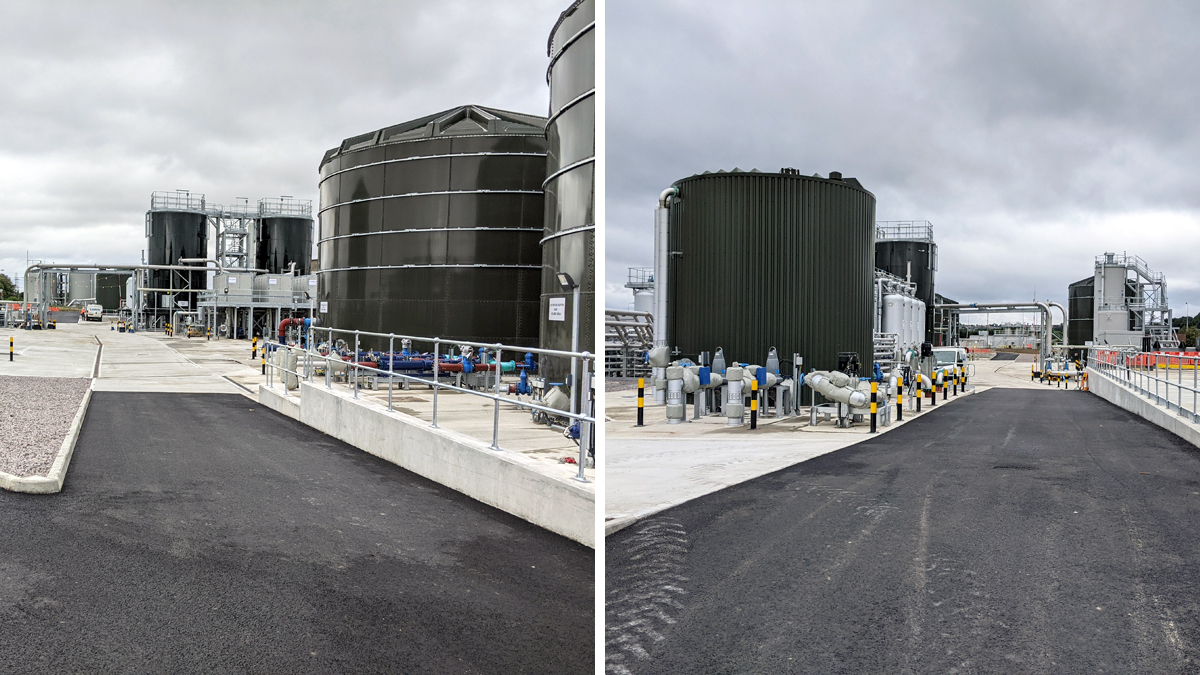
Entry and exit roads to and from the THP area – Courtesy of MMB
The “My Space” campaign compliments the great reporting culture at MMB. Over 3300 positive interventions have been reported and despite over 200,000 hours worked, the project was delivered to a world-class safety standard without any LTI/MT/RIDDOR/Environmental incidents. Audited frequently throughout the delivery, the project achieved 93% in client audits, highlighting the highest standards.
Summary
The Stoke Bardolph THP project went from breaking ground on site in January 2019, within significant construction complete by July 2021, final commissioning was complete two and a half years after the project start. The project is projected to finish in gain.
Delivering greater capacity for the site, higher quality sludge cake and a renewable source of gas for the local community, the project has been a great success. Leaving a great legacy at Stoke Bardolph Sewage Treatment works for years to come.
Aerial view of the completed THP area – Courtesy of MMB
What they said:
Michael Fairlamb, Severn Trent Regional Manager, Capital & Commercial Services
“The project has been very successfully delivered for the benefit of the environment and our customers. This is particularly pleasing because of the constraints and unknowns that faced us all as a result of the pandemic. People and materials had to be brought in from mainland Europe and beyond and the lockdowns made this all the more of a challenge. Careful design and the use of BIM, including digital twins, helped to ensure that the site layout was optimised, and interfaces carefully managed before installation of the plant commenced. This reduced construction and installation timescales and improved our health and safety performance. Collaboration and courage throughout the team has been instrumental in achieving a sustainable, lasting legacy for which the team are, quite rightly, very proud.”
Colton Cropper, Severn Trent Bioresources Operations Team Manager
“A textbook example of quality collaboration. Bringing together multiple factions and ensuring all our experience is shared creating a safer better faster scheme delivered to the highest standard. The quality of the delivery of this project is second to none, there has been industry leading learnings taken from multiple different prior projects and implemented. This provides a huge level of resilience and future-proofs Severn Trent’s second largest sludge treatment facility.”
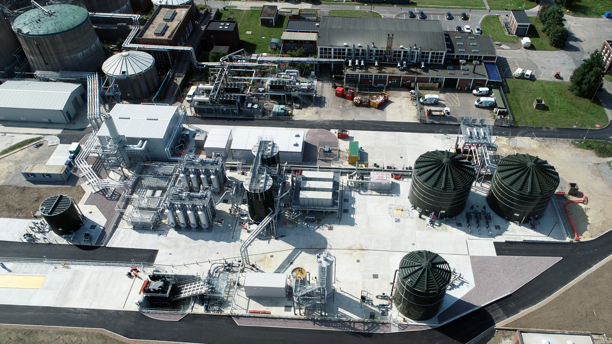
Aerial view of the completed THP area - Courtesy of MMB