
Swinsty Impounding Reservoir (2022)
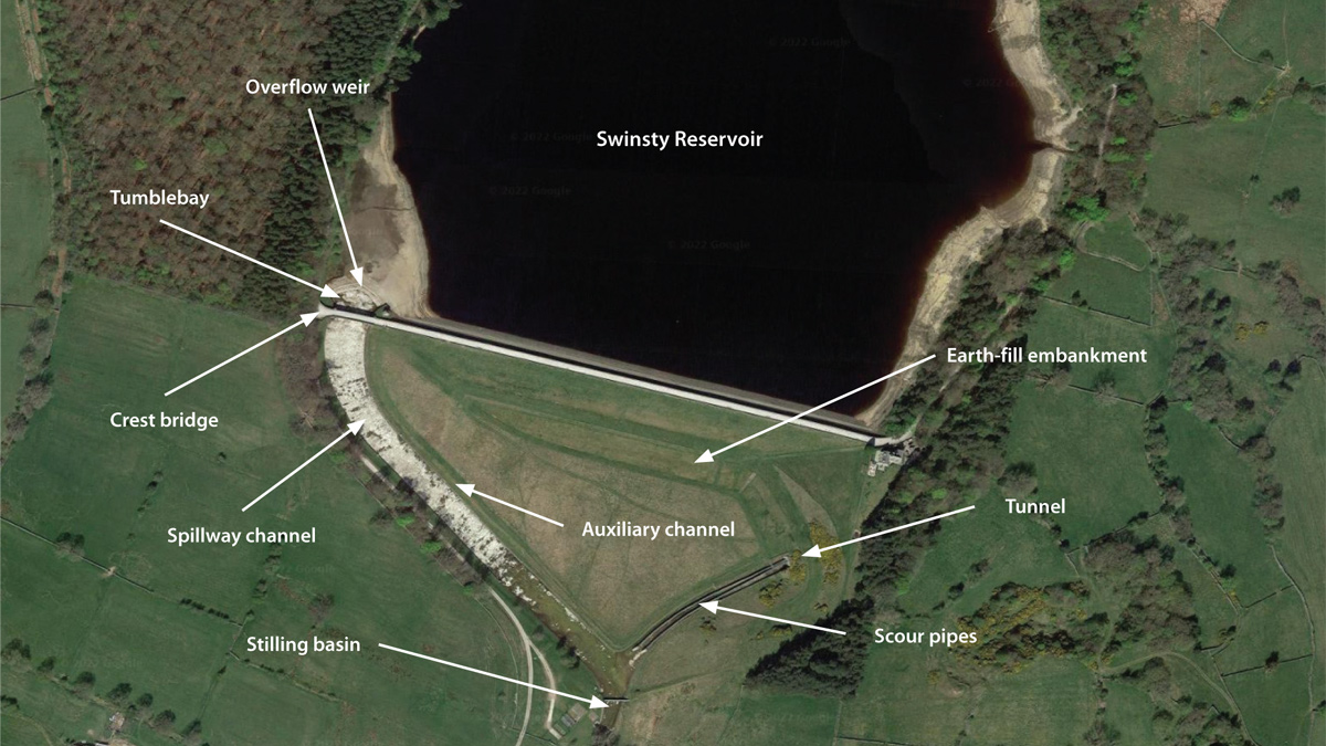
Google Maps image of Swinsty IRE - Courtesy of MMB
Swinsty Reservoir is the third in a cascade of four impounding reservoirs in the Washburn Valley, North Yorkshire. The reservoir is impounded by a 490m long, 24m high earth-fill embankment dam with a central puddle clay core, storing 3.94 million cubic metres at top water level. The overflow is located on the right-hand side (RHS) of the dam, consisting of an overflow weir, tumblebay and masonry lined spillway channel (see above). Swinsty Reservoir is owned and operated by Yorkshire Water. It is a very popular recreational site, with a circular walking route around the reservoir. A single span road bridge connects the embankment crest to the track on the RHS of the reservoir and crosses over the spillway channel.
Investigation works
The Reservoirs Act 1975 requires inspecting engineers to carry out safety inspections every 10 years (Section 10 Inspections) of reservoirs with storage volumes greater than 25,000m3 to ensure reservoir safety. A Section 10 Inspection took place at Swinsty Reservoir in July 2016. The recommendations in the interest of safety were to carry out a flood study, investigate the stability and integrity of the spillway channel and produce an engineering solution if required.
Yorkshire Water, the reservoir operator and owner, contracted Mott MacDonald Bentley (MMB) to carry out the recommended investigation works in 2017 and Stantec UK produced the concept design during the tender phase of the project in 2020. The investigation concluded that the spillway crest bridge restricted flow into the spillway and the existing spillway channel was under capacity and not structurally adequate.
It was recommended that the spillway crest bridge was permanently raised by 775mm, and a new concrete lined spillway, clad in masonry, installed to safely pass the predicted maximum flow (PMF) event to prevent water escaping the spillway channel and causing potential erosion of the embankment.
Swinsty Reservoir Safety Improvement Works: Supply chain – key participants
- Client: Yorkshire Water
- Outline design: Stantec UK
- Detailed design & principal contractor: Mott MacDonald Bentley
- Bridge specialists: Mott MacDonald
- Concrete works: Offafix Formwork Ltd
- Masonry cladding: Colin Richards
- Bridge jacking: Mabey Hire
Design
Remote Working: The detailed design phase of the project began in June 2020, during the Covid-19 pandemic, therefore each project team member was working from home so new ways of working had to be quickly adapted to keep the collaboration and teamwork between different parties going to successfully deliver the scheme.
The project used Miro, an online collaboration platform, to carry out a Construction Lean Improvement Programme (CLIP) session at the start of the project as it offered great collaboration whilst working remotely. It was very visual and easy to update when compared to using Excel.
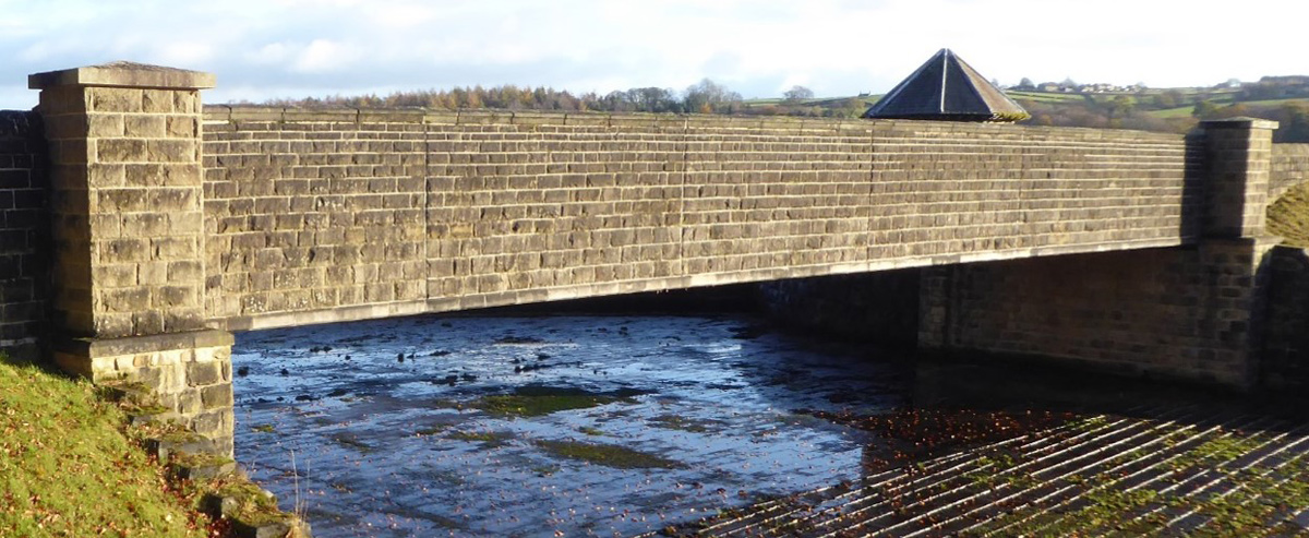
The existing bridge before the bridge raising works – Courtesy of MMB
Planning Application: The first stage of the project was to produce the planning application, which is required in the UK to ensure that developments are sustainable. Developments must be aligned with both the National Planning Policy Framework (NPPF) and Local Plans and Core strategies. Core planning principles within the framework include the need to:
“… contribute to protecting and enhancing our natural, built and historic environment; including making effective use of land, helping to improve biodiversity, using natural resources prudently, minimising waste and pollution, and mitigating and adapting to climate change, including moving to a low carbon economy”.
There were three specialist reports produced to demonstrate the development at Swinsty aligned with these principles. This included a Heritage Statement, Landscape and Visual Impact Assessment and a Preliminary Ecological Appraisal (PEA). Specialist input from across the wider Mott MacDonald group was brought in to produce these reports, to ensure technical excellence.
The Heritage Statement assessed Swinsty Reservoir as being an asset of local heritage significance. Existing structures and assets have therefore been utilised as much as practicable to retain heritage. For example, the existing bridge has been raised rather than replaced, the original spillway coping stones have been re-used for the new spillway walls and the original channel forms the foundation for the new spillway. Utilising existing assets has reduced the amount of imported materials required, improving sustainability whilst also protecting the historic environment. The new concrete spillway was also required to be clad in masonry to stay in-keeping with the local environment.
Planning permission was received in early 2021.
Spillway Detailed Design: The spillway channel was design as a reinforced concrete structure with wall heights taller than the original channel to contain the PMF event. The PMF storm event had to be modelled through computational fluid dynamics (CFD) to determine the required wall heights of the new spillway structure to fully contain the water. The new spillway channel was modelled inside the existing channel to reduce the amount of demolition works required.
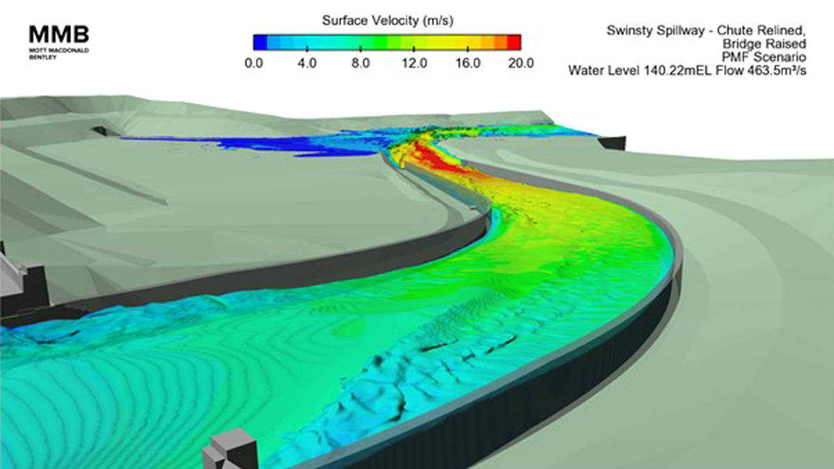
CFD model of the proposed solution for the spillway channel under a PMF event – Courtesy of MMB
Global Stability: The new spillway channel had varying wall heights around 4.5m in height, which were to be clad in masonry. The channel was to be built within the existing spillway channel which only had wall heights of less than 1.5m, therefore the new walls were significantly higher than the existing channel.
Calculations for flotation, bearing, sliding and overturning using Eurocodes were carried out to ensure global stability of the new structure.
With the new structure set into the ground, back of wall drainage was used to control ground water levels and therefore the uplift pressures on the structure to ensure structural stability. The drainage was set on top of the existing wall and then installed through the new backfill up to the new, higher, ground level. Large dowels were also installed between the new structure and the existing structure to bond together the masses to create extra resistance against uplift. The risk of overturning was low due to the symmetrical nature of the layout, but sliding checks were carried out on the channel to ensure it did not slide down the gradient of the spillway.
The planning authority had stipulated that masonry cladding would be required due to how visible the spillway was from popular public footpaths. The spillway cross section was designed to have a 100mm step in the back face of the concrete to act as a support ledge for the top 1.1m of masonry cladding and also to allow the existing coping stones to be re-used whilst maintaining a slight overhang past the masonry cladding. On the inside face of the concrete cladding rails were cast vertically into the concrete to allow for masonry ties to be installed between the courses of masonry.
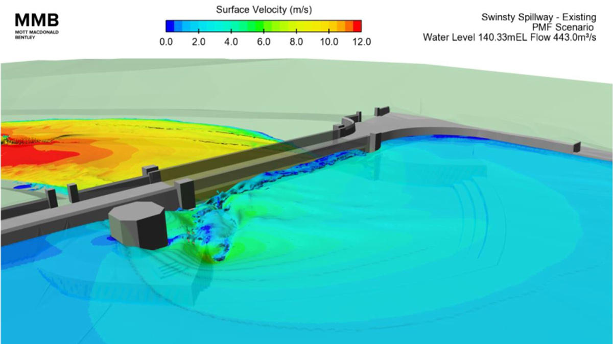
Extract from the CFD model showing the bridge causing a restriction in flow – Courtesy of MMB
Bridge Raising Works: In the early design phase of the project the CFD model showed that the existing spillway bridge was causing a restriction in the PMF event. This was causing the water in the reservoir to rise to un-safe levels and could cause structural instability of the bridge. The decision was taken to permanently raise the bridge by 775mm to prevent this from occurring.
The existing bridge was surveyed and design drawings produced. Bridge specialists from across the Mott MacDonald group were brought in to design the required plinth raising and ballast wall raising works. Global stability checks were carried out on the full abutment walls for the increase in loads and individual raised elements were designed and detailed. New approach ramps were also designed to tie the new higher level bridge design back into the existing crest road level.
Construction Phase
Work began on site in November 2020 with the enabling works which included access road improvement works and public footpath diversions. Diversion routes had to be created and formed around the working area as the popular public footpath across the crest road of the embankment had to be closed during the full duration of the works. An access road was installed down the mitre of the embankment and a compound and material storage area created on the flat ground at the toe of the embankment.
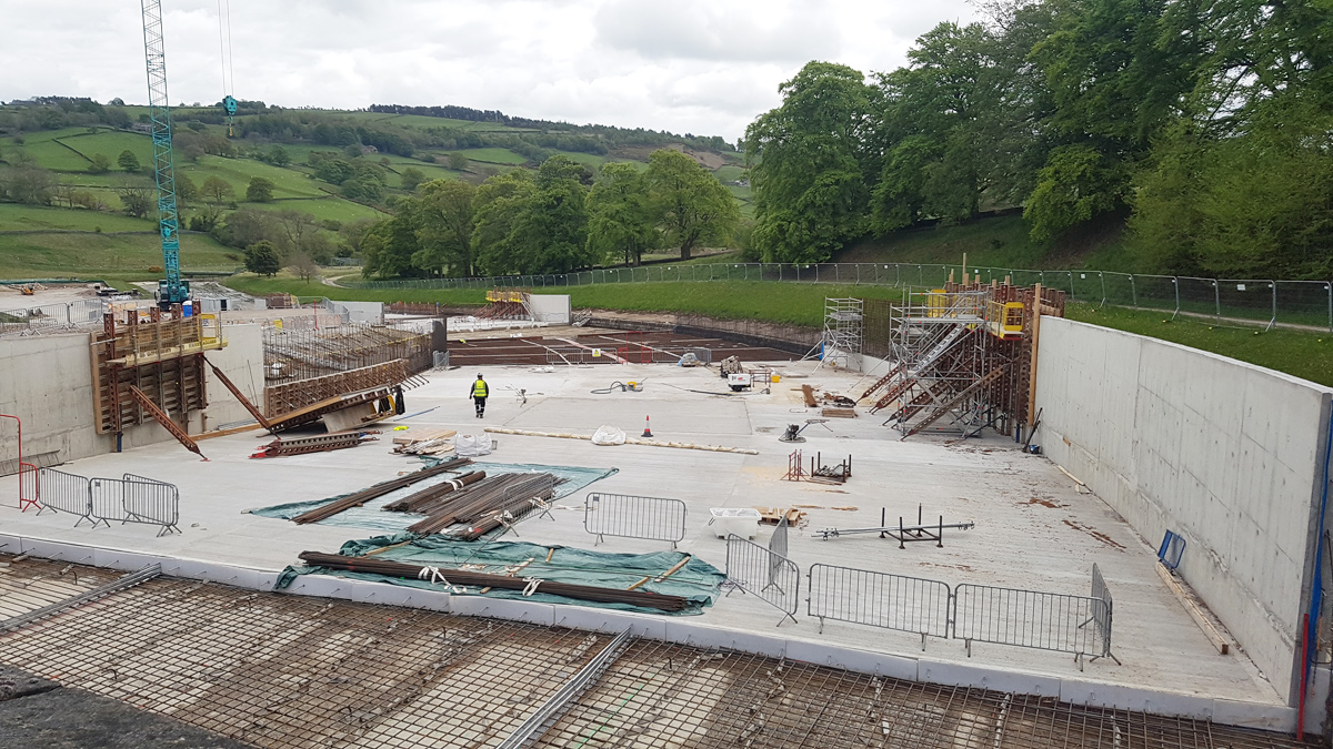
Construction works in the spillway showing the new channel – Courtesy of MMB
Works began to construct the new spillway in March 2021. The new spillway was approximately 25m wide by 250m long and the concrete pour sequence was broken down into smaller bays suitable in area for the amount of concrete that could be delivered and placed in a working day. Concrete pour bays were staggered to allow time for the place concrete to cure and shrink before adjacent bays were poured. Two large crawler cranes serviced the works from the embankment side and steel fixers were always ahead of the concrete works to ensure programme was maintained.
Following completion of the concrete channel, the masonry cladding was installed on all exposed concrete walls and the ground levels backfilled on the exterior of the channel.
The bridge raising works required the existing bridge to be jacked up by over 1.5m to allow enough working room to undertake the permanent raising works to the bearing plinth and the ballast wall.
The operation and maintenance manuals for the existing bridge stated that it was “designed to be jacked”. There were jacking stiffeners on the first cross beam, but the jacking sub-contractor highlighted that they would need to jack and prop between two beams. This was because the hydraulic jacks could only lift the bridge around 200mm at a time. Additional jacking stiffeners were therefore designed and installed on the second cross beam of the bridge.
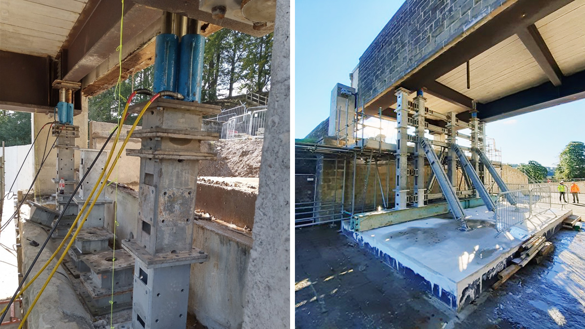
(left) Bridge being raised on the jacks and (right) bridge on its props in the final temporary position – Courtesy of MMB
Once the bridge was raised up to its final temporary position, works began to hydro-demolition out part of the existing bearing plinths and ballast walls. This was to expose existing reinforcement to ensure new reinforcement could be installed and tied into the existing structure.
Once the works to raise the bearing plinths and ballast walls were complete the bridge was lowered backed down onto the bearings and the new approach walls and ramps to the bridge were constructed.
Conclusion
The construction works are now complete, and the site was demobilised in April 2022 after successful completion of the scheme. Both the client, Yorkshire Water and the QCE overseeing the project commented on the quality of the work and the success of the finished scheme in delivering the desired outcoming of improving the performance of the spillway to ensure reservoir safety.
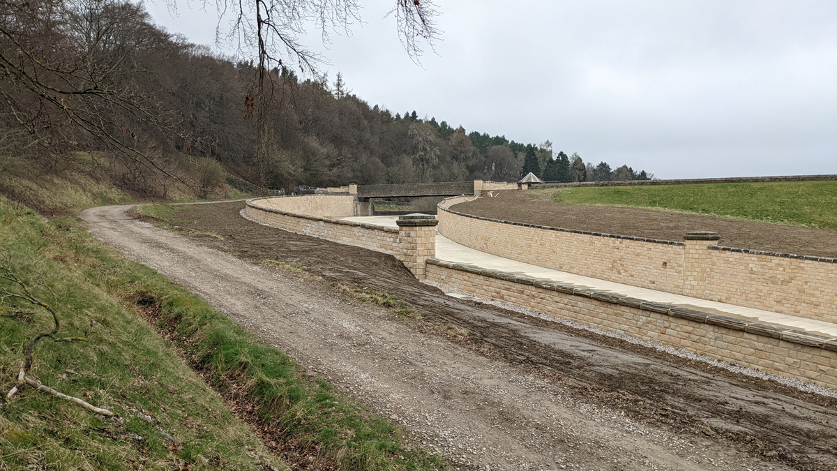
Final complete spillway and bridge raising works – Courtesy of MMB
Following a post project review the main successes were in using 3D modelling to aid both design and construction, the re-use of materials on site and the early involvement of sub-contractors into the design process.