Te-Tech Process Solutions
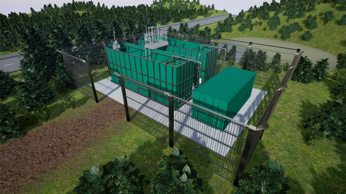
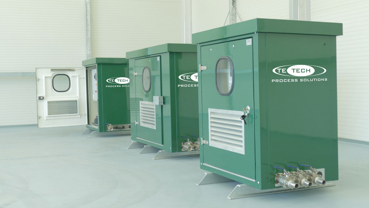
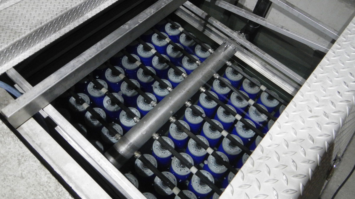
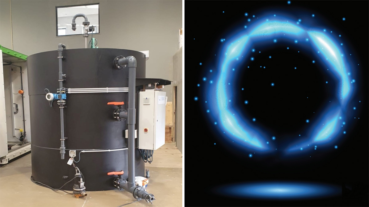
te-cyc™ (2021)
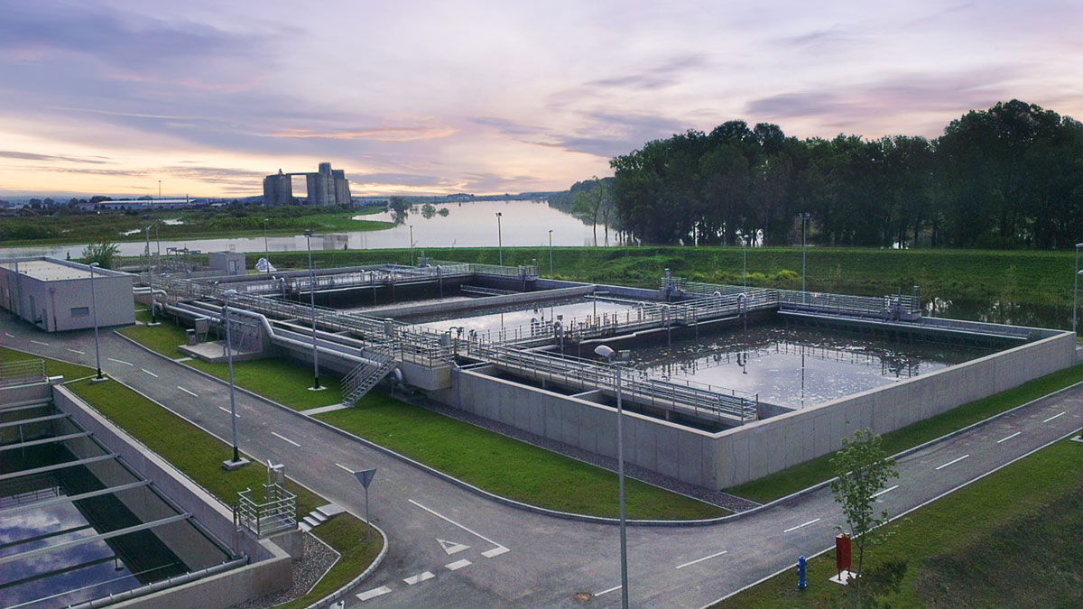
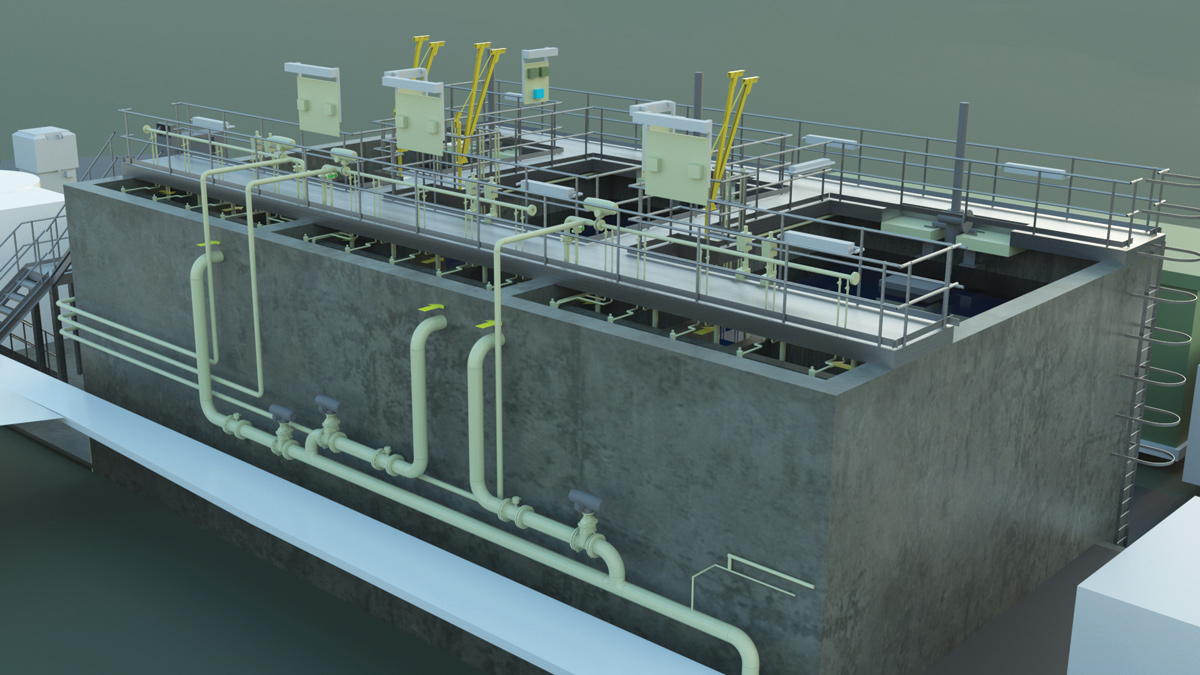
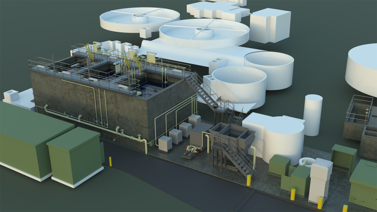
te-cyc™ modular treatment plant - Courtesy of Te-Tech Process Solutions
The Water Industry National Environment Programme is now well integrated into Water Company business plans and the process changes needed to meet tightening discharge consents, particularly in relation to phosphorus removal, are already being implemented in AMP7 capital delivery programmes. For many smaller works, enhancing phosphorus removal involves an increase in chemical dosing to precipitate phosphate in the sludge. This appears, at first sight, to be a low cost option because the capital costs of chemical storage, dosing plant, and tertiary filtration equipment are usually lower than those of alternative processes. But these installations also create a long-term operational cost legacy together with the issues associated with the handling and storage of chemicals and disposal of chemical sludges, particularly on unmanned, rural, or remote sites. Te-Tech Process Solutions, working with their strategic partner SFC Umwelttechnik, are offering advanced cyclic activated sludge technology, te-cyc™, as a more cost-effective long-term sustainable solution to satisfy tightening discharge consents and growth drivers through a range of bespoke and off-site manufactured package treatment solutions.
The te-cyc™ process
The process is an enhanced sequencing batch reactor (SBR), where secondary biological treatment and tertiary settling are combined in a single tank. The te-cyc is configured with two or more batch tanks installed in parallel with their sequences out of phase with each other allowing for a continuous flow through the system. Therefore, the te-cyc can be regarded as a cyclic activated sludge process.
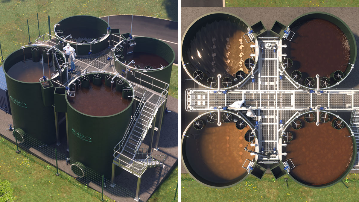
Unlike traditional SBR systems, no upstream buffer tank is required for the system, which ultimately reduces the overall site footprint by approximately 50% compared to conventional continuous flow technologies. The unique features of te-cyc include simultaneous nitrification/denitrification during the aeration phase and the mandatory selector zone for biomass conditioning which distinguish the process from other traditional SBR type processes. The cyclic activated sludge process consists of several circular or rectangular batch reactor basins each containing an anaerobic selector zone, aeration zone, internal recycle and decant arm. An optional oxygen uptake rate (OUR) based aeration process control system is also available to optimise aeration and can give significant energy savings.
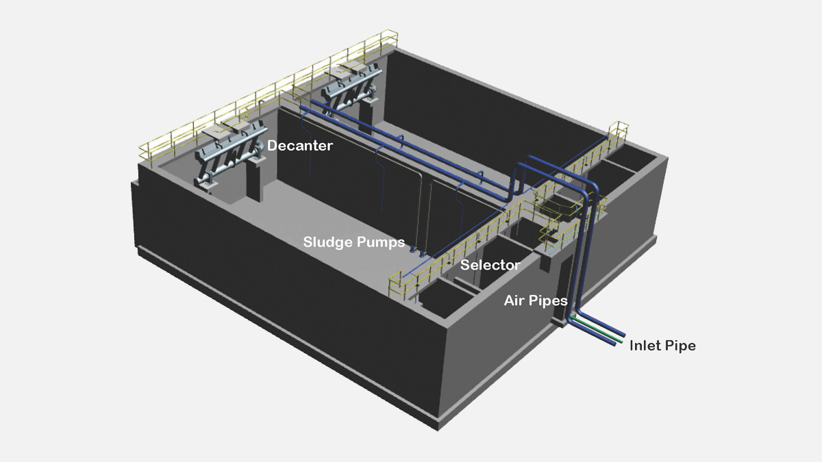
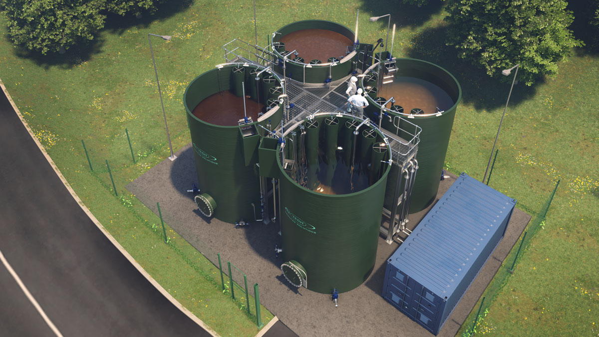
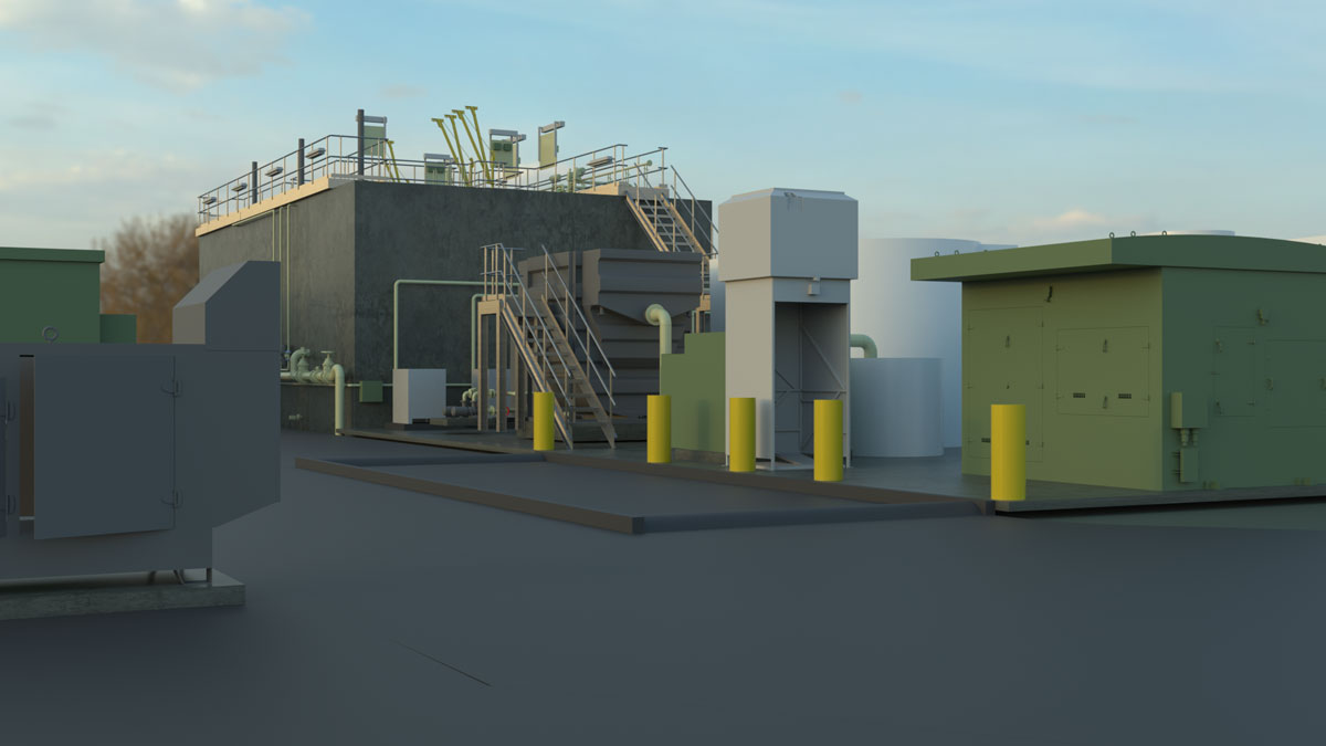
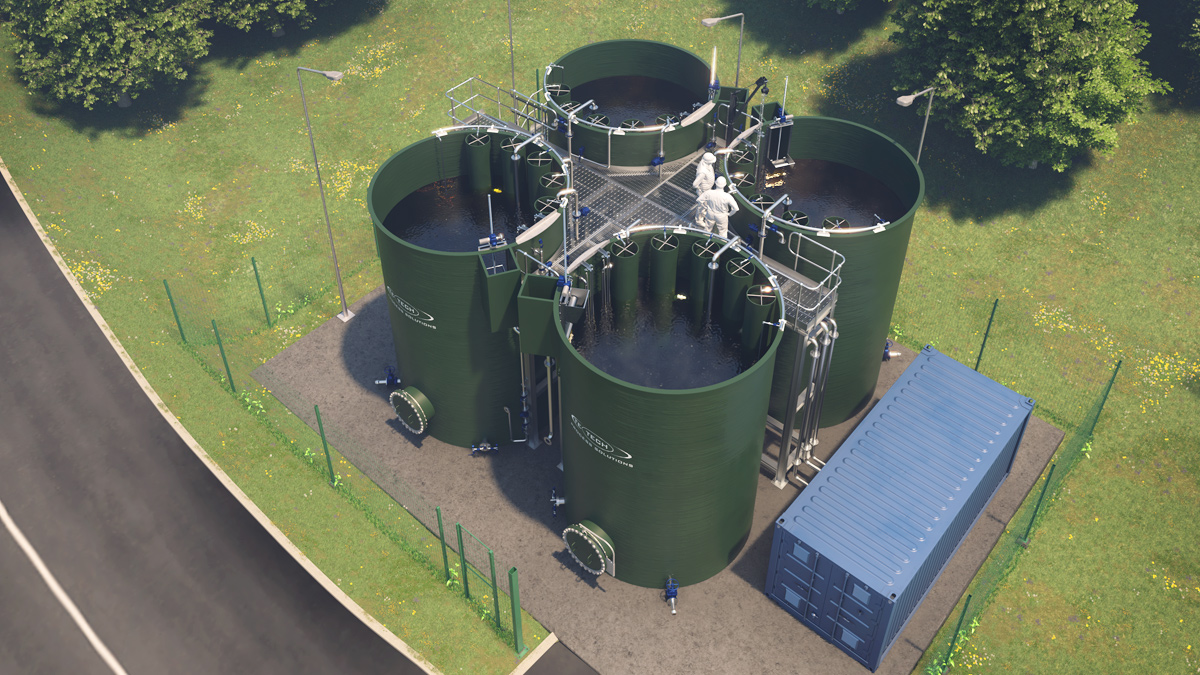
Figure 1: Typical te-cyc™ arrangement – Courtesy of Te-Tech Process Solutions
Cyclic process
The process is broken down into three distinct stages that operate on a cycle in a sequence: fill/aerate, settle, and decant.
During the fill/aerate stage water enters a single te-cyc basin into the aerated zone via the anaerobic selector. Throughout this fill stage, the aeration zone is continually aerated at a controlled rate and a portion of the sludge is constantly recycled to the inlet of the selector. The design of this selector and recycle rate allows for the formation of macroflocs in which simultaneous nitrification/denitrification, BOD5 removal and biological phosphorus removal occurs. Moreover non-floc formers and filamentous microorganisms are suppressed to the best possible extent by natural selection mechanisms.
During the settling phase, the inlet to the particular basin is closed, the internal recycle is stopped, and the sludge formed in the previous stage aggregates as a blanket and settles to the base of the reactor tank leaving a top layer of clear treated effluent. In typical wastewater applications, the settled sludge layer has a mean biomass concentration of around 10 g/l and operational sludge volume indices (SVI) of typically 60-100 ml/g.
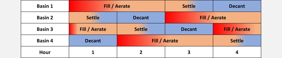
Figure 2: Typical cycle sequence and times for a four basin te-cyc™ plant – Courtesy of Te-Tech Process Solutions
In the decant phase, the mechanically driven decanter moves from the top water level to the bottom water level to remove approximately one third of the reactor volume which will be clear treated effluent. The decant arm also features all-side scum guards which prevent floating solids from discharging into the decanter. At the end of the decant phase, the decant arm is returned to its parking position. Towards the end of the decant phase, a portion of the settled surplus sludge at the base of the reactor basin is discharged. The rate at which the decanter is lowered and, hence, the rate of treated wastewater discharge, can be varied during the decant phase.
This cycle is typically four hours for dry weather flow and is repeated continuously as shown in Fig 2 and Fig 3. Having multiple reactor basins in parallel, with their cycles out of phase with each other, means that the total system can handle continuous flow without the need for an upstream buffer tank.
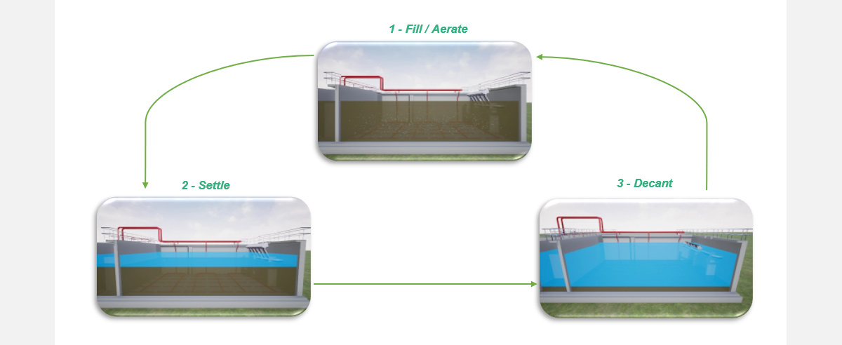
Figure 3: te-cyc™ process cycle – Courtesy of Te-Tech Process Solutions
The flow and aeration control systems are designed with dry weather flow and wet weather flow operating protocols as standard, with maintenance cycles available with three or more parallel reactor basins. The transition between cycles, whether automatic or manual, is done via the PLC system without affecting the continuity of the plant operation.
Oxygen uptake rate (OUR) control
The OUR control system is particularly applicable to biological nutrient removal. It uses only a measurement of the dissolved oxygen within a reactor basin to determine the actual oxygen uptake rate of the biomass available. In doing so, the required duration of aeration within the fill/aerate cycle and the rate of aeration to achieve complete nitrification and BOD/COD removal is calculated and implemented. Employing the control system prevents over-aeration of the reactor basin and creates energy savings. Several operational te-cyc plants of varying capacities between 9,500 and 109,800 PE were investigated to quantify the required energy difference between plants using OUR control and plants using a constant DO set-point.
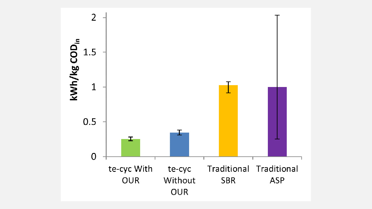
Figure 4: te-cyc™ energy usage for plants with and without OUR aeration control compared to traditional ASP and SBR processes. kWh/kg CODin calculated assuming 0.12 kg CODin / PE.d – Courtesy of Te-Tech Process Solutions
Figure 4 shows the energy required per kg COD entering the process for plants with and without OUR control as well as how these compare to the energy required for traditional ASP and SBR processes as found in published data Enerwater 20151 (note: the figure refers to a statistical evaluation of data and does not necessarily reflect the circumstances in an individual case). On average the energy required for plants using OUR control is 27% less than those without, and compared to traditional ASP and SBR processes, the energy requirement of the process is on average around 70% less.
Macrofloc formation
The anaerobic selector zone and internal recycle of the te-cyc system allows for the formation of so called ‘macroflocs’ in which extracellular polymeric substances (EPS) produced by the floc forming microorganisms under stress conditions act as a ‘glue’ between the microorganisms. These floc formers show a selection advantage over other non-floc formers because they are able to rapidly sequester the soluble COD in the raw wastewater as intracellular carbon source storage. This stored carbon, captured in the selector zone, will be utilised as an additional carbon source for denitrification in the internal anoxic/anaerobic zone of the macrofloc. Here, nitrate is converted to elementary nitrogen, diffuses out of the macrofloc and dissipates into the atmosphere.
The enhanced size of these macroflocs means that each floc contains an external aerobic zone and an internal anoxic/anaerobic zone even during the aeration phase of the process cycle. This means that both nitrification and denitrification occur simultaneously within the same reactor zone and cycle phase, reducing both the required reactor volume and overall cycle time when compared to traditional ASP or SBR processes. It also eliminates the need for mixers in the would-be anoxic zone/phase. A representation of this simultaneous nitrification/denitrification within the macroflocs is shown in Figure 5.
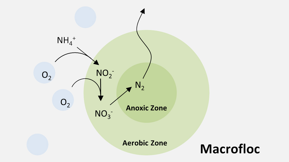
Figure 5: Macrofloc nitrification and denitrification pathways – Courtesy of Te-Tech Process Solutions
Enhanced biological phosphorus removal
The anaerobic selector zone provides the perfect conditions for the growth of polyphosphate accumulating organisms (PAOs) within the macroflocs. The mechanism for removal begins with the PAOs releasing all of the polyphosphates contained within them in the selector zone and then uptaking a greater amount of phosphate from the surrounding bulk liquor within the aerated zone. This is the so called luxury uptake cycle for enhanced biological phosphorus removal. The phosphate-rich organisms are then periodically removed with the settled sludge during the period of sludge wasting in the decant phase.
Under favourable conditions the te-cyc can provide treated effluent phosphorus concentrations of less than 1 mg/l P without the need for chemical dosing. For more stringent phosphorus limit, chemical dosing, such as ferric chloride, will still be required. Typically, 0.3 mg/l P is achievable without tertiary filtration and 0.1 mg/l P with the addition of a tertiary filter. In both cases, the amount of chemical required will be significantly less than that required in a conventional ASP or traditional SBR, as biological phosphorus removal is maximised in the te-cyc process.
Hawkhurst WwTW Southern Water UK 2,285 PE – Courtesy of Te-Tech Process Solutions
The predicted performance of phosphorus removal is site specific, being dependent upon the availability of volatile fatty acids (VFA) as nutrient for the PAOs. As a result, chemical dosing should always be considered where high phosphorus removal rates are required.
A solution for small works
The te-cyc process is well established with over 600 reference plants with capacities up to 1.2 million population equivalents, treating a wide variety of wastewater types in a range of climatic conditions, but Te-Tech Process Solutions has developed a range of standard packaged plants, that bring the benefits of biological phosphorus removal to small to medium sized works. Minimal chemical dosing means fewer transport movements, less chemical sludge for disposal and a lower environmental impact with concomitant cost savings. Effective solids removal without the need for tertiary filtration means a smaller footprint and lower maintenance. Biological phosphorus removal together with simultaneous nitrification and denitrification meets the tightening nutrient consents in a sustainable and resilient way.
The packaged plants are designed in-house and manufactured and assembled off-site, which allows better quality management, factory testing and acceptance and reductions in installation time on-site and the associated risks.
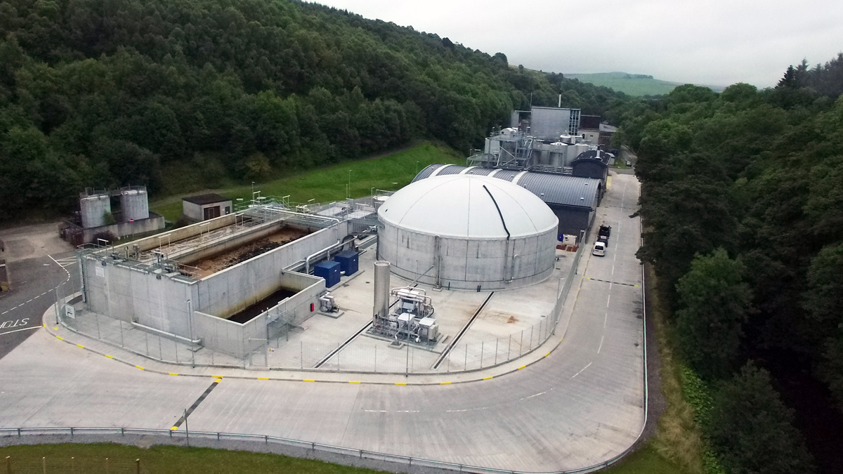
Glendullan Distillery WwTP UK 20,663 PE – Courtesy of SFC Umwelttechnik
Summary
The te-cyc process is an established solution with over 600 installations in a range of applications to meet tightening discharge consents and growth drivers. Reference plants demonstrate the versatility of the process which, in addition to enhanced biological phosphorus removal, can be adapted to achieve: best possible nutrient removal, low temperature nitrification and simultaneous sludge stabilisation. The development of a standard off-site manufactured package solution is ideally suited to provide a long term sustainable solution for small treatment works.
References: 1 https://www.enerwater.eu/wp-content/uploads/2015/10/ENERWATER_D2.1-Study-of-published-energy-data-Will-contain-data-of-at-least-500-WWTPs.pdf
This paper was prepared by Ben Hazard and Michael Froom of Te-Tech Process Solutions Ltd, UK, and Dr Simon Jabornig and Dr Konrad Wutscher of SFC Umwelttechnik GmbH, Austria.
For more information: Te-Tech Process Solutions Ltd | +44 (0)2382 351600 | www.te-tech.co.uk