
Tideway East – Hydraulic Modelling (2019)
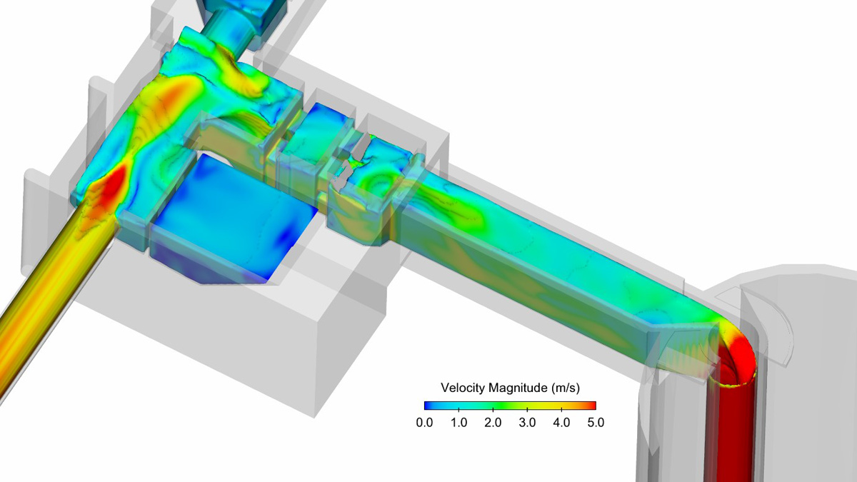
CFD Modelling: View of Earl Pumping Station interception structures and approach to vortex drop shaft - Courtesy of Mott MacDonald
The Thames Tideway Tunnel is a new storage and conveyance tunnel running through the centre of London, mostly under the River Thames. The main tunnel, which is approximately 25km long with a maximum internal diameter of 7.2m, will run from Acton in the west through to Abbey Mills in the east. The aim of the project is to control 34 of the most polluting combined sewer overflows (CSOs) by intercepting and storing combined sewage flows before they reach the River Thames. The Thames Tideway Tunnel will connect to the Lee Tunnel at Abbey Mills, where the flows will be transported for treatment at Beckton Sewage Treatment Works. At the CSO sites, interception and diversion structures such as vortex drop shafts will transport combined sewage flows from the near surface sewer network into the deep storage tunnel.
East main works
Tideway, the company delivering the tunnel, has separated the project into three contracts. The East section is the deepest part of the project, reaching depths of 65m. Chambers Wharf in Bermondsey is the main drive site for this 5.5km tunnel section to Abbey Mills. The East development also includes a 5m internal diameter connection tunnel of approximately 4.5km running from Greenwich Pumping Station to the main tunnel at Chambers Wharf.
Four drop shafts are currently being being designed and built. These have design flows ranging between 24-36m3/s and comprise hydraulic structures including interception and diversion structures, valve chambers with tunnel isolation gates and flap valves, vortex generator inlet structures, vortex drop tubes and energy dissipation and de-aeration chambers.
The challenge/ hydraulic modelling
The design of these new structures has faced numerous engineering challenges. The large design flow rates of up to 36m3/s need to be fully captured and safely conveyed to the tunnel without causing adverse impact to the existing network or spills through the existing CSOs.
There are also space constraints, leading to constricted designs where complex flow patterns occur, as well as the need for mechanical plant, which is required for the correct operation of the system and needs to be protected from adverse hydrodynamic conditions. Additionally, the large amount of energy generated by the flows, which drop up to 50m inside a vortex drop shaft, needs to be safely dissipated and flows de-aerated before passing on to the tunnel.
To address these challenges, the project team has extensively used computational fluid dynamics (CFD) modelling along with physical scale modelling.
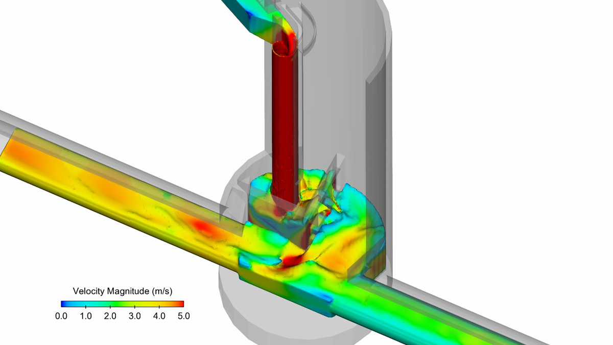
CFD modelling: View of Earl Pumping Station vortex drop shaft and storage tunnel – Courtesy of Mott MacDonald
Computational fluid dynamics modelling
CFD was the primary hydraulic modelling tool used during the initial design stages, which provided the ability to model all the hydraulic structures, incorporate design modifications, quickly visualise and analyse results and conclude on performance.
3D building information modelling (BIM) geometries of the proposed designs were transferred to the CFD software, reducing the time required to generate geometries for the CFD fluid domains.
Flow 3D, developed by FlowScience Inc, was the main modelling platform utilised. The software has the capability to accurately model the free-surface flows, applying a volume of fluid method to track the air-water interface.
A 3D structured mesh with cubic cells was utilised and turbulence was treated using the Reynolds-averaged Navier–Stokes approach with a standard k-omega turbulence model.
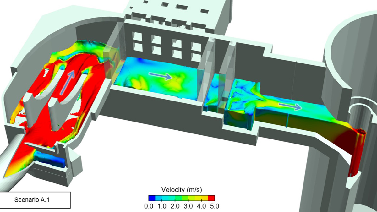
View of King Edward Memorial Park Foreshore interception structures and approach to vortex drop shaft – Courtesy of Mott MacDonald
Sensitivity analyses to mesh resolution were undertaken and the results compared with those available from previous concept stage physical scale modelling of the structures to allow inference on the suitability of computational meshes. Special care was given to meshing in areas where sharp gradients occur, such as at the throat of the vortex generator and drop tube.
A balance between overall mesh resolution and computational efficiency was required to generate solutions that were sufficiently accurate for design purposes, however crucially within timescales that met design programme targets.
Once CFD models were converged the results were visualised. Primary outputs included the detailed water levels throughout the structure, velocity plots with magnitude and vectors and flow streamlines. The data generated by the CFD models was very useful in gaining an understanding of the behaviour of the flow field and by analysing these results it was possible to conclude on how the design was performing.
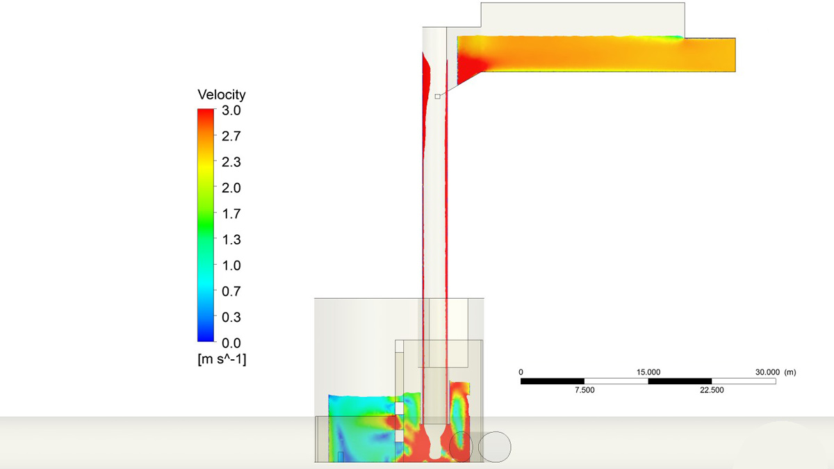
View of King Edward Memorial Park Foreshore drop shaft and energy dissipation chamber – Courtesy of Mott MacDonald
Physical scale hydraulic modelling
Physical scale hydraulic modelling was used for a comprehensive assessment of the hydraulic performance of the designs across the full range of operating conditions, and to inform and test design improvements.
For efficiency of programme, physical scale modelling was undertaken at a stage where the design of the hydraulic structures was well advanced. CFD modelling had already been performed, providing confidence to the overall performance of the designs. Key structural members had also been sized and the designs space-proofed for MEICA plant.
Carrying out physical modelling at this stage of design development aimed to reduce the risk of major changes being required to the physical models as these are very time consuming. It also ensured that model testing reflected the final intended design of the hydraulic structures as closely as possible.
Two sites were selected for physical modelling where, due mainly to space constraints, the design of the hydraulic structures was more complex. These sites were:
- Greenwich Pumping Station, where a full work-site model at a scale of 1:10 was constructed.
- King Edward Memorial Park and Foreshore, where a model of the CSO interception structures was undertaken, at a scale of 1:10, and a separate model of the drop shaft energy dissipation and de-aeration chamber was built, at a scale of 1:12.
Models were built and tested by specialist sub-contractor BHR Group in their laboratory facilities. The models were built mainly from Perspex and plywood using model drawings generated from the latest design BIM model. Before being approved for model construction, the drawings were subject to a rigorous dimensional check against the BIM model, to ensure an accurate replica of the hydraulic structures was achieved in the laboratory.
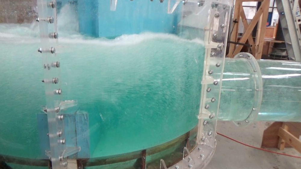
Model of King Edward Mermorial Park and Foreshore energy dissipation chamber in operation – Courtesy of Mott MacDonald & BHR Group
As the force of gravity dominates the open-channel fluid flow in these structures, it is critical that the Froude number is maintained equal in the prototype (full scale design) and in the reduced scale model to ensure similarity. Therefore, the models were operated at flow rates to maintain equality of Froude number. The scale also had to be sufficiently large to ensure that flow was fully turbulent under all flow conditions and this was checked by estimating the Reynolds number of the flow in different parts of the model.
In a reduced scale physical model, it is not possible to eliminate all scale effects. As surface tension does not scale, the Weber number (representing the ratio between initial forces and surface tension) of the prototype and model are different and so is the quantity of air entrained in the liquid phase between both. This is recognised and understood to be a limitation of the method and was addressed by application of a scaling factor to the air entrainment results.
The model was subject to testing in accordance with a pre-defined testing matrix setting out operational cases. These comprised various flow cases and storage tunnel tailwater levels. Flow rates were strictly controlled by calibrated instruments and, where necessary, flow into the model was conditioned to ensure flow in the area of interest was not artificially affected by inlet conditions.
The behaviour of the flow was observed and recorded:
- Water levels were recorded by means of pressure tappings or visually, aided by vertical scales on the side wall of the model.
- Flow patterns were recorded visually, aided by dye tracers.
One aspect of particular interest was the vortex flow. Detailed observations of the flow through the vortex generator and vortex drop tube were observed to ensure the flow was stable, free of pulsating transient effects, and that the vortex flow formed well in the drop tube maintaining a stable air core throughout the range of flows.
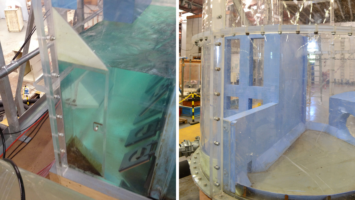
(left) Physical model of Greenwich Pumping Station interception chamber flap valves in operation and (right) physical model of Greenwich PS internal structures for energy dissipation within the shaft – Courtesy of Mott MacDonald and BHR Group
Since critical flow occurs in the vortex generator, a definitive head-discharge relationship is established, presenting an opportunity to measure flow by reading the water level. A pressure tapping located in the approach culvert to the vortex generator recorded water depth values across the range of flow rates, allowing a head-discharge curve to be derived for each drop structure. In the prototype, the level signal collected at this point will be used to calculate flow and control the isolation gates.
As the flow drops many metres down the vortex drop tube and impinges into the water pool at the base of the drop shaft, air is entrained into the water. It is critical that the amount of air passed from the drop shaft to the storage tunnel is minimised to avoid issues with pressurised air pockets developing in the tunnel system and reduction of storage capacity. To achieve this end, it is very important that the base of the drop shaft performs a function of energy dissipation and de-aeration of the flow. This was achieved by sizing of the shaft to provide sufficient volume and also by design of the shaft internal walls to condition the flow such that:
- A plunge pool was formed.
- Flow paths/retention time in the shaft are as long as possible.
- Specific areas of the base of the shaft promote an upwards flow path.
These measures aim to ensure the energy of the falling water is dissipated and air entrained disengages from the flow, as much as possible, before being passed on to the storage tunnel.
To assess the performance of the energy dissipation and de-aeration structures, the air flow passing from the drop shaft to the storage tunnel was measured by a method of water displacement. To ensure the correct amount of air entrained in the flow, the models incorporated the full height of the vortex drop tube. For acceptability criteria of the designs, the maximum air flow was limited to a pre-defined value, defined as a percentage of the maximum design water flow. To account for scale effects, the maximum acceptable amount of air flow in the model was reduced by a factor of around 6 times compared to the prototype.
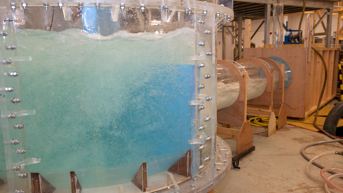
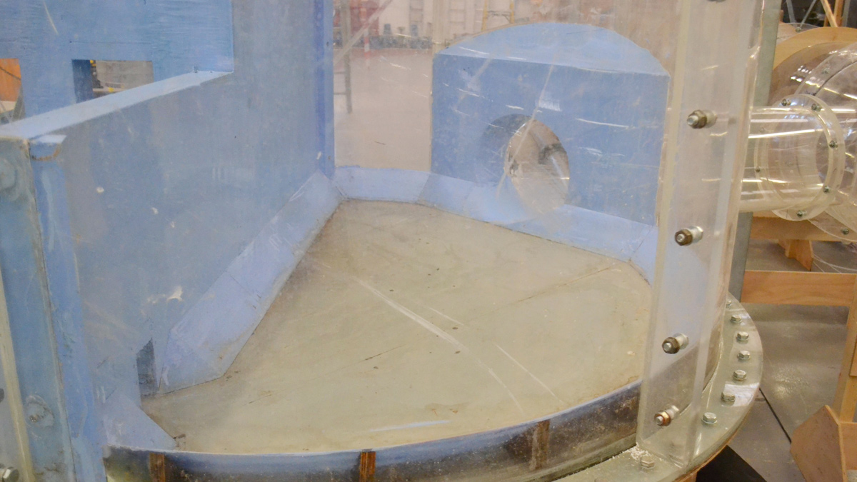
Physical model of Greenwich PS showing energy dissipation chamber and entrance to connection tunnel – Courtesy of Mott MacDonald and BHR Group
The physical scale modelling also tested sediment mobility through the structures. This was achieved by dosing the model with an amount of simulant, scaled to match the expected particle size distribution occurring in the sewerage network.
Design improvements in the models comprised mainly adjustments to the shaft internal structures, to improve de-aeration performance, and inclusion of benching and other measures to aid sediment mobility. These improvements were confirmed by re-testing and then incorporated in the design. Data from the physical modelling was compared with the results from the CFD modelling with good agreement observed.
The final modelling results have shown that while a large degree of turbulence occurs close to where the flows are diverted from the existing sewer network, the interception chambers were sufficiently sized to partially dissipate this energy and, with the inclusion of certain hydraulic design elements, no problematic hydraulic behaviour was observed close to the mechanical equipment. At higher flow rates, some air entraining vortices formed in the bulk of the fluid. However, given the occasional nature of these high storm flow rates these were not anticipated to cause deterioration of the concrete structures. The results also indicated that the structures have the capacity to divert the maximum design flows to the Thames Tideway Tunnel, preventing spills through the existing retained CSOs. The linear connection culverts which link the interception chamber with the vortex drop shaft had a positive effect in conditioning the flows and the operation of the vortex drop tube was observed to be stable across the range of flows.
Conclusions
The design of the hydraulic structures for the Thames Tideway Tunnel involves complex 3D turbulent flow behaviour that has required advanced hydraulic modelling tools to be used during the design stage. CFD modelling has allowed for the testing and modifying of the proposed designs so that the design flows are accommodated safely and within the required performance parameters.
The main benefits of utilising CFD on this project were the ability to carry out hydraulic modelling in a comparatively short timescale, the usefulness of the data generated and the ability for it to be visualised, which has helped to inform and confirm the designs. CFD modelling was a valuable tool to design these hydraulic structures set within a constrained urban environment.
Physical Modelling – View of King Edward Memorial Park and Foreshore Energy Dissipation Chamber – Courtesy of Mott MacDonald and BHR Group
Physical modelling was carried out due to the criticality of the structures, to enhance confidence in the results and to further study aspects of hydraulic performance where CFD presents limitations. The physical models also proved useful to demonstrate to stakeholders exactly how the flow is performing inside the structures. Additionally, given that model testing mostly reflected the final design, a record is kept of the hydraulic performance of the structures.
Timescale
The excavations for four of the five shafts are ongoing or complete and the first base slabs and secondary linings will be poured in the shafts before the end of the year. The TBM for the main tunnel, Selina, will begin its final journey to site at the end of the year with tunnelling commencing in 2020.