
Thames Water AMP6 Pressure Management Programme (2019)
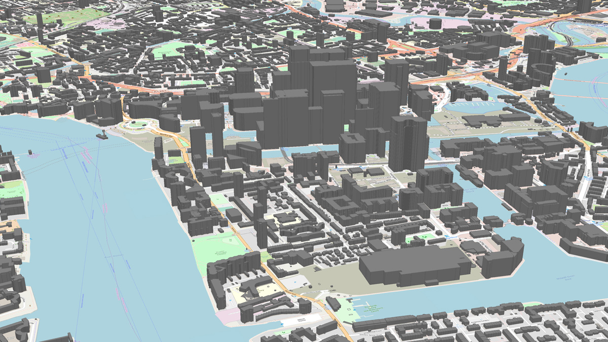
Example of 3D digital terrain model (Isle of Dogs, London) - Courtesy of SMB JV
Thames Water’s water distribution network totals some 31,000km of mains that provides about 2.6 billion litres of water every day. This network has been built up over many years and includes pipes that were laid during the Victorian age. Pressure management is an established way of leakage reduction and network protection, ensuring that customers receive the required level of service whilst minimising the amount of water lost from the network.
Introduction and overview
Thames Water have undertaken pressure management programmes during AMP6 as part of its overall effort to reduce leakage. These schemes can often be small in terms of the amount of construction work involved. However, this apparent simplicity is misleading as all schemes require detailed analysis, design, construction and implementation to address the individual set of circumstances and challenges they present.
Schemes can be divided into two overall categories, simple schemes at district metered area (DMA) level and more complex schemes containing many DMAs. The simple schemes involved the creation of a pressure managed area (PMA) within an existing DMA. The following steps were followed:
- Identify a high-pressure area within a DMA.
- Undertake field tests to verify the understanding of the network.
- Assess the topography and buildings within the proposed PMA to understand any potential impact on supply.
- Hydraulic modelling of the proposed PMA.
- Create the PMA boundary by closing existing and new valves.
- Managing pressures within the PMA using control valves linked to pressure control points.
The more complex schemes were undertaken on the trunk mains that feed DMAs. These schemes often delivered significant leakage reduction; however they usually included some zonal reconfiguration and the added challenges that this can bring.
All schemes required a review of tall buildings with their area of influence. If a building was identified at risk of low pressure, then the installation of a booster pump or another solution was considered in order to maintain the level of service. The number of booster/solutions was often the most significant commercial constraint on a scheme proceeding.
Scheme identification
Potential schemes were identified in two ways; through analysis using zonal three-dimensional analysis including hydraulic models, and through knowledge of the local distribution network. During AMP6 the pressure management team created 3D models of the Thames Water region including both topography and buildings. This was combined with hydraulic network models to identify Available Pressure Reduction profiles.
In parallel with the above, the team also developed a database holding information on tall buildings. Buildings considered at risk were surveyed to determine if a solution was needed. The survey data was collected in the field on handheld tablets/smart phones using an application developed by the team. Survey data was uploaded directly to the database after a digital validation.
Once a potential scheme was identified it was included in the three-dimensional model and analysis undertaken. The figure shows an example of the three-dimensional modelling, the buildings impacted by a scheme under consideration are easily seen. Hydraulic modelling was carried out to assess any impact on the level of service. Fieldwork data was also used to verify the hydraulic model and ensure that the proposed PMA could be implemented.
Scheme design
During the design stage the team dealt with many challenges, these can be summarised as (i) Operational, (ii) Third Party and (iii) Engineering.
Operational challenges: The pressure management schemes were implemented onto a live distribution network. To be successful both in the short and long terms, operational issues needed to be addressed, the most typical were:
- Other programmes: Ensuring schemes were compatible with other programmes in the area and that the team had knowledge of both short and long-term changes (for example, mains renovation, valve operation from other teams whilst the field tests are being carried out).
- Continuity of supply: Customer interruptions had to be avoided or kept to a minimum, schemes were designed are designed to accommodate this.Network operation: Early engagement with the network engineers was essential, they are responsible for the long-term operation of the schemes.
- Water quality: There was a risk that the creation of a PMA could create ‘dead legs’ within the network, some water mains that had been unused for significant periods of time were brought back into use and flow velocities altered in others. All of these had the potential to create a water quality issue and needed to be managed by the team to avoid this.
- Ongoing operational issues: During the course of the project the team has to ensure that they took account of the day to day operational issues presented by a large urban network, for example breached boundaries, meters reporting erroneous data, operational contingencies. Issues were resolved during the design stage.
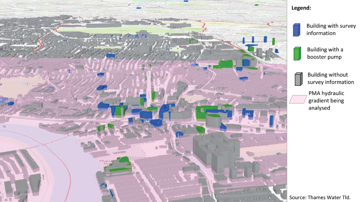
Example of central London scheme (Source Thames Water) – Courtesy of SMB JV
Third party challenges: Most of the schemes delivered were in London, in heavily congested urbanised areas. It was very unusual to have a scheme where the proposed works could be designed without considering a range of third-party issues, including:
- Other services, these were present at all the sites worked on. No diversions of services were carried out and the team had to ensure that the proposed works could be constructed safely and without disruption to other services. Thames Water have a set of ‘Life Saving Commitments’ relating to the delivery of its capital programme and one of these is related to high risk services. A hierarchy of risk reduction was followed:
- Hazards presented by high risk services were avoided through design.
- Owners of high risks services were contacted to determine if isolation of their services was possible.
- Only then was work undertaken adjacent to live service following strict control measures.
- Other third-party issues included; environmental, planning, archaeology, contamination and private land. A dedicated team carried out a screening process to ensure that any such issues were identified and where necessary addressed before construction took place.
- Consultation with local authorities ensured that their plans, requirements and permits were both taken into account and were in place. These included alterations to bus routes, suspension of parking bays, alteration of pedestrian routes, road closures and traffic management arrangements at individual sites. The latter could include restrictions on traffic movements into and out of the working area, for example, no vehicles permitted between 6am and 8pm.
Engineering challenges: Although the scale of most schemes was relatively modest, several technical challenges were presented:
- Space, rarely if ever did the team have a scheme where this was not an issue requiring careful consideration. The designers had to ensure that enough new assets be included to allow the future operation of the network. This includes the provision of line valves, hydrants, meters, control valves, monitoring points, bypasses and straight lengths of pipe up-stream and downstream of meters. Some of these assets can be buried, however others require the construction of significant chambers.
- Most of schemes were implemented on old cast iron mains and the condition of these main was a risk. On large schemes trial excavations were carried out and the condition of the mains determined through non-destructive techniques.
- All the schemes changed the layout and operation of the network in a way that could introduce new thrust forces. These had to be restrained to ensure the safety and integrity of the network. Construction of large scale thrust blocks in urban areas is usually impractical and in London this is often compounded by the presence of made ground.
The design team overcame these issues by developing a design that included a reinforced concrete slab beneath the PRV installations that resisted any thrust forces by generating friction against the underlying soil. Geotechnical parameters were initially determined through desk study and then verified through trial excavations when possible or during the early stages of construction.
Throughout the design process the design engineers worked very closely with Thames Water operations staff and the construction staff to ensure their views and requirements were considered. This is essential to the successful delivery of the programme.
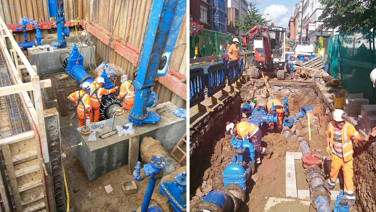
(left) Major London pressure management scheme and (right) typical London pressure management scheme – Courtesy of SMB JV
Scheme construction
The construction team were involved in the schemes from early in the design process. When a scheme reached the construction stage, it had a fully detailed design and plans were in place for all known constraints and issues. This allowed the team to develop a detailed construction plan for each scheme.
Most of the schemes required work in the highway and it was in all parties’ interests to keep the duration of these works as short as possible. The team placed advance orders for all materials and operated a just-in-time approach to deliveries as site storage was often limited. This proved to be invaluable during the programme as restrictions on working areas and traffic movements were placed on several sites.
Although the team made their best efforts to mitigate risks through the design stage there were several occasions where existing water mains and other services were not in the locations expected or shown on GIS records. The experience of the team meant that they expected situations like this to arise. When such issues occurred the designers attended site to work with the construction team and develop a solution that allowed construction to proceed.
Conclusions
During AMP6 pressure management has been an effective way of controlling leakage. When compared to other schemes in the capital programme the scale of construction work can appear relatively minor. However, the success of the pressure management programme has relied upon the innovative use of technology and data together with high levels of understanding and collaboration between network operators, designers and the construction team.