
Tideway Central – Main Tunnel Primary Lining (2021)
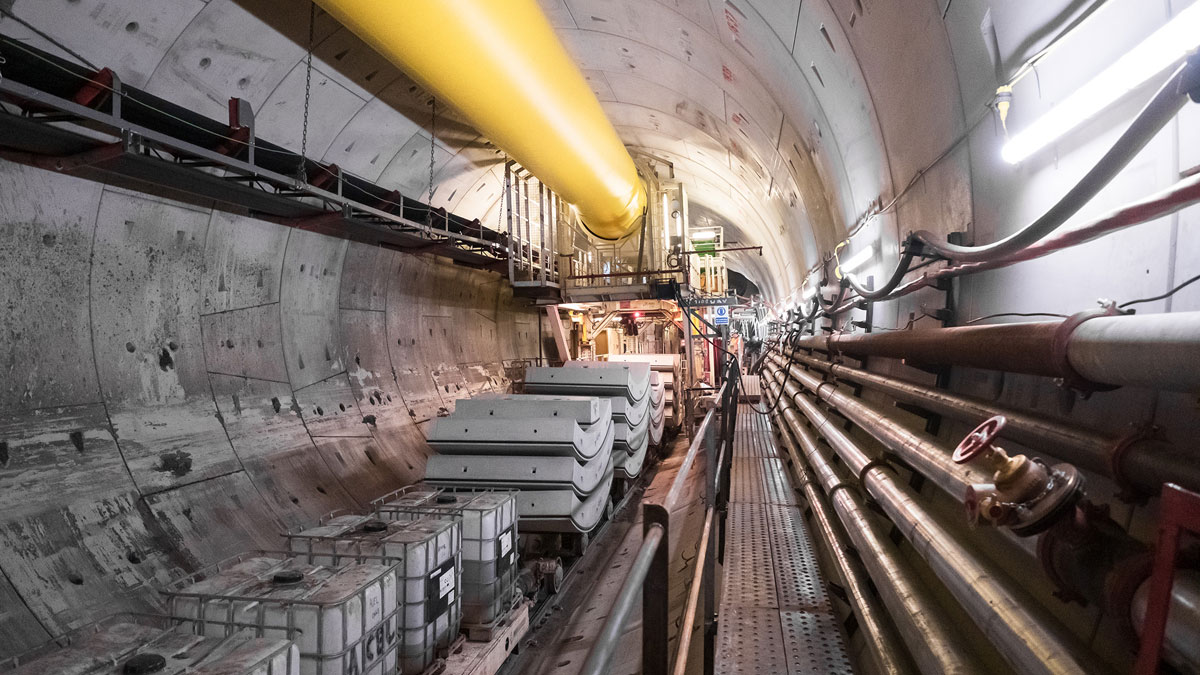
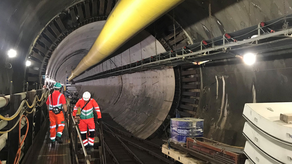
Kirtling Street shaft concrete segments entering the tunnel from the shaft - Courtesy of Tideway/FLO JV
The Tideway Project is a 25km long combined sewage storage and transfer system along the River Thames in central London, UK. The project is split into three design and build contracts with the limits of each contract determined primarily by geology along the alignment. The contract for the Central Section, the longest and most challenging of the three, consists of 12.7km of tunnel and eight work sites with deep inlet shafts and ancillary structures. The Central Section tunnel primary lining has an internal diameter of 7.8m and has been constructed using mainly steel fibre reinforced precast segmental lining. The construction of the primary lining was completed at the end of 2020. Currently a fibre reinforced concrete secondary lining is being constructed bringing the finished internal diameter down to 7.3m. The tunnel primary lining is required to be able to sustain high internal surge pressures and to limit water ingress and egress through the joints to a negligible amount without the contribution of the secondary lining. The biggest design challenge was to produce a single design solution for the primary lining crossing different ground conditions.
One tunnel lining solution for the whole central section drive
One of the main challenges encountered during the design of the main tunnel lining was to provide a unique solution for the lining that would satisfy structural and minimum watertightness performance requirements without the contribution of the secondary lining to improve time and cost efficiency. Internal loading conditions varied from empty case to a maximum internal surge pressure and together with an extensive variability in the external ground conditions they would impact the tunnel lining in many different scenarios.
As the tunnel lining would act as the primary means of watertightness, extensive analysis was carried out to assess the potential opening of the joints during the maximum internal surge.
The primary lining of the main tunnel was proven to be able to meet both the structural and watertightness requirements independently and therefore the cast in place fibre concrete secondary lining was only required to provide additional durability assurance in accordance with the works information of the project which required a two-barrier system to meet structural, watertightness and durability requirements.
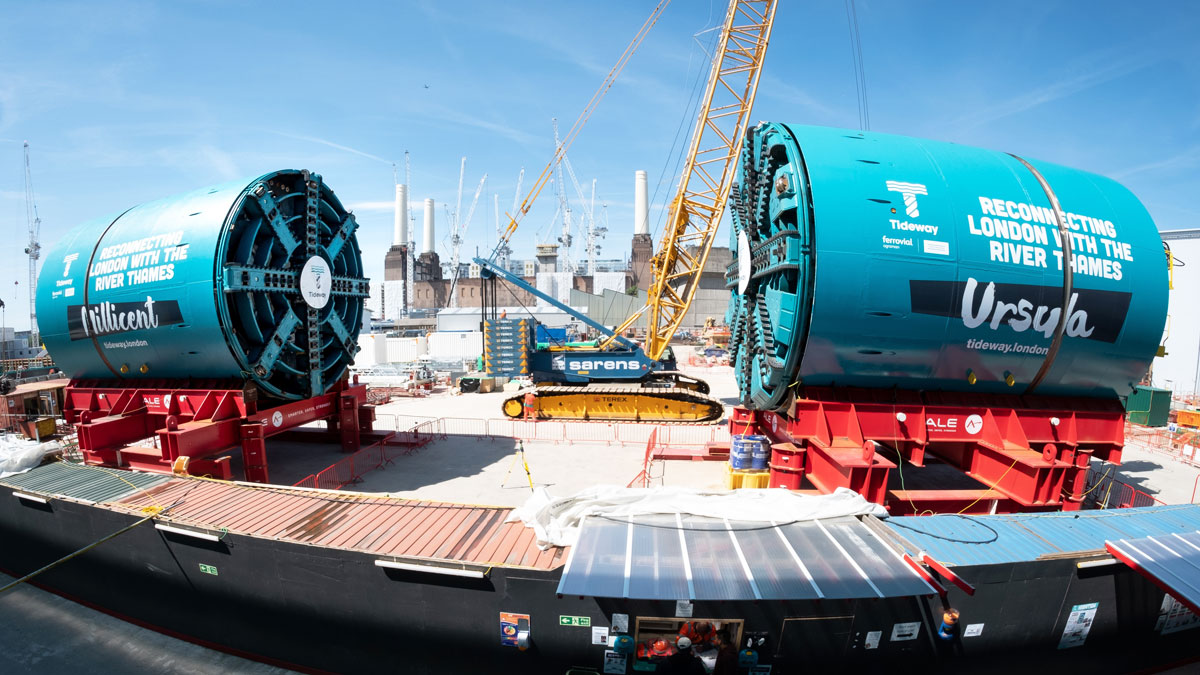
The tunnel boring machines ‘Millicent’ and ‘Ursula’ – Courtesy of Tideway
Primary tunnel lining
The tunnel was excavated and constructed using an earth pressure balance (EPB) tunnel boring machine (TBM). The cutting head diameter was 8.84m, providing a 61.4m2 total cutting face area. Behind the cutting head, the shield had a length of 11.1m and a diameter of 8.78m. This difference in radius between the cut radius and the diameter of the tail skin creates an annulus of 30mm which allows for the ground deformation and settlements to occur.
During the excavation, the TBM applied a face pressure to balance the forces within the ground and to control the ground deformation and settlements. The pressure is applied by regulating the volume of spoil in the plenum and by rams, which allowed the TBM to advance. The working limit of the TBM maximum operating pressure was 5.3bar (530kPa). As the TBM advanced, the precast concrete segmental rings were installed to form the primary lining. Each ring has five ordinary segments, two top segments and a key with internal radius of Ri=3900mm and a thickness of each segment of Ts=350mm.
After the erection of the ring, the 170mm annulus between the excavation diameter and the external diameter of the lining was grouted through the tail skin. All segments contain steel fibre reinforcement, with additional traditional rebar reinforcement cages incorporated where a more robust ring was required, such as at the first 10 rings and last 10 rings of each drive, at the junctions with the connection tunnels, either side of the Blackfriars Shaft site and where drift filled hollows (pingos) would have been encountered.
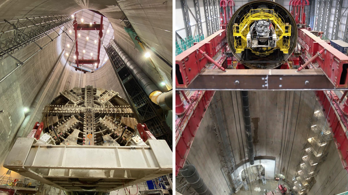
(left) TBM Ursula leaving the Chambers Wharf shaft after completion of the tunnelling works and (right) lowering of TBM Millicent at Kirtling Street Shaft to start the tunneling works – Courtesy of Tideway/FLO JV
The segmental tunnel lining has been designed to sustain external and internal water pressures of up to 6 bar associated with maximum surge event corresponding to an internal hydraulic grade line of 104m ATD as per works information requirements, limiting water ingress/egress to a negligible amount. The seal is created by the inclusion of cast-in ethylene propylene diene monomer (EPDM) gaskets in all segments. The gaskets are supplied as a continuous loop with the joints formed to the correct angles for each type of segment. Furthermore, the joint formation has been designed to minimise the additional rubber material forming the joint to avoid hard spots in the gaskets. The gaskets were pressure tested to 10 bar pressure with 10mm offset and a 3mm gap between bearing surfaces in a rig to model a cruciform joint arrangement.
Geology and groundwater conditions
The Tideway Central main tunnel lies within the geological province of the London basin and covers a range of different ground conditions. The geological stratigraphy that the main tunnel encountered during its excavation, from west to east, transitions from London Clay into Lambeth Group with interlayers of cohesive and granular strata, through the Thanet Sands with interlayers of sand and silty deposits before reaching the Chalk strata at Tideway East’s Chambers Wharf site.
Groundwater is present in the surface superficial deposits of alluvium and the River Terrace Deposits, supported by the underlying, low-permeability London Clay Formation. This is referred to as the upper aquifer and it is tidally influenced by the River Thames.
Groundwater is also present in the Harwich Formation at the base of the London Clay, in granular units in the upper section of the Lambeth Group and particularly in the Channel Sands. These variable water-bearing strata are collectively termed the “intermediate aquifer”.
The main water-bearing sequence is known as the ‘lower aquifer’ and comprises of the Chalk, the overlying Thanet Sand Formation, the granular Upnor Formation and Lower Mottled Beds which form the basal units of the Lambeth Group.
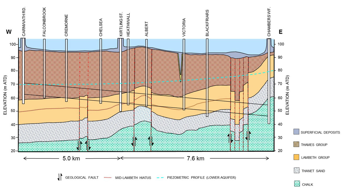
Geology for Tideway Central Contract main tunnel and shafts – Courtesy of Tideway
Design loadings
During the design of the main tunnel, two different ground water profiles were assumed for higher and lower groundwater conditions accounting for the rising and lowering of the lower aquifer in the future. In addition upper and lower bound geotechnical parameters were considered during the design including the maximum and minimum earth pressure coefficient (Κ0,min, Κ0,max).
All the load combinations were simulated for upper and lower bound geotechnical parameters and maximum and minimum groundwater level and included the following loadings:
- Maximum internal water pressure.
- Primary and secondary grouting pressure.
- Operational surface surcharge at ground level.
- Allowance for future development at ground level.
Temporary handling and stacking loads, gantry wheel loads, ram forces and the effects of steps, lips and ring build tolerances were considered using separate empirical calculations. Seven characteristic geological sections, considering full face ground conditions or mixed face ground conditions were investigated along the whole route to reflect different ground conditions where the effect of the above loads was assessed.
Numerical analysis
In line with current best design practice for this type of structure, two different numerical modelling packages have been used. The soil-structure interaction modelling was carried out using the geotechnical finite element software PLAXIS 2D. This software was used to indicate the worst design scenarios for the tunnel lining where only the effect of radial joint was taken into account.
In addition to the PLAXIS analyses, a structural model using LUSAS 3D software with both radial and circumferential joints modelled explicitly was developed to investigate the influence of the segment joints on the behaviour of the lining.
The purpose of these analyses was to assess the behaviour of the primary lining under all loading conditions, in particular during the surge mode and the influence of this loading on the lining joint, without considering any contribution of the secondary lining.
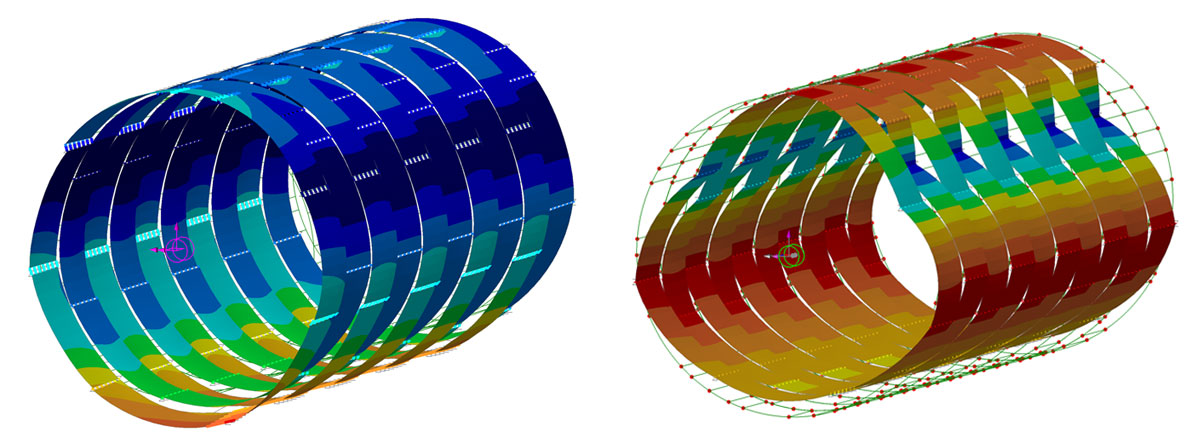
Radial displacements on the LUSAS Model (left) with and (right) without internal pressure – Courtesy of AECOM
2D analyses in PLAXIS
The soil models are always an approximation of the real soil and therefore it is important to consider the possibilities and limitations of models in view of the specific application. The capacity to accurately reflect field conditions depends on the ability of the constitutive model to represent soil, boundary conditions and construction sequence correctly therefore the choice of the soil model has large implications on the design of the structure.
Two typical soil models were used to simulate the soil behaviour; the Mohr-Coulomb (MC) and the Hardening Soil (HS). For the design of the precast tunnel lining, superficial deposits were modelled with Mohr-Coulomb model which represents soil stiffness in the in-situ stress state. However, to account for stress-dependency of the stiffness moduli when the soil stiffness increases with stress, the soil constitutive model for Thames Group, Lambeth Group, Thanet Sand and Chalk were based on Hardening Soil model.
Both tunnels were constructed with the use of an EPBM which provides a support pressure to the tunnel face during the excavation to counter balance the earth and water pressure acting at the face of the excavation. The provided support face pressure minimises the movement of the surrounding soils and subsequently the surface settlements. However, an amount of the soil mass around and ahead of the excavation will relax inducing a 3D phenomenon.
As a result of the relaxation of the surrounding soil mass, a radial displacement around the excavation will occur, leading to increased strain values around the excavation and consequently reduced stiffness of the surrounding soil.
In order to simulate the effects of this three-dimensional effect, a range of relaxation values, based on the solution proposed by Panet (1979) were considered for each material type and adopted in the 2D finite element (FE) analysis, considering the properties of the surrounding soil, the radius of the tunnel and the method of construction. The tunnel lining was modelled as curved plates and was characterised by linear elastic two-dimensional plate elements with axial, shear and flexural resistances.
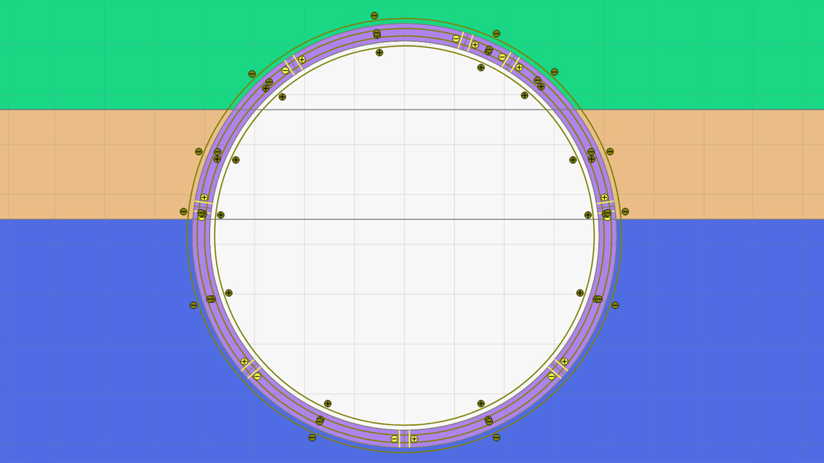
PLAXIS 2D analysis: Volume element, radial joints and mixed ground face – Courtesy of AECOM
The lining was assigned with isotropic stiffness properties and was modelled as a plate with no joints and the effect of the joints between segments of the tunnel lining was modelled by reducing the effective stiffness. The effective lining stiffness was calculated using the approach proposed by Muir-Wood (1975).
A second analysis was performed with the tunnel lining modelled as volume elements and was characterised by linear elastic two-dimensional volume elements with axial, shear and flexural resistances. The primary lining was assigned with isotropic stiffness properties and was modelled with joints between the segments, which were prescribed with compressive and shear capacities, but zero tensile capacity. The aim of this additional analysis was to simulate the actual opening of the joints between the segments.
Tideway Tunnel – Central Section: Main tunnel primary lining: Supply chain – key participants
- Project manager & principal designer: Tideway (Jacobs)
- Principal contractor & lead designer: FLO JV
- Main designer (permanent works): AECOM
- Durability consultant: OTB Concrete
- CAT III checker: Arup Atkins Joint Venture
- Main tunnel contractor: FLO JV
- Instrumentation & monitoring contractor: FLO JV
- Precast concrete segmental lining: Pacadar
- Tunnel boring machines: NFM Technologies
- Steel: Express Reinforcement
- Steel: Arcelor Mittal
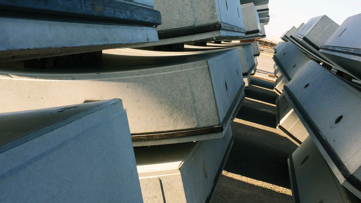
Precast concrete segments stockpiled in courtyard – Courtesy of AECOM
3D analyses in LUSAS
The 3D finite element software LUSAS was used to create three models to investigate the influence of the segment joints on the behaviour of the lining. For each model, spring supports, with stiffnesses derived from PLAXIS 2D output, were used to represent the interaction between the lining and the surrounding ground.
In the first LUSAS 3D analysis the tunnel lining was modelled as a continuous ring with no joints between the segments but with orthotropic stiffness to incorporate the effect of the joints between the segments as used in the PLAXIS 2D analysis.
In the second LUSAS analysis the tunnel lining was modelled as a shell element introducing joints between the segments with only compressive, but no tensile capacity in order to simulate the actual opening of the joint when the lining was subject to internal pressure.
In the third LUSAS analysis, the tunnel lining was modelled as consecutive segmental rings using dowels in the longitudinal direction to connect the rings. The consecutive segmental rings were modelled as shell elements introducing radial joints between the segments with compressive capacity but no tensile capacity.
TBM frame at the Kirtling Street shaft – Courtesy of AECOM
Conclusions
For all models the stresses in the lining were within the capacity of the 350mm thick fibre reinforced precast concrete tunnel section under all loading conditions ignoring any possible contribution from the secondary lining.

Joint opening predictions
With particular consideration to the internal surge, where the lining would try to expand and opening the joints undermining the watertightness requirements, it was possible to demonstrate that the predicted joint opening for the most onerous scenarios was within the 3mm limit which the gaskets were tested for and therefore indicated that the primary lining alone is able to provide sufficient watertightness during the most extreme surge event.