
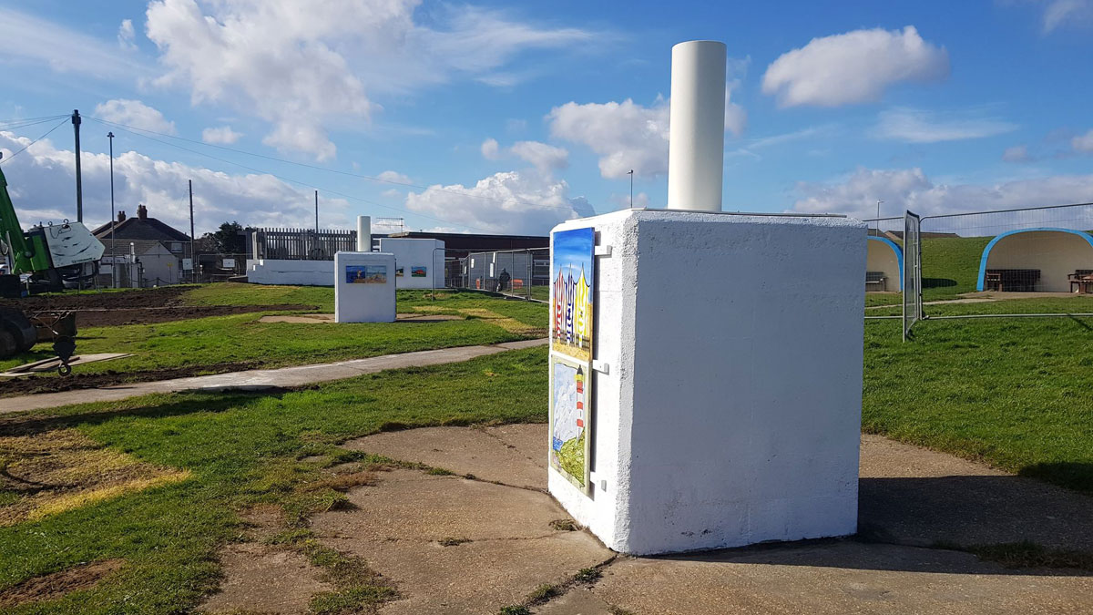
Trusthorpe Outfall (2021)
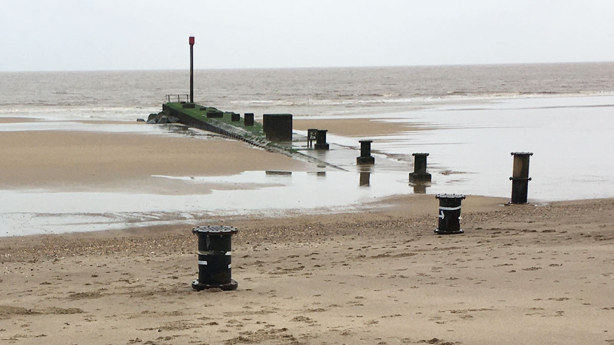
Trusthorpe outfall - Courtesy of Royal HaskoningDHV
The sea defences along the coast of Lincolnshire mainly comprise of concrete seawalls fronted by sandy beaches providing flood protection to the low-lying coastal flood plain, which extends up to 15km inland and has a recorded history of inland flooding as far back as the 13th century. The Lincolnshire Open Coast Flood Risk Management Scheme was developed in the early 1990s to reduce the risk of flooding by artificially recharging the beach to a design profile. This process initially built up the beach and an annual recharge maintains the beaches and the standard of protection provided by the defence system. The scheme protects urban, agricultural land, residential and commercial/industrial properties, static caravans, various environmental assets and the coastal resorts of Mablethorpe and Skegness.
Background
Along the Lincolnshire coast, several outfalls cross the sea defence to provide drainage of the low-lying hinterland. The outfall control structures are an integral part of the sea defence system. One such outfall is located at Trusthorpe, to the south of Mablethorpe. The existing Woldgrift Drain discharges to sea via a concrete box culvert that passes beneath the main road and coastal defence. Located adjacent to the drain is the Trusthorpe Pumping Station, operated by the Internal Drainage Board (IDB), which pumps the flows to the culvert during high tides when gravity flows cannot be achieved due to closure of the tidal gate. A high tidal surge event on 5th December 2013 resulted in flooding inshore of the coastal defences at Trusthorpe affecting a number of properties and closing the main A52 Sutton Road. Flooding was observed from the existing main sluice chamber adjacent to the IDB pumping station.
The Environment Agency and Team Van Oord, a joint venture of Van Oord, Mackley, Royal HaskoningDHV and Kier, were tasked with investigating and identifying the root cause of the flooding event, with a view to designing, constructing and implementing a long term solution to prevent future flooding. The works were integrated into the planned 2020 beach recharge campaign.
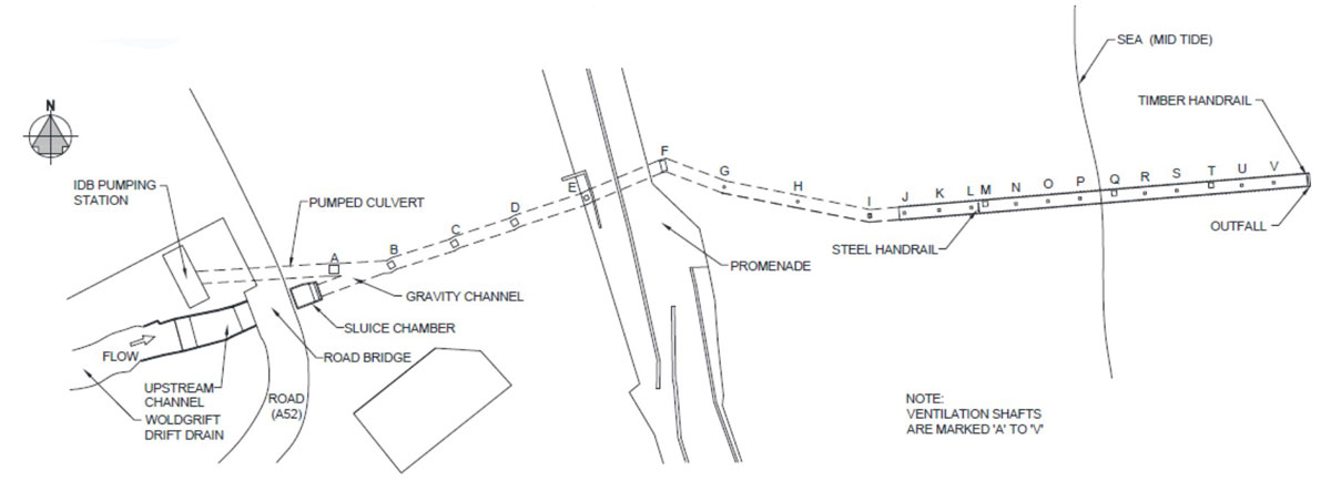
Site schematic – Courtesy of Team Van Oord
Existing outfall
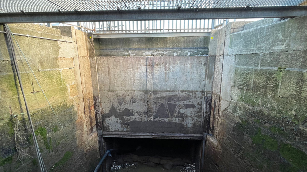
The Woldgrift Drain is an open channel that diverges upstream of the A52 Sutton Road and IDB Pumping Station. The discharging flows pass through a coarse debris screen, under the road and into a sluice chamber with a tidal flap valve on the upstream entrance. On high tidal conditions this flap valve will close and retain flows upstream and subsequently divert flows to the IDB pumping station well. On the downstream exit of the sluice chamber was a wooden guillotine gate which had historically been used for flushing the downstream culvert. The flows continue offshore through a rectangular culvert under the flood protection and beach to a discharge location close to low water. Along the length of the culvert there are a number of access chambers and ventilation shafts. It is understood that one of these chambers, Chamber F located on the beach at high water, used to contain a tidal flap valve but this was no longer operable due to corrosion some years ago.
The IDB Pumping Station is located on the upstream side of the A52 Sutton Road and receives flows during high tides and high fluvial flow conditions. The IDB pumps operate by level control discharging flows to a separate chamber and pipe that connect to the outfall culvert downstream of the sluice chamber.
Woldgrift Drain and chambers – Courtesy of Royal HaskoningDHV
The flooding event
The flooding event under consideration occurred on the evening high tide 5 December 2013 when a significant tidal surge was experienced. The peak tide recorded was +5.119mOD at 18:59 GMT. The predicted high tide that day was +3.76mOD (+7.51mCD) at 19.33 (MT, therefore the extreme event indicated a 1.36m tidal surge occurred during the high tide.
This tidal surge resulted in the incoming tide overflowing at the main sluice chamber, which itself resulted in flooding of the A52 Sutton Road, which is an emergency access/egress road, and adjacent properties. A comparison of the peak tidal level and the existing chamber levels on the culvert confirmed that the cause of the flooding was a result of tidal ingress into the culvert. The peak tide level achieved was above all the existing culvert chamber coping levels except two (Chambers A and D). It was also confirmed that the IDB pumps were not in operation during this event.
The solution
A preliminary assessment of possible remedial options to prevent future flooding of the outfall culvert inland of the coastal defences was undertaken. The following options considered either prevented tidal ingress into the culvert or raising the height of the system above the predicted hydraulic profile during operation of the pumps:
- Additional of a tidal flap valve and penstock in chamber F (on the beach): The existing chamber shaft had insufficient space available to install and maintain such a valve/penstock arrangement. For this option to be implemented, either the existing chamber had to be enlarged or a new chamber constructed offline for the valve/penstock to be fitted.
- Duckbill valves fitted to the discharge end of the culvert: The duckbill valves would be fitted to a steel plate and frame installed onto the end of the existing culvert. The valves would allow the Woldgrift Drain flows to be discharged whilst preventing tidal ingress.
- Chamber raising: Raising the coping levels of the existing chambers A to E and the sluice chamber above the peak predicted water level in the outfall culvert. The hydraulic analysis estimated that this level would be above the wet well roof of the IDB Pumping station.
- Seal chambers: Removing the open covers to the existing chambers A to E and the sluice chamber and replacing them with bolted covers to provide a watertight seal. This would effectively turn the culvert into a pressure system. Air valves would be required in multiple locations to provide venting to the culvert during flow discharges and incoming tides.
Hydraulic analysis was undertaken of the IDB pumping station discharging to a submerged culvert (high tidal conditions) to predict the upstream water levels in the culvert and associated chambers. The hydraulic analysis confirmed there remained a potential for flooding to occur more frequently if multiple pump operation occurs during extreme high tide conditions.
Taking into consideration the various advantages and disadvantages for each of the design options based on the information available at the time, the installation of flap valves on the discharge location at low water was considered most cost beneficial and lowest risk solution. It was recommended that dimensional surveys and investigations of the existing culvert and chambers were undertaken prior to further developing the preferred scheme design.
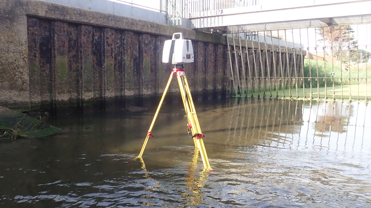
Site investigations and surveys – Courtesy of EDS Surveys
Site investigation
The requirement for further site investigations had been identified and these included a detailed condition and dimensional survey of the culvert discharge location and grill during low tidal conditions. A laser scan and topographic survey of the sluice chamber, Woldgrift Drain and IDB pipeline were undertaken during August 2018 as no historical drawings were available of the culvert or chambers. These surveys confirmed that the culvert changes internal dimensions downstream of the sluice chamber from 2.0m x 3.6m to 2.0m x 3.0m.
Further, an internal confined space inspection of the sluice chamber was undertaken to assess its structural condition and if any strengthening or remedial works were required. Consultation with the IDB pumping station owners was also undertaken to confirm the pump capacities, control and isolation procedures.
Design progression
Following completion of the surveys and chamber inspections, Team Van Oord undertook the hydraulic analysis for the preferred solution of installing flap valves on the discharge location. The reduced size of the culvert at this location only allowed a combination of smaller diameter non return ‘duck bill’ valves to be fitted. The hydraulic analysis confirmed that the resulting hydraulic performance and upstream head loss increased the risk of flooding and this no longer provided a viable solution. Further discussions were held by the project team to determine a revised solution to the flood risk looking to utilise the existing chambers upstream of the flood defence. This focussed on utilising or replacing the existing guillotine valve on the downstream wall of the sluice chamber.
Upstream dam completed – Courtesy of Jacobs
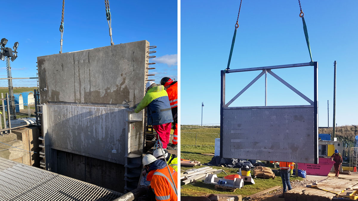
The revised preferred solution developed and agreed was to install a precast concrete wall to the downstream wall of the existing sluice chamber. This new concrete wall would facilitate the installation of a new penstock gate that when closed, would provide the required tidal barrier during periods of extreme high tidal surges. In addition, three of the existing chambers downstream of the penstock, these providing ventilation and access to the outfall culvert, would be modified to increase their height above the predicted tidal surge levels. This solution was able to utilise existing chambers on the landward side of the sea defence therefore avoiding any work being undertaken on the beach requiring associated marine licenses.
The design of the penstock gate and concrete wall modifications was developed to utilise precast and off-site fabrication techniques where possible. This reduced the quantity and duration of work required to be undertaken within the sluice chamber that would be subject to tidal and fluvial flow constraints. This was particularly appreciated by the construction team as delays with fabrication meant that the works were undertaken later than planned – in January, when tidal and fluvial flows are generally at their peak.
The penstock was also to be supplied with a fixing frame that would be cast into the concrete wall during off-site fabrication, reducing the installation time of the penstock within the chamber. This reduced the risk of misalignment of the penstock and the need for in situ drilling of anchor bolts. The modifications to three of the downstream chambers were also to be fabricated off-site to reduce the work required during the construction phase.
Sluice chamber prior to penstock installation – Courtesy of Royal HaskoningDHV
Constraints
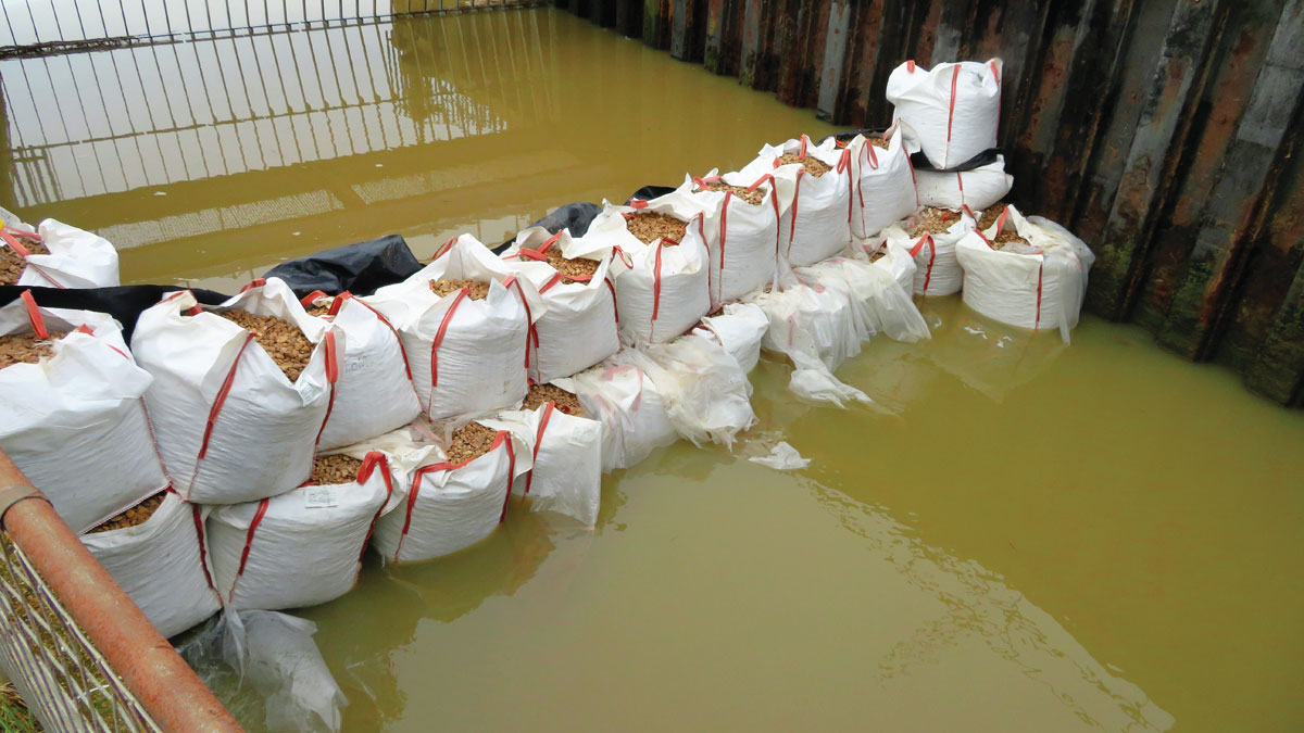
The Woldgrift Drain and Trusthorpe culvert are located on a small parcel of land to the south of Mablethorpe, on the A52 Sutton Road connecting to Skegness. As the A52 is classified as an emergency access/egress route it must remain open to traffic at all times, therefore no road closures during the construction phase were permitted. The area is popular with the public and the access to the beach and promenade, which includes an emergency vehicle access ramp, had to be maintained at all times. Adjacent to the site is a café and caravan site and residential properties are also in close proximity. This compact site limited the working area available for cabins, storage and access, especially for cranage.
In addition to the compact working area, the culvert would be subject to both fluvial flows and tidal ingress during the construction phase. The culvert and IDB Pumping Station had to maintain the ability to discharge fluvial flows should the levels upstream reach the agreed trigger levels. Tidal ingress would also occur twice a day from the incoming tide and this also could not be prevented. These constraints limited the working time available for the construction and installation that had to be taken into consideration by the design and construction teams.
Further challenges were encountered during 2020 and 2021 with the Covid-19 pandemic. Whilst construction had not commenced on site when the pandemic was declared, this did impact on the site surveys and investigations. Suitable protocols, H&S and hygiene procedures were put in place for all those working and visiting site. The pandemic also had impacts on the supply chain with manufacturing and delivery of the penstock being delayed and which resulted in the construction programme slipping into early 2021 when fluvial flows, tides and weather were the least favourable.
(left) New concrete wall installation and (right) penstock installation – Courtesy of Jacobs
Lincolnshire Beach Management – Trusthorpe Outfall: Supply chain – key participants
- Principal contractor: Team Van Oord
- Designers: Royal HaskoningDHV
- ECC Project Manager & Supervisor: Jacobs
- Sub-contractor: Northern Divers
- Penstock supplier: Aquatic Control Engineering
- Flow controls: Auma Actuators
- Duckbill Valves: MeasurIT Technologies
- Flooring: Racolin
Construction
During the construction phase the project team implemented a Permit to Work system in conjunction with IDB Pumping Station for access into the culvert and chambers. This included temporary damming and diversion of fluvial and tidal flows both upstream and downstream, continual monitoring of weather, flows and tides and regular adjustments to the activities programmed. These flow and tidal restrictions meant that work was often undertaken outside of normal working times and further consideration for the noise and lighting was required. In addition, a temporary eel screen was installed at the penstock opening between the Woldgrift and IDB channel to reduce the risk of harm to eels and fish during the works.
Chamber A extension – Courtesy of Jacobs
The restricted working area available placed limitations of the crane size and position which required consideration during the design stage. The prefabrication of the concrete wall to facilitate the installation of the penstock had to be sized and designed to meet the structural requirements whilst being below the required weight for the crane lift capacity proposed.
Once all the temporary flow control measures had been installed, construction commenced with the removal of the existing flooring, support beams and guillotine gate from the sluice chamber. The new concrete wall was cast off site, delivered by road and the fixing frame for the penstock bolted into position prior to the lift into the chamber. The new concrete wall utilised the existing guillotine gate rebates in the sluice chamber wall, these provided anchorage to the structure and were strengthened with cast in situ concrete wing walls. Repairs were also undertaken to the sluice chamber walls and concrete base as part of the scope to increase the chamber’s asset life. Following installation and commissioning of the penstock and actuator, a new GRP floor to the chamber was provided and the chamber reinstated to normal operating condition.
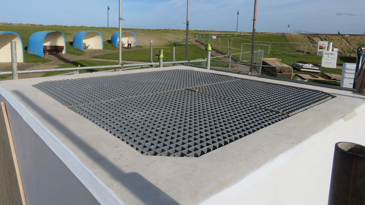
The adjacent access chamber, Chamber A on the IDB pipeline, wall height was increased by casting an additional 1m concrete wall to provide the required extension above the predicted flood level. Two smaller ventilation chambers on the downstream culvert were extended using prefabricated steel vent shafts bolted to the existing chambers.
Completed chamber extensions – Courtesy of Jacobs
Conclusions
The installation of the penstock and associated chamber modifications was completed during Spring 2021. The project team undertook this project during the Covid-19 pandemic and the associated HSE requirements/challenges to travel, working practices and the supply chain. The successful completion of this project and the wider coastal protection works has allowed the Trusthorpe outfall to continue to discharge, whilst providing tidal protection during extreme tidal events in the future.
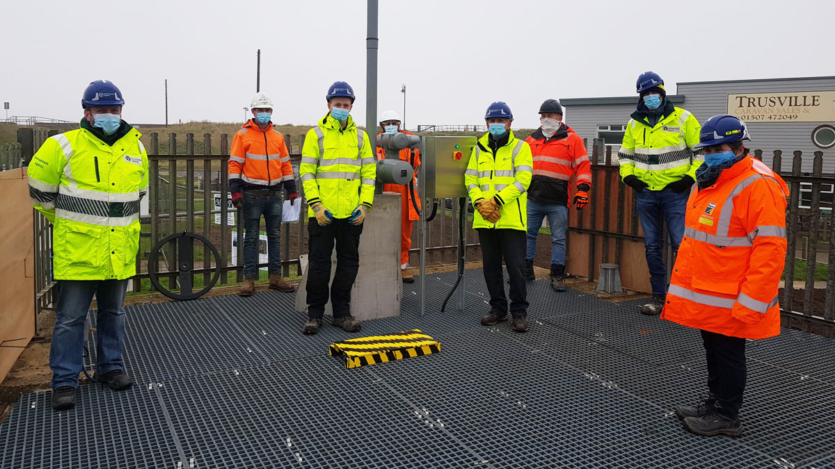
Handover – Courtesy of Jacobs