Usk Spillway Upgrade (2018)
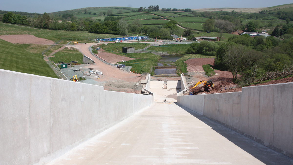
View looking down the RC chute to tumble bay and site welfare - Courtesy of Skanska UK
Usk Reservoir in Brecon is situated south east of Llandovery and approximately 5km to the west of Sennybridge. The reservoir is an existing 12.3Mm3 reservoir in the Brecon Beacons National Park in South Wales. It is impounded by a 31m high, 480m long embankment dam with a clay core, which was constructed in 1955. The reservoir has a surface area of 1.12km2 when filled to its top water level of 306.35mAOD. The reservoir is fed by both direct and indirect catchments and thereafter supplies raw water to Portis and Bryngwyn Water Treatment Works. There are no further reservoirs upstream.
The scheme
Welsh Water commissioned principal contractor Skanska UK, under the Welsh Water Capital Alliance, to carry out an extensive upgrade and refurbishments to the spillway and bridge at Usk Reservoir.
The solution was a bespoke design conceived by Mott MacDonald Bentley (MMB). Assessment reports highlighted several aspects of the reservoir and its components that would benefit from modernisation, so an improvement programme was undertaken in 2018. The work required was twofold and addressed Usk’s spillway and the refurbishment of the road bridge over the spillway.
The challenge
In 2009, an inspection of Usk Reservoir recommended that an updated flood study be undertaken for the reservoir, following completion of ongoing research into extreme rainfall. In January 2014, a high-level leak was identified at the site, located within natural ground on the right abutment below the spillway.
The leak was located away from the main dam body and did not present an immediate hazard to the integrity of the dam.
View looking up existing spillway from stilling basin Courtesy of Skanska UK
It most likely originated either from leaking joints in the spillway chute (which was spilling at the time of the incident), or from groundwater flows in the natural ground on the right abutment. The leak was probably triggered by high rainfall and reservoir levels over the previous month.
On the recommendation of an All Reservoirs Panel Engineer (ARPE), the reservoir has been held at a maximum of 1m below top water level (TWL) since that time. Pre-feasibility studies were completed in 2014 on behalf of Welsh Water, the facility’s operator, including a flood study and interim assessment of works required by Stillwater Associates Ltd, and hydraulic modelling by CRM Rainwater Drainage Consultancy Ltd (CRM). In 2016/2017 Welsh Water commissioned MMB under the AMP6 Framework to undertake a feasibility study to investigate options for upgrading the Usk spillway.
The study’s findings indicated:
- The existing overflow arrangement was under capacity, flow was thrown out of the channel by existing baffle blocks and the downstream stilling basin was largely ineffective.
- The existing foundations appeared to have deteriorated since the original spillway construction, with voids and weak zones of material evident from intrusive and non-intrusive surveys.
- The existing mass concrete spillway base slab was severely cracked.
- The existing wave wall was structurally deficient for the anticipated wave loading in a probable maximum flood (PMF) event. If the wave wall were to fail in a PMF event, the effective dam wave freeboard would be marginal.
- There was insufficient evidence to recommend replacement of the wave wall on reservoir safety grounds, but works would be required to remediate the existing wave wall, including a section of the wall adjacent to the spillway bridge, which had rotated, possibly indicating a loss of support due to erosion.
- The existing spillway bridge was in poor condition and impinges on flows over the spillway weir in a PMF event.
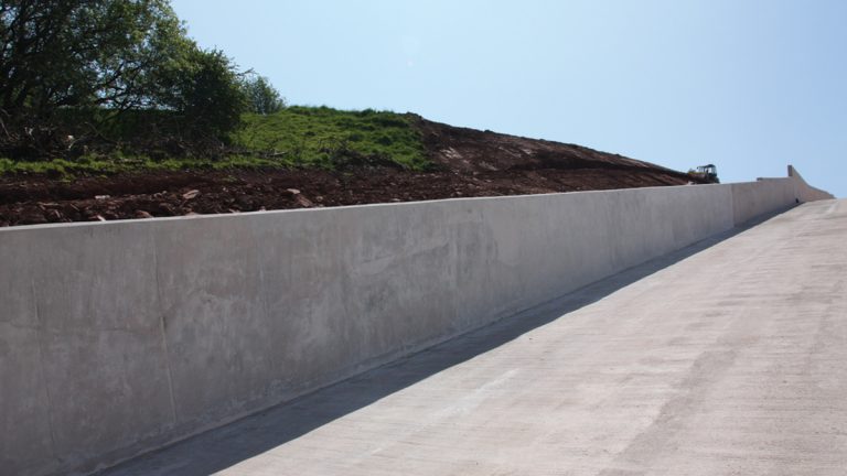
New RC chute, wall and base – Courtesy of Skanska UK
The scope of work
To address the findings of the study, the scope of work required was as follows:
- Construction of a reinforced concrete watertight spillway lining to fully contain design flows, including localised wall raising.
- Removal of the existing baffle blocks and guide wall.
- The addition of shear keys for spillway chute stability.
- Grouting works to close voids and to enhance the existing grout curtain.
- Addition back of wall drainage along the right side of the spillway chute.
- Earthworks to achieve the required finished ground profile adjacent to the spillway walls.
- Remedial/repair works to the existing wave wall and spillway approach wall.
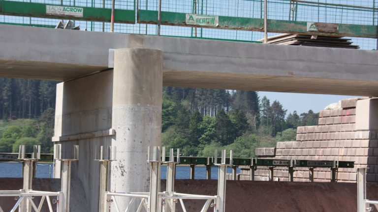
Works to replace the existing bridge deck were also included in this contract but were dealt with separately to the spillway project.
Table of designers, contractors and suppliers
- Principal contractor: Skanska UK
- Sub-contractor on the spillway works: Lewis Civil Engineering – now (Dec 2022) Envolve Infrastructure
- Feasibility study & design: Mott MacDonald Bentley
- Flood study & interim assessment: Stillwater Associates Ltd
- Hydraulic modelling: CRM Rainwater Drainage Consultancy Ltd
- Geotechnical investigation: Geotechnics Ltd
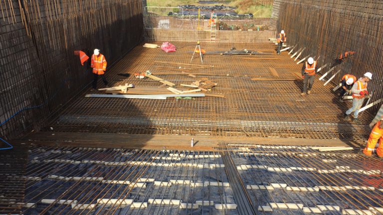
Civil works
Tumble bay: The tumble bay required contact and consolidation grouting works to fill voids and improve rock mass quality under the spillway base slab. This included gravity grouting to reinforce the connection between the concrete cut-off wall and clay core to the left of the spillway bridge, and pressure grouting of the connection between the existing concrete cut-off and rock foundation under the spillway weir and sufficient grouting to seal the grout curtain to depth.
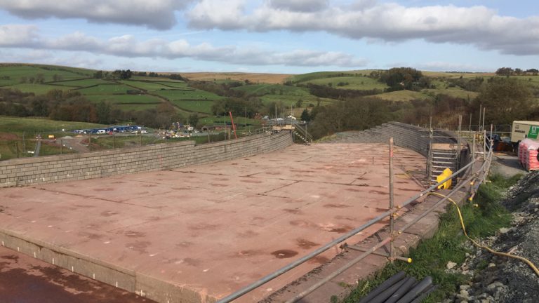
The work also included breaking out of the downstream toe of the existing weir to form a vertical construction joint with the new lining, removal of masonry facing to the existing spillway walls to create a recess for the new spillway lining and breaking out of the existing spillway base slab along the existing tumble bay walls and building up in mass concrete, to a new lower formation level for the new lining works. A reinforced concrete watertight lining (Class 1 to BS EN 1992-3:2006) to the existing tumble bay (walls and base slab) was constructed to fully contain PMF flows, including wall raising. The thickness of the new tumble bay walls is 450mm, and the base slab was thickened to 450mm.
Contact grouting of top chute and part of tumble bay – Courtesy of Skanska UK
Upper spillway: Works to the upper spillway comprised of the removal of the existing guide wall, contact grouting works to fill voids and improve near-surface rock mass quality under the spillway base slab, and grouting of the existing foundation cross-drains to prevent groundwater/seepage discharge towards the dam mitre and to prevent rock erosion by water flow. A reinforced concrete watertight lining (Class 1 to BS EN 1992-3:2006) to the existing spillway chute (walls and base slab) was constructed to fully contain PMF flows, including wall raising.
Lower spillway: Works to the lower spillway comprised removal of the existing baffle blocks and contact grouting works to fill voids and improve near-surface rock mass quality under the spillway base slab, and grouting of existing foundation cross-drains, to prevent groundwater/seepage discharge towards the dam mitre and to prevent rock erosion by water flow. In addition, dowels were installed within grout holes to connect the new and existing slabs and shear keys were installed for spillway chute stability.
Cross drains formed from no-fines concrete were installed upstream of the shear keys and associated transverse connector drains, which discharged through the existing left-hand spillway walls, and a reinforced concrete watertight lining (Class 1 to BS EN 1992-3:2006) to the existing spillway chute (walls and base slab) was constructed to fully contain PMF flows, including wall raising.
Stilling basin: Investigations to the stilling basin was undertaken to confirm the base slab thickness and foundation material, comprising of two concrete cores, excavation and sampling of the underlying material. Contact grouting works was carried out to fill voids and improve near-surface rock mass quality under the spillway base slab.
A reinforced concrete watertight lining (Class 1 to BS EN 1992-3:2006) to the existing stilling basin (walls and base slab) was constructed to effectively dissipate flows of up to 1,000-year return period, including localised wall raising.
In addition, a downstream weir was constructed, which will act as a ramp to convey higher return period floods downstream away from the dam and spillway structures. Breaking out of the upstream face of the existing downstream sill formed a vertical construction joint with the new weir.
Steel fixing in stilling basin – Courtesy of Skanska UK
Drainage
In addition to the drainage works outlined above, further drainage work comprised of the back of wall drainage installed at the base of the existing right spillway wall, which consisted of a 300mm diameter semi-perforated pipe with geotextile filter wrap and 10mm single size granular surround. This was installed in a trench of minimum 800mm width.
The base of the drainage trench was blinded and lined with concrete canvas and connected to the back of the existing structure. This lining acts to seal the interface, between the existing side wall and base, and the original rock formation level, to prevent or limit groundwater ingress to the interface, which would otherwise degrade to rock formation in the future.
The drainage starts from right wall chainage CH+10. Rodding points were constructed at 25m spacing, with the first rodding point at the upstream end of the drain. Inspection chambers were installed at 50m spacing along the length of the drain. A monitoring chamber was installed at the downstream end of the drain, adjacent to the stilling basin, into which the drainage pipe will discharge.
New RC bridge at dam crest under construction – Courtesy of Skanska UK
There was also further remedial works to the existing wave wall and left spillway approach wall. The works was programmed to take place during favourable weather conditions and over as short a duration as is practicable.
Work commenced in April 2017, for 18 months. Skanska was the principal contractor, with Lewis Civil Engineering sub-contracted to carry out the spillway works. Where walls were demolished and reconstructed on site, every effort was made to reuse the existing masonry blocks. Where new blocks were required, these were cast based on the masonry block dimensions.
Spillway bridge works
Works to replace the existing bridge deck were also included in this contract. This included the demolition of the existing bridge deck, to be replaced with a new structure of minimum five tonne capacity, with a raised soffit level giving 300mm freeboard above PMF peak still water flood level (PSWFL).
The existing spillway weir, bridge piers and bridge abutments were retained with any required remedial work carried out.
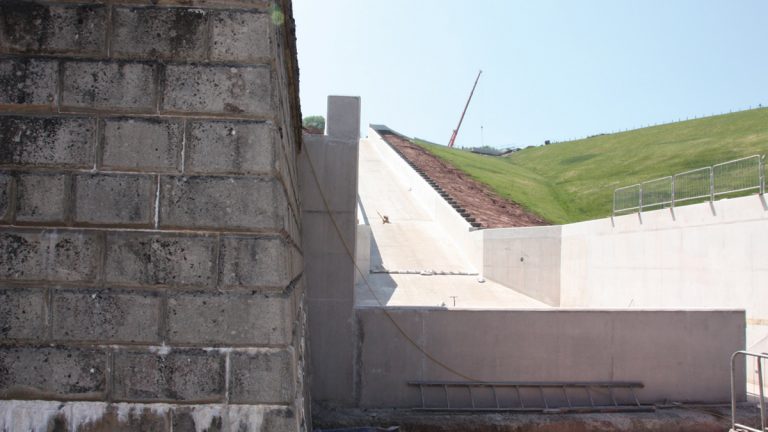
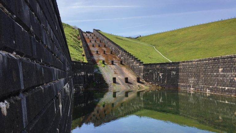
Completed view of new RC spillway – Courtesy of Skanska UK
Progress
As of June 2018, the concreting works are substantially complete with re-profiling of the spillway crest and approach channel ongoing. Demobilisation is planned for mid-August 2018.