
Warland Impounding Reservoir (2019)
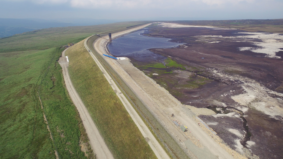
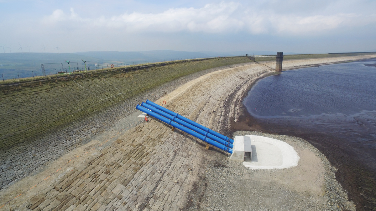
Warland Reservoir drawn down by 8m, and upstream pipe work installed - Courtesy of MMB
Warland Impounding Reservoir (IR) is situated on the western slope of Blake Moor, above Littleborough, Lancashire. The reservoir was originally constructed around 1857 by the Rochdale Canal Company to maintain water levels in the Rochdale canal, and was considered to be one of the largest dams in England at the time. It has a 1500m long, 20m high embankment made of homogenous earth fill. Warland IR is a Category A reservoir as defined in the Reservoirs Act 1975.
Project drivers
There were 2 main project drivers:
- Measures in the interest of reservoir safety: The existing scour (and compensation) main that runs through the embankment could only achieve a drawdown rate of 100mm/day. This was considered inadequate in an emergency situation, and so recommendations were made to increase this to 1m/day.
- Portfolio risk assessment: United Utilities carried out a targeted risk reduction strategy, termed Portfolio Risk Assessment (PRA), which when used in conjunction with a ‘toolbox’ assessment, highlights key risks to be addressed to reduce the probability of failure of the embankment to an acceptable level. Due to the presence of a single pipe through the embankment, and the nature of the embankment material, the risk of failure due to internal erosion mechanisms was high. The solutions identified in the study included:
- Provision of a grout collar around the existing scour pipe.
- Infilling of the existing scour tunnel (culvert).
- Automatic flow measurement of the flow over the existing v-notch weirs on the toe drains and facilities to transfer the flow measurements in real time via telemetry.
Challenges
There were numerous challenges and constraints on the project, not least the location – a remote site at 375m above sea level. The reservoir operator had decades of experience at the site, and noted that the reservoir regularly froze in winter (temperatures below -20°C had been recorded) and the 3km long access track would be impassable. Other challenges included:
- Drawdown: If work was required in the reservoir basin, the reservoir would have to be drawn down by at least 8m. In such a location, with very little means of controlling water level, this was a key challenge.
- SSSI/blanket bog: The reservoir was surrounded by SSSI, designated for the blanket bog.
- Site access: The access was a 3km narrow track to the site, in poor condition.
- Silt: The reservoir basin was known to contain large amounts of silt.
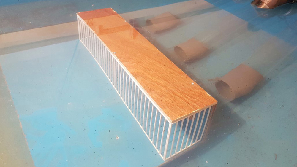
Physical model of upsteam siphon inlet and screen – Courtesy of MMB
Optioneering
Early optioneering of the drawdown requirements identified siphon pipes through the dam crest as the only viable option to achieve the required capacity. There were numerous solutions to the arrangement, which considered the following factors:
- Alignment: The alignment needed to be optimised as to offer the best value hydraulic design for the drawdown capacity whilst minimising the length of temporary access works in the reservoir basin, and not interfering with the existing scour system.
- Level of the siphon crest level: A lower siphon crest level, relative to reservoir top water level, would improve the siphon hydraulics, but would mean an upstream guard valve may have been required. Consideration also had to be given to future settlement of the embankment. An allowance for 60 years of future settlement was included in the design constraints.
- Critical (minimum) inlet submergence: This was identified as key to the hydraulic design and so physical modelling of the inlet was required.
- Discharge location: Location of the discharge point near to the toe of the embankment, or further down the clough where the spillway discharged.
- Valve arrangement: Upstream control was required in some configurations depending on the method of priming the siphon. Submerged discharge valves were considered at the downstream end.
Transition chamber and 3 siphon pipes discharging at design flow of 3.6m3/s – Courtesy of MMB
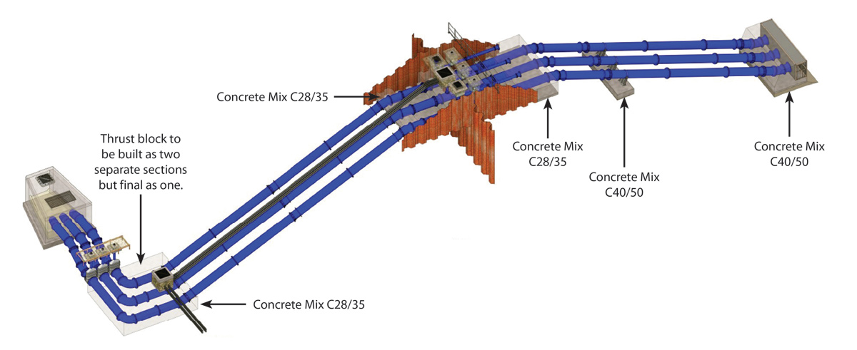
Several combinations of siphon pipe sizes and materials were considered. The preferred option was for 3 (No.) DN600 ductile iron pipes through the dam crest to act as a siphon. These would be located midway between the valve-tower and the eastern abutment on the part of the dam that gave the shortest linear distance of siphon whilst still achieving the required upstream submergence depth. The revised position approximately halved the amount of temporary access road required to construct the access ramp into the reservoir basin. Three pipes were preferred over one to significantly reduce the scale of temporary works from lifting. The arrangement also enables each pipe to be individually tested in a controlled manner and reducing the risk of downstream erosion due to high flows. In the event of a failure on one of the 3 (No.) siphon lines, the system offers redundancy, still allowing for a significant drawdown to be undertaken.
A transition chamber at the downstream end of the siphon would combine the flows form the 3 pipes into one single DN150 concrete pipe. This would run under the access track near the toe of the dam, discharging into a chamber at the toe at the start of the clough.
With the siphon pipes located above top water level, the risk of leakage through the embankment (around the pipes) would be eliminated. However, this meant the maximum level the siphons could operate was around -5m below top water level. Although the reservoir catchment was not forested, there remained a risk of blockage of the siphons from floating debris. A screen would be required over the inlets, which would also prevent unauthorised access to the pipes if the reservoir was ever drawn down below the inlet level in the future.
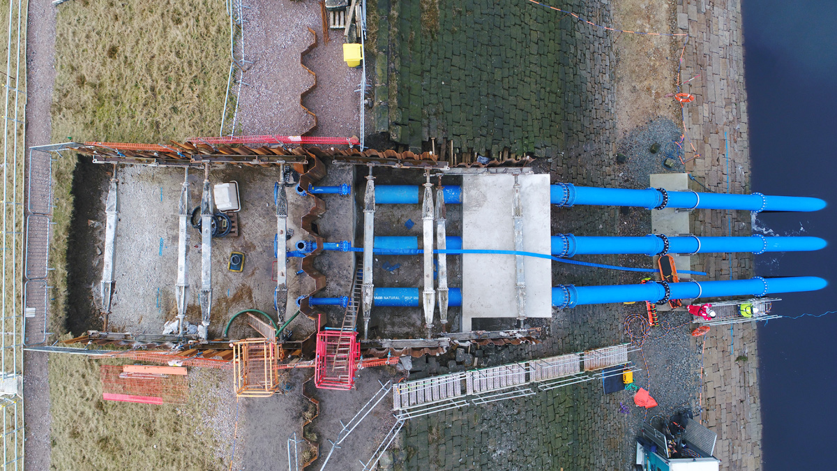
Aerial view of siphon arrangement at the embankment crest – Courtesy of MMB
Design and construction
Physical hydraulic modelling was selected as a means of optimising the design of 3 key elements of the design:
- The inlet: To achieve the shallowest depth whilst preventing submergence (air being sucked into the siphon.
- The transition chamber: To minimise size the chamber required to combine flow from 3 pipes into one.
- The discharge chamber: To still the flow down to approximately 1m/s, to prevent erosion of the downstream watercourse.
The physical modelling was able to reduce the size of the inlet chamber by 50%. Testing was carried out at various flows (replicating the flow as water level dropped in the reservoir) to determine the critical submergence at each flow rate, and thus ensure that this was in all cases less than the actual water depth above the inlet in that operating condition. The optimal design solution was found to be a 150mm spacing bar screen with a solid top, 5.1m wide, 1.6m tall, and 1.0m wide.
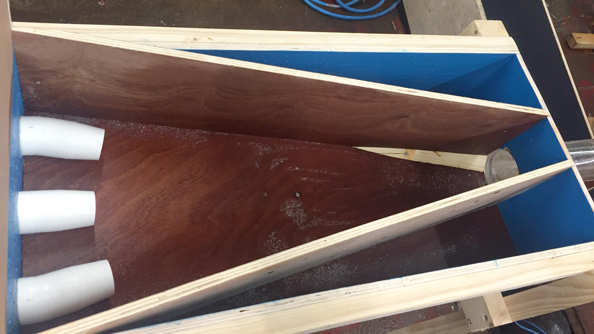
The modelling also optimised the transition chamber to a V-shaped structure. They key challenge was to try and accelerate the flows out of the three siphon pipes as they entered the larger single pipe; termed the ‘gravity’ pipe as the flow continued under free discharge, as opposed to being part of the siphon. To increase velocity and aid flow into the lower pipe, the three 600mm siphon pipes were fitted with 600mm to 500mm tapering nozzles, and the outer two pipes angles by 11.25°.
Test flows in transition chamber – Courtesy of MMB
To ensure a smooth transition into the circular section at the end, trapezoidal benching was installed along each wall, starting 3.6m from the inlet to the DN1050 pipe. Flow in the chamber was fairly smooth, with flow in the lower pipe undulating, but free from the pipe soffit at the design flow of 3.6m3/s.
The flow velocity entering the stilling chamber at full flow was approximately 7m/s. To reduce this velocity and prevent erosion downstream the proposed solution was a 7m long, 5.25m wide, 4m deep stilling basin with 2m high end cill, and horizontal baffle wall.
Construction of the project commenced in 2017 and began with significant works required to upgrade the existing 3km access track to the reservoir. This included temporary propping of a bywash channel, a new temporary crossing of the channel, widening and strengthening works to allow construction plant to access the site. The reservoir was drawn down by 8m to facilitate the construction of the upstream section of the siphons. The inlet works were undertaken first, and once installed, the reservoir was allowed to partially re-fill. To pressure test the pipes a blank plate was left on the end of each pipe, and this was removed by divers following a successful test.
There were significant concerns about embankment stability, given that a large proportion of the embankment was constructed from peat, an amount of which had been added as part of the stability works in 1923. To improve the ground conditions, the area at the toe of the embankment, where the transition chamber was constructed, has to be artificially raised with granular fill to allow sheet piles to be installed to form a stable excavation.
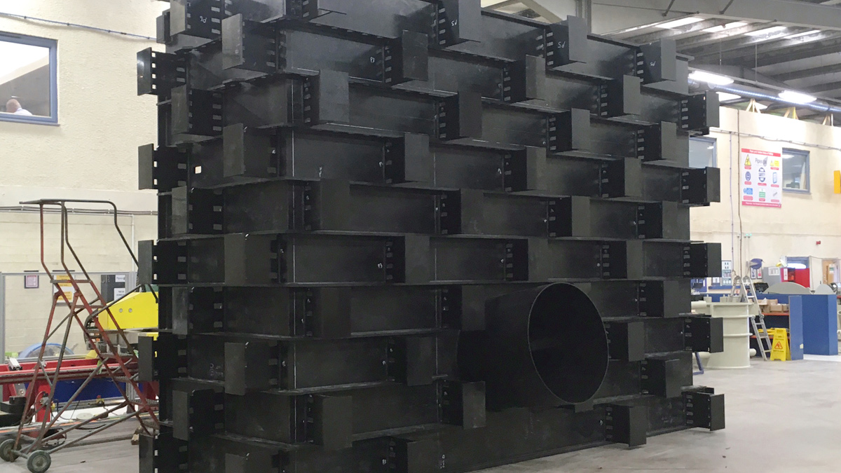
Half of the PIPEX px stilling basin ready for delivery to site – Courtesy MMB
When the reservoir was drawn down for installation of the upstream section of the siphons, there was a significant concern about a deterioration of water quality discharged downstream. The team developed a silt monitoring plan with the Environment Agency (EA) officer, including trigger points with agreed actions. Temporary pipework modifications were made in the catchment to blend the discharge waters with a neighbouring reservoir to reduce turbidity.
The grout collar around the existing tunnel was required to reduce the risk of loss of embankment fines along the outside of the tunnel. Works began with the drilling of the boreholes to install grouting lances. The drilling rig was positioned on the embankment crest and boreholes inclined 17° angle. Initially, the drilling was carried out using 80mm diameter augers. This was to remove the risk of drilling through the tunnel and jeopardising the integrity of the raw water main within the tunnel. Due to the frequent presence of obstructions in the embankment fill comprising cobbles and boulders (which the auger could not drill through), the method had to be abandoned.
Upstream pipework and inlet screen constructed – Courtesy of MMB
The alternative drilling technique comprised rotary percussive drilling (70mm diameter) using compressed air flush. Augers were used up to the point an obstruction was encountered and then the borehole was advanced to target depths using rotary percussive. This method was successfully implemented on the downstream row of boreholes.
Grout was injected from the crest of the embankment. The solution was designed by the sub-contractor and consisted of a two-part resin; Resin 1945 and hardener, Ureteck Liquid Hardener 10. The expansion of the material was achieved by the chemical reaction at the point of injection between the resin and the hardener. The mixture was designed to allow for the travel time between the crest and the injection point in the embankment. The sub-contractor utilised a grout design that was able to achieve a 1.5m expansion bulb, from the point of injection, in every direction. Confirmation that the grouting was successful was confirmed by the observed ingress of grout into the tunnel.
The infill of the tunnel was carried out after the collar grouting. A total of 262kg of material was injected into the void. This consisted of a polymerised URETEK 2640 resin. Upon completion of the infill works, the tunnel portal was clad with engineering bricks.
Warland Impounding Reservoir: Supply chain/key participants
- Project delivery: MMB
- Pre-fabricated chamber: PIPEX px
- Physical hydraulic modelling: CRM Rainwater Drainage Consultancy Ltd
- Grouting of embankment and infill of tunnel: Geobear Ltd
- Level instruments and transmitters: Technolog Ltd
Innovation & digital engineering
The project was delivered in line with BIM Level 2 processes. The client’s Common Data Environment (CDE) was used for the production, review, and publication of all engineering deliverables. 3D modelling was essential for carrying out buildability reviews and allowed several areas of the design to be value engineered, such as the valve arrangement on the embankment crest which was significantly simplified from a large chamber to individual valve boxes on each siphon pipe.
The scope of work at Warland IR included remote monitoring of the toe drainage, as a means of early detection of leakage through the dam. There are a series of existing manholes on the toe drainage, with existing V-notch weirs on them. These were read manually every week.
To achieve the required level of risk reduction as part of the PRA and Seepage Toolbox study, the drainage required more frequent monitoring, coupled with an ability to alarm remotely if the flow through the drainage increased above a set level (indicating leakage of the embankment). The alarm would trigger a response, and the water level in the reservoir could be lowered quickly using the siphons. The original solution was to install a new power supply to site. However, Warland IR is extremely remote, and the cost of a new supply was of the order of £1.5m. The innovative solution was to provide Technolog Cello units.
3D model of the siphon system and temporary works on the dam crest – Courtesy of MMB
The Cello units are battery operated and use a 4G network to transmit a signal to Technolog’s Watercore, which then connects to UU’s telemetry/ICC. Similar units are used on CSOs, but they have never been used on an impounding reservoir for this type of application. Not only did this save approximately £1,000 in operational costs, but it also provides a safer way of reading flows from the 4m deep chambers.
To link the alarm system for increased flows in the toe drains with reservoir level, an ultrasonic level sensor had to be installed on the existing valve tower to record the variations in the reservoir levels. A survey of the valve tower and area around it was required, but there were steep slopes and working at height over water. A full survey of the valve tower and adjacent area was carried out using a drone in approximately 30 minutes. The photos from the survey were used with photogrammetry software to produce a 3D model of the area. This was exported into Autodesk Revit as a point cloud and used to develop the design of the ultrasonic sensor and required cabling and attachments.
There was a desire from the project team to build off-site as much as possible, not only because of the safety benefits, but because of the remoteness of the site, susceptibility to harsh weather, and poor ground with a large presence of peat. For the stilling basin, PIPEX px were commissioned to design and fabricate the chamber. An in situ concrete base was constructed, then the chamber was delivered to site in two pieces, with reinforcement already installed between the two pieces of HDPE plastic walls. In situ concrete was then poured to infill the walls and roof.
The control unit for the siphon system, including the vacuum pumps and the diesel generator, are housed in two separate kiosks at the toe of the embankment.
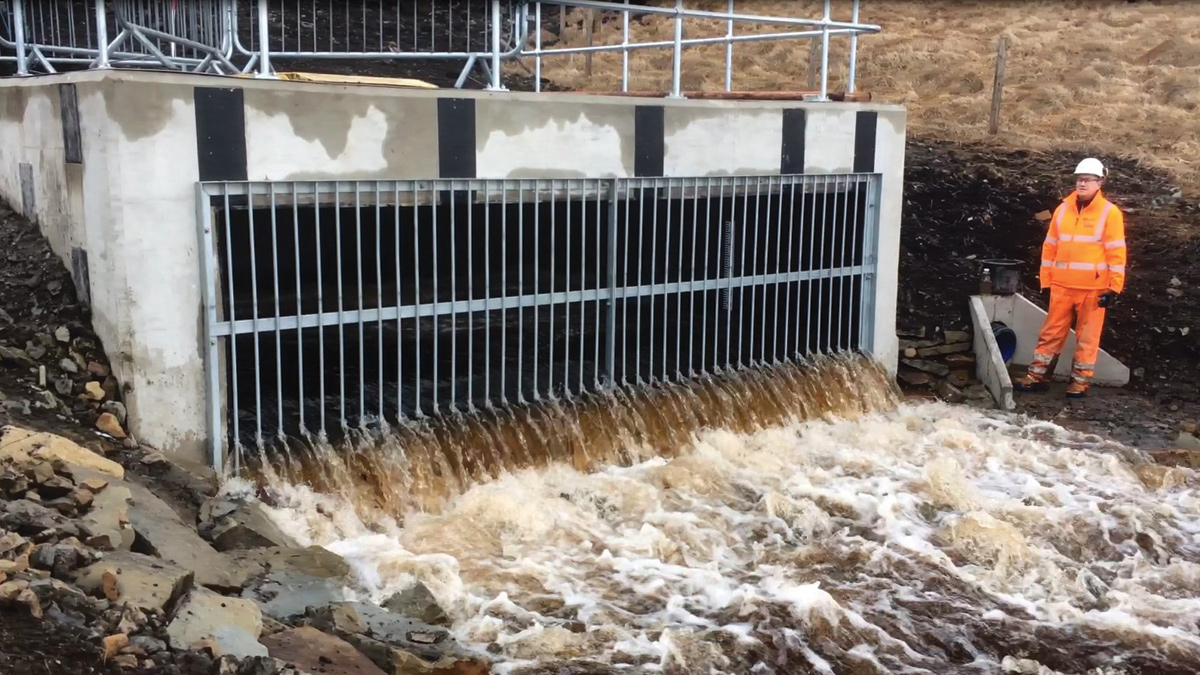
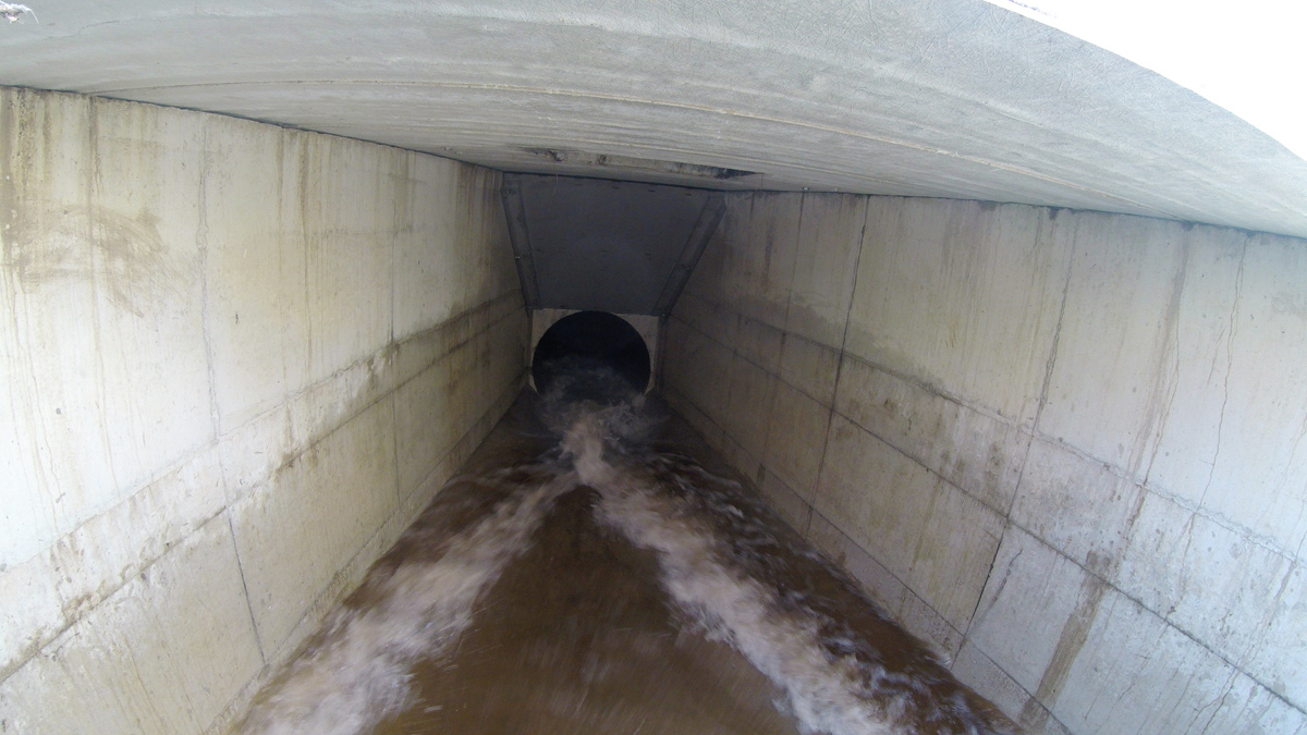
Siphon test flows leaving stilling chamber – Courtesy of MMB
Operation
Suction priming was the preferred method selected and was designed to fully prime the system from empty within two hours. The priming system is powered by an on-site generator which supplies three priming pumps. The siphons are controlled by 3 (No.) gate valves located at the toe of the embankment, just upstream of the transition chamber.
No upstream control valves are required within the reservoir basin, which significantly reduces the operational risk. Air valves (small diameter gate valves) located at the crest allow air to be introduced into the siphon crest ‘breaking’ the siphon during discharge.
Completion testing and the witness test with the Qualified Civil Engineer (appointed under the Reservoirs Act 1975) took place over three days in spring 2018. On all occasions, the three lines were primed in a combined time of less than the target of 2 hours. In addition, the flow measurements at the stilling basin weir met the calculated flow required to achieve the drawdown of 1m/day.