
Tideway West – Barn Elms CSO Connection Tunnel (2023)
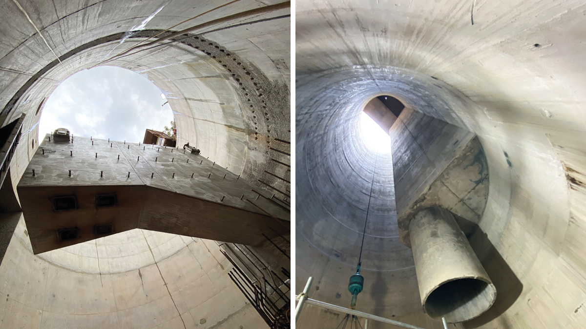
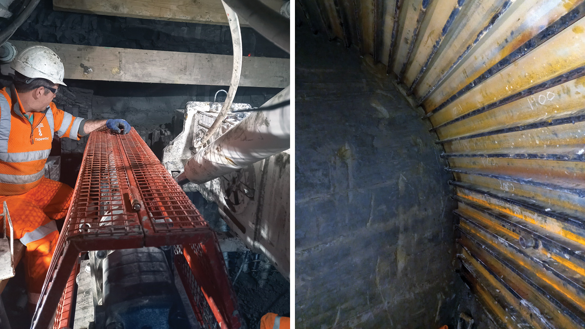
(left) Vortex generator (a 6t stainless steel pipe adaptor) and (right) view from the base of the shaft - Courtesy of Barhale
The Thames Tideway Tunnel Project is a 25 km (16 mi) combined sewer under construction under the tidal section of the River Thames as it runs through London. It will significantly increase the capacity of London’s sewerage system (large sections of which were built in the 19th century), and be able to capture, store and convey almost all the raw sewage and rainwater that currently overflows into the Thames Estuary. The Thames Tideway Tunnel will connect 34 of the capital’s most polluting combined sewer overflows (CSOs), transferring the foul water to the Lee Tunnel for onward delivery to Beckton STW. The completion of the Thames Tideway Tunnel scheme, currently anticipated for 2025, will significantly improve water quality capturing more than 95% of the spills that currently enter the river to the benefit of London’s almost 9 million residents.
Project summary and location
As part of works on the west section of the Thames Tideway Tunnel scheme, Barhale was contracted by the BAM Nuttall Morgan Sindall Balfour Beatty (BMB) joint venture, to construct a series of complex underground structures that would intercept the sewage overflows from the West Putney Storm Relief Sewer for transfer to the main Tideway tunnel beneath the River Thames.
The site was located in Richmond, on the south side of the River Thames between Hammersmith Bridge and Putney Bridge, and adjacent to Barn Elms Sports Centre.
Scope of work
The scope of works included the construction of a 35m deep x 6m internal diameter drop shaft and a 215m long x 3m outside diameter connection tunnel. Surface level works include 6m deep reinforced concrete (RC) interception chambers, an RC culvert and an RC MEICA building, comprising an electrical intake room, telemetry room and control room for system alarms and automated actuated valves installed by the lead contractor.
Barhale also built an 800m long, 4m wide access road, and installed additional sections to address Environment Agency and local authority requirements relating to existing flood defences and protected trees in the proximity of the works.
The drop shaft’s construction required initial and primary spray concrete lining (SCL), with a secondary cast-in-place concrete lining to encase a new 26m long x 90mm diameter stainless steel vortex drop tube pipe. The shaft was constructed using steel fibre reinforced concrete, applied by an Oruga robotic spray machine as the excavation progressed in 1.2m increments.
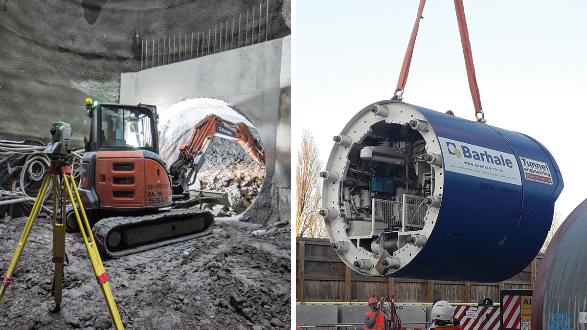
(left) Excavation at the shaft base and (right) 2.5m ID tunnel excavator machine (TEM) being lowered into drive shaft – Courtesy of Barhale
Detailed mapping and innovative control
Unlike most other Tideway sites, Barn Elms is comparatively small and the connection tunnel drive through the London Clay Formation had to be delivered from a relatively narrow 6m diameter shaft. More than two months were spent preparing a plan and mapping out the tunnel drive route to ensure the team did not encounter any unexpected problems during the drive.
The requirement was that the tunnel excavator machine (TEM), which needed to be compatible with 3m diameter jacking pipes, would not have been recoverable from a standard reception shaft as the connection to the main tunnel was right under the River Thames. To address this challenge, Barhale collaborated closely with Tunnel Engineering Services (UK) Ltd to design and construct a TEM whose internal parts could be dismantled, removed and re-used after the project’s completion.
The new TEM was brought to site without any engineering guiding systems so the team also needed to address the question of control.
Drawing on Barhale’s extensive mining experience, traditional and digital equipment was installed on the machine to control the steer, roll and the pitching degree. Digital pressure gauges were also fitted to ensure that the limit on the jacking pressure was not exceeded.
The TEM was steered by four pairs of hydraulic cylinders located between the hood and the machine body. Using information available on the geometry of the TEM and the jacking pipes, plus knowledge of the maximum allowable joint deflection of the jacking pipes, it was calculated that the steering cylinder should not be opened more than 20mm when all other cylinders are fully retracted.
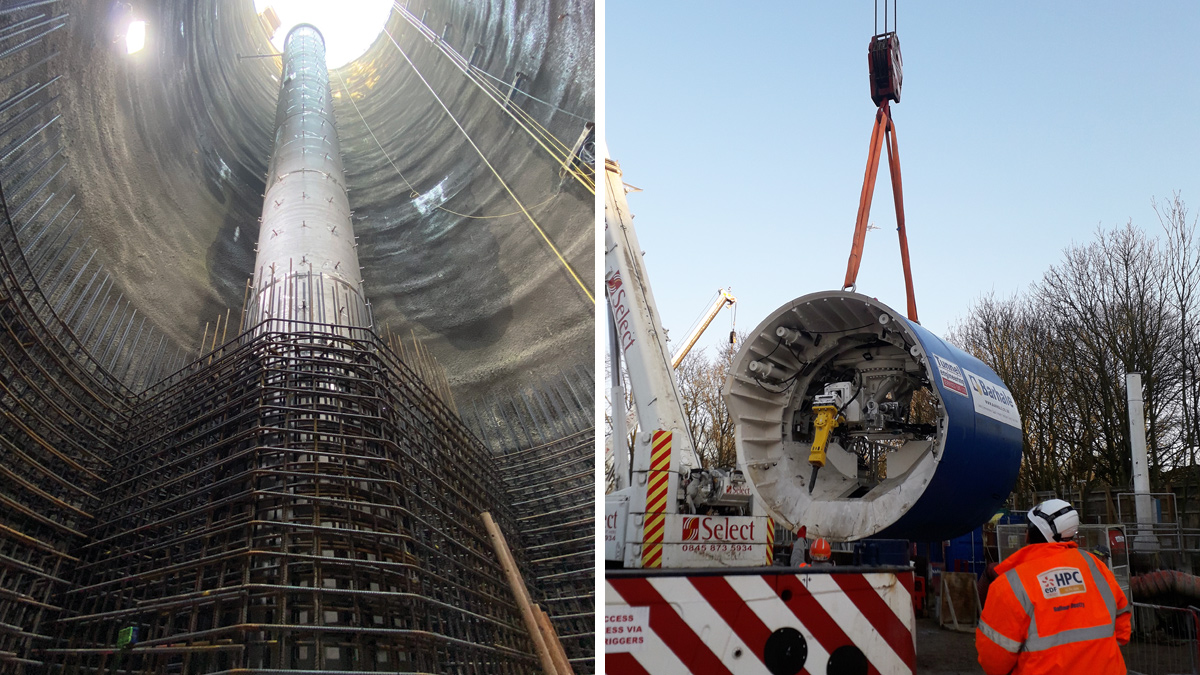
(left) Barn Elms shaft under construction and (right) the 2.5m ID tunnel excavator machine (TEM) being lowered into drive shaft – Courtesy of Barhale
The TEM roll represents the machine’s rotation about its central axis and there was a continuous tendency to clockwise or anti-clockwise spin. To overcome the issue, inclinometers and laser targets were installed within the machine and used for base readings for roll calculation.
Installing the bespoke guidance equipment, and in-detail mapping of every stage of the drive, ensured that the TEM was able to operate effectively and carry out the pipe jack successfully.
A further challenge was the safe handling and maintenance of the 14 tonne, 3m diameter precast concrete jacking pipes. To address the issue, Barhale purchased a 20 tonne SWL welding roller to be used as a base stand so that the pipes could be rotated 360°. This solution enabled the team to inspect each pipe thoroughly without the need for access equipment and working at height.
It also brought a huge benefit in the preparation of the inter-jack stations. Using this system, the inter-jack hydraulic cylinders could be installed around the circumference of the jacking pipes by the fitters from standing position.
Overall, the use of the welding rollers saved the Barhale team time, eliminated the risk of working at heights, and reduced the number of lifting operations. This idea was nominated for a Tideway RightWay award.
Barn Elms CSO Connection Tunnel: Supply chain – key participants
- Main designer & contractor: BMB JV
- Delivery contractor: Barhale
- Reinforced concrete works/formwork: Flatley Construction
- Secondary lining shuttering: EFCO UK
- Spray concrete lining: Shotcrete Services Ltd
- Steel fibre reinforced concrete: CEMEX UK
- Tunnel boring machine: Tunnel Engineering Services (UK) Ltd
- Precast jacking pipe segments: Macrete (Ireland) Ltd
- Stainless steel vortex generator: BMB JV
- Stainless steel vortex drop tube pipe: BMB JV
- Precast concrete cover slabs/planks: Barhale
- Ventilation/odour control: Specialist Plant Associates
- Demolition robot: Brokk Global
- Robotic concrete spray machine: MEYCO Oruga
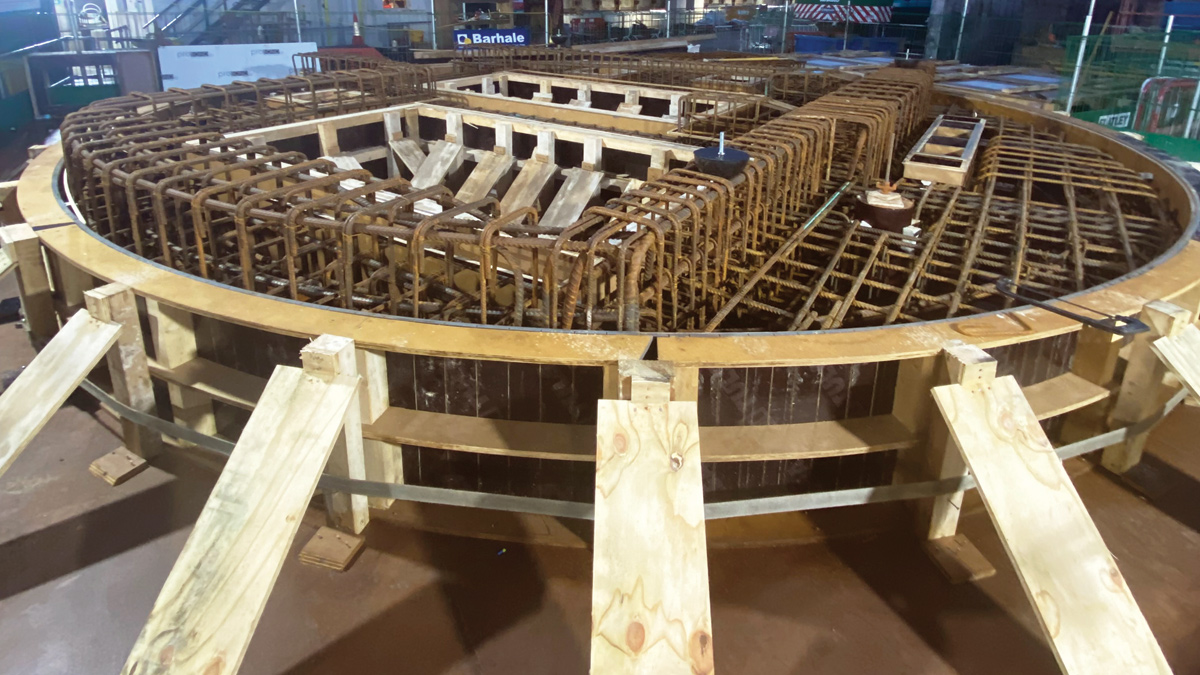
Shaft cover slab under construction – Courtesy of Barhale
Challenging tunnel construction
The tunnel was constructed using a pipe jacking technique in which the TEM was attached to a muck conveyor. The pipes were jacked continuously from the drive shaft as the excavation of the tunnel face progressed.
This was a relatively large pipe and the team encountered a significant challenge about 30m into the pipe jack when small cracks were identified in nine of the eleven pipes that had been installed. The defective sections needed to be replaced. The two un-cracked pipe sections were at the rear of the pipe jack and had not entered the ground so were relatively easily removed, however, it remained necessary to remove the other nine sections. This would only be possible by breaking out the pipe sections.
A recovery strategy was developed which was centred on the fabrication of a bespoke shield which could be jacked along the line of the existing cracked pipes. A special hood was devised which, as the shield moved forward, would pass above the damaged sections providing support to the tunnel roof. It would protect the workforce and equipment and allow work on the removal of the pipe sections to begin.
A further consideration was that damage to the original concrete lead pipe meant it could no longer be used. It would have taken too long to recast a new concrete section so the steel shield was also designed so that it could be jacked in and used as a replacement.
To start the recovery, each of the individual damaged concrete pipe sections was circumferentially and longitudinally cut into small sections. The breaking out was carried out by a Brokk demolition robot which moved down the existing pipework ahead of the shield.
(left) The probe drill in use, forward probing of the tunnel face before full excavation as part of the WPP and (right) temporary support from within the sacrificial outer skin of the TEM once the tunnel drive was completed – Courtesy of Barhale
Once each concrete section had been broken out, the Barhale team could move in and pull the concrete from the invert back to the pit bottom for removal. Positioning the Brokk in advance of the shield meant that the removal of the material was not impeded.
Proceeding section by section, it took two and a half weeks to reach the TEM. Removal of the damaged lead pipe revealed that, under the pressure of sitting stationary in the ground for five months while the recovery strategy was devised and implemented, the tail skin of the machine had deformed more than anticipated.
By restarting and moving the TEM followed by the recovery shield forward into virgin ground, the Barhale team was able to relieve the pressure on the tail skin. This permitted the removal of the hood and the docking of the steel lead pipe after which the drive could be restarted.
Replacing the damaged reinforced concrete pipes created quite a challenge, but with the support of the project team, a pioneering solution to change the cracked pipes was developed. The recovery shield that Barhale developed not only enabled the damaged tunnel to be replaced but also enabled access to the TEM face where repairs and enhancements had to be conducted. Additionally, the purpose made tunnel shield was designed to allow complete dismantling upon completion of the tunnel drive, allowing the final connection to the main tunnel.
Secondary lining
The pipe jack was followed by a cast-in-place secondary liner to the pipe jack tunnel. Barhale worked with suppliers to design and procure an automated tunnel liner system that significantly improved the quality of the tunnel secondary liner.
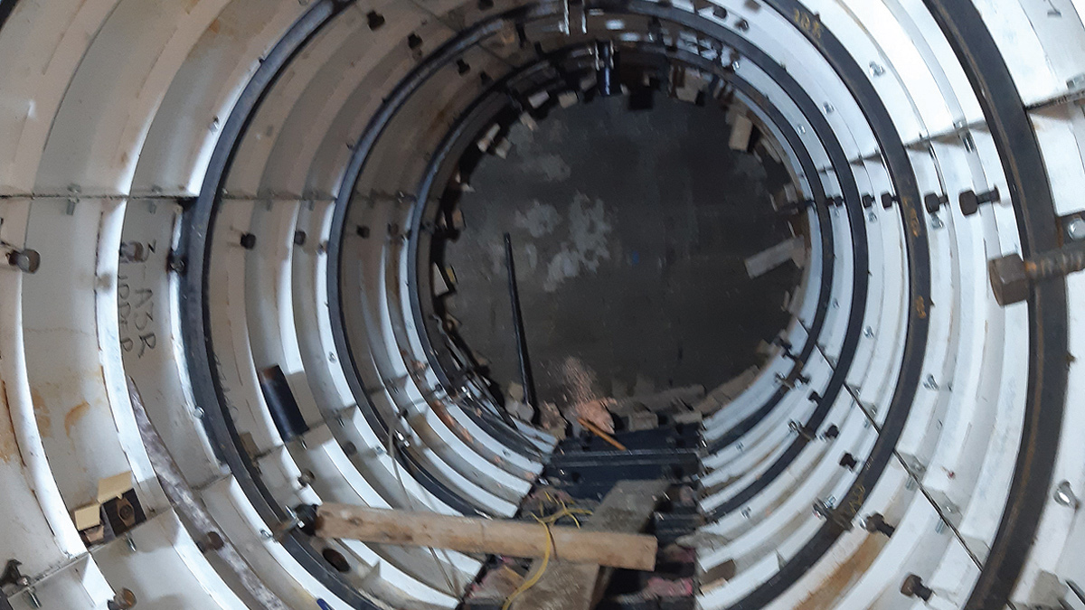
Secondary lining shutter in place within the sacrificial TEM outer skin at the junction of the main Tideway central tunnel – Courtesy of Barhale
This consisted of a specialist automated tunnel formwork system that would ensure the tunnel secondary lining was constructed efficiently by pouring each section in one pass. This improved quality by reducing the number of construction joints compared to more traditional methods. As the equipment is fully automated, the hydraulic stop ends ensure a robust seal when pumping concrete. A mechanical travel system enabled quick set-up for each subsequent pour with minimal resources and it removed the need to manually strike and reconstruct formwork for each section of the lining.
Designed for life
The client required 120-year design life for the precast concrete jacking pipes. To achieve this, Barhale’s engineers worked closely with the client’s designer, materials engineers and precast experts to develop a detailed quality assurance system that included concrete mix trials and quality audits at our supplier’s facility.
In addition, Barhale implemented a stringent quality control regime that covered the pre- and post-pouring of the pipes, curing, handling and transportation of the pipes.
Carrying out the works required excellent stakeholder management throughout. Heavy plant deliveries were required to fall within stringent Tideway traffic management plans.
Thorough planning and consultation with the supply chain, client representatives and third party stakeholders were also key for excellent HSE performance. Barhale supported BMB with meetings and workshops with asset protection teams, Thames Water, the Environmental Agency, the local authority and local council groups.
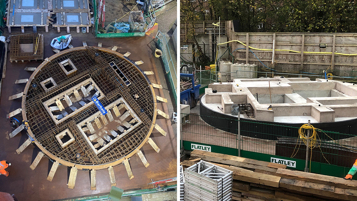
Shaft cover slab under construction – Courtesy of Barhale
Peter Leyton, Construction Director for the BAM Nuttall Morgan Sindall Balfour Beatty JV, praised the Barhale team for its hard work and effort in getting the TEM to the main tunnel connection:
“The resolution in the team, to come from where we were earlier and then to work through all the issues that were put in the way, is a huge testament. Also, the control of the movement in the main tunnel has been excellent and a great reflection on the efforts put in by all of the team.”