Billericay, Danbury & Hollingsworth Road Water Towers (2020)

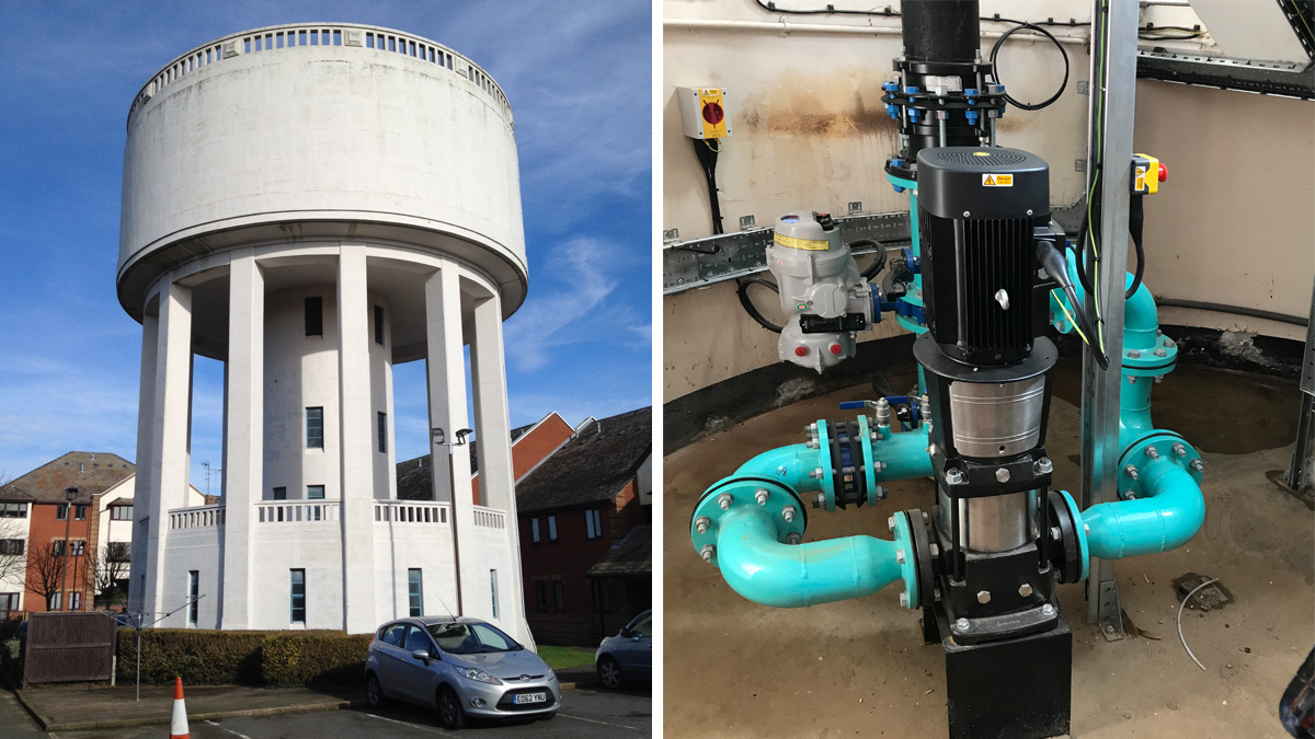
(Left) Billericay Water Tower and (right) the new booster pump system - Courtesy of Essex & Suffolk Water
The low-pressure standard (formerly called DG2) is defined by Ofwat as a pressure of less than 10 metres at a flow of 9 litres per minute when measured on the customer side of the water company stop tap. Any properties in breach of this threshold are recorded on the low pressure register and the number at year end is reported to Ofwat. Historically poor performance in the field of low pressure has had a reputational impact but more recently it now has financial penalties since the introduction of Outcome Delivery Incentives (ODI). Equally, good performance in this area attracts financial reward. At NWG, monitoring of low pressure takes place in the form of a comprehensive pressure monitoring system with pressure loggers at thousands of points throughout its network. This system enables NWG to correctly identify the properties which receive pressure below the standard and consequently it enables the introduction of pressure improvement schemes. These schemes are generally in the form of new mains, new booster stations or network rezones.
The issue
Northumbrian Water Group (NWG) supplies water and sewerage services to 1.3 million properties in the north-east of England, trading as Northumbrian Water. NWG also operate in the south-east of England trading as Essex and Suffolk Water supplying water only services to 794,000 properties.
Water demand is the highest in the summer months which often coincides with when the lowest water pressures are witnessed in the network. Following the summer of 2019 and subsequent analysis of the pressure monitoring systems, 3 zones fed by water towers during the night-time were identified as suffering from inadequate water pressure. The 3 zones were supplied by the Billericay Tower and Danbury Tower in Essex, and the Hollingsworth Road Tower in Suffolk. These three sites are the topic of this case study.
All 3 zones are supported by existing booster pumps on variable speed drives. The current control philosophy involves switching the booster pumps off at night to facilitate the turnover of a static volume of water in the towers. This arrangement maintains pristine water quality within the tower. However, during this period the 3 zones rely on a gravity feed from the tower which cannot maintain network pressure above the standard. In total, 865 properties were identified as suffering from poor pressure as a result of switching the existing booster pumps off. These properties would be reported against the end of year target on 31 March 2020. As a result, the project team had 4 months to design, develop and implement a solution at all 3 sites. Failure to do so would mean NWG would fail its target for low pressure and, due to the large number of properties failing the pressure standard, would be subject to a £16m financial penalty.

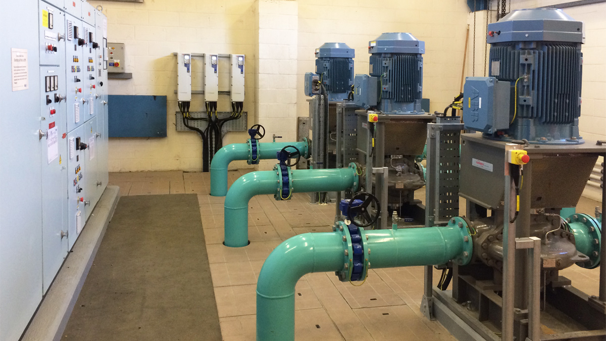
Billericay existing booster pump station – Courtesy of Essex & Suffolk Water
Solutions considered
A number of discussions were held between the key stakeholders in the business and our external supply chain partner Integrated Water Services (IWS) on how properties on the low-pressure register could be removed within time and cost constraints. One option debated included removing the towers from supply altogether and operating entirely on the existing booster pumps. This option wasn’t favoured by stakeholders due to the loss of valuable storage, particularly in the event of a power failure or pump breakdown, since these structures offer an added layer of resilience within the distribution network.
A second option involved the installation of a booster pump at the tower outlet in order to boost night flows into supply. Under this configuration the existing booster pumps would continue to switch off at night with the new tower pump responsible for maintaining network pressure and flow. Alternatively, there was an option to run entirely on the existing booster pumps and then boost tower flows into demand during peak periods. Under this configuration, the existing booster pumps would operate 24/7 and ‘back off’ for a number of hours to accommodate the additional tower pressure and flow.
Final solution
A more defined engineering solution was developed in order to allow NWG to retain the tower structures for network resilience. The solution implemented for each tower involved the installation of a new booster pump at the tower outlet to boost flows to meet the required pressure standards. The new tower booster pump operates alongside the existing booster pumps, albeit with a slightly modified configuration at both the Essex sites and the Suffolk site.
At Billericay and Danbury, the existing booster pumps now operate 24/7 and the installation of the new booster pump on the tower outlets operate for a number of hours during peak demand to facilitate the turnover of water in the tower. In comparison, at Hollingsworth Road the existing booster pumps continue to switch off at night and the new tower booster pump operates to maintain supply within the zone and to boost tower turnover.
The arrangement at Billericay and Danbury differed to Hollingsworth Road for two reasons. Firstly, the Essex sites benefitted from free-issued pump sets from another scheme which helped to reduce lengthy lead times. However, at Billericay in particular the free-issued pump was slightly undersized to meet night-time demand therefore switching the existing boosters off at night was not an option. Secondly, at Danbury the new pump set operates into a closed system. Switching the new tower booster pump on during the daytime guarantees the zone can accommodate the additional flow.

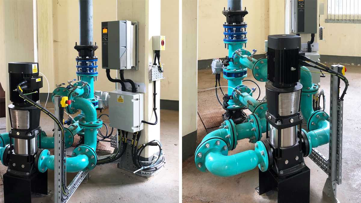
Danbury Water Tower booster pump – Courtesy of Essex & Suffolk Water
Construction work and operation
The installation of the new booster pumpsets was straightforward. The pumpsets were fixed onto a plinth, plumbed into the existing suction and delivery pipework, powered up, commissioned, chlorinated and put into supply.
The new configuration closes an actuated valve within the vertical leg of the tower outlet. This then diverts the water through the new booster pumps providing the required set pressures and flows.
Unlike the Danbury and Billericay Towers, the new booster pump installation at Hollingsworth Road could not be installed within the existing tower structure. Consequently, a new kiosk was constructed at the base of the tower with the underground pipework and concrete plinth fabricated by NWG. The pipework was left above the base to allow IWS to connect the new suction and delivery pipework to. The kiosk was ordered from Morgan Marine. Within the kiosk a new distribution board and small power and lighting was installed.
The pipework was designed and manufactured by IWS, to accelerate the programme, NWG carried out the vertical pipework installation including the valves and tees. The pump set pipework and variable speed drives were installed by IWS. The installations were commissioned by both parties.
It was possible to minimise disruption to customers during construction as each zone was supplied by the existing booster pumps whilst the installation was undertaken.
Billericay, Danbury & Hollingsworth Road Water Towers Low Pressure Project: Supply chain/key participants
- Client: Northumbrian Water Ltd (Essex & Suffolk Water)
- Principal contractor: Integrated Water Services (IWS)
- Principal designer: Integrated Water Services
- Instrumentation control & automation: Northumbrian Water Ltd
- Supplier of pumps: Grundfos
- Supplier of pipework: Integrated Water Services
- Supplier of variable speed drive: Danfoss drives supplied by Quantum Controls
- Kiosk: Morgan Marine

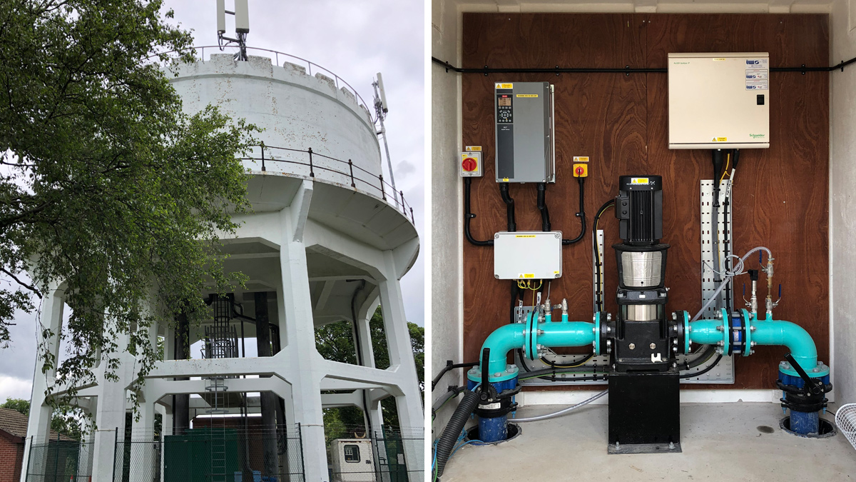
(left) Hollingsworth Road Water Tower and (right) the new booster pumps – Courtesy of Essex & Suffolk Water
Equipment
The pumps selected were Grundfos CR’s vertical multistage boosters which are controlled by new Danfoss aqua variable speed drives. To avoid lengthy lead times, the pumps at Danbury and Billericay were free issued from another scheme.
Danfoss was the preferred supplier for variable speed drives due to the time constraints and the presence of a 230V single phase supply at Danbury and Billericay, these were the only drives available to allow completion by the 31 March deadline. The flows and pressures required meant that a 3-phase pump set was required. A Danfoss drive was also selected for Hollingsworth Road for consistency and the lead time was more favourable.
The pump selection was validated at all sites by analysing flow and pressure data. The Danfoss drives work on a 230V single phase supply which it then converts to a 230V 3-phase supply, this meant that the motors for the free-issued pump sets needed to be replaced for 3-phase 230V to overcome the issue. Unlike Hollingsworth Road, Danbury & Billericay required the installation of a 230V Rotork actuated valve within the vertical tower outlet pipe to allow the water to bypass through the pump. To enable remote operation a signal to start or stop the pump and close and open the valve are sent from the control panel through the local site S2000 and onto the local pump set.
At Hollingsworth Road a new pressure transducer was also installed downstream of the pump to allow it to operate on an individual pressure control loop.
Conclusion
With a collaborative effort between NWG and IWS and support from supply chain partners the schemes were completed on time and within budget to meet the 31 March deadline. By relying on the collective experiences, skills and knowledge across the supply chain a solution was engineered on time, within budget and within quality parameters.


