Heaton Park Reservoir Liner Improvements (2022)
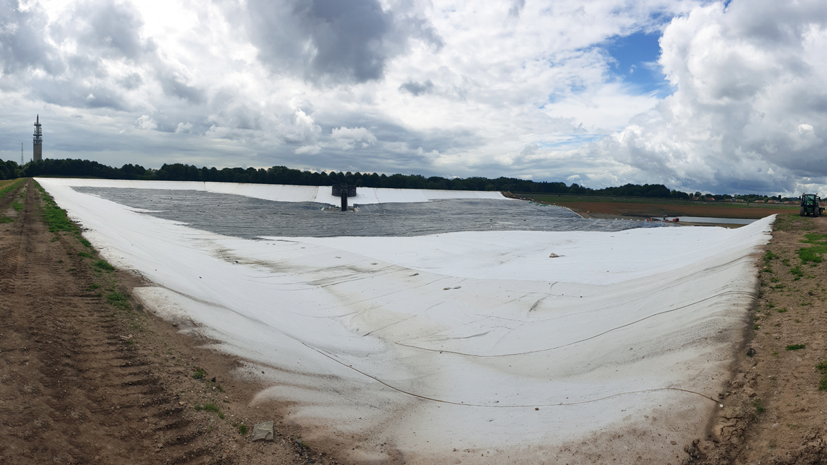
Completed liner system installation - Courtesy of Costain
Heaton Park Reservoir is located within Heaton Park, approximately 5 miles north of Manchester city centre. The reservoir is over 90 years old and has the capacity of 2,800,000m3 at top water level. The reservoir was previously used to store treated water for the Manchester Ring Main from Haweswater and Thirlmere aqueducts. However, since the closure of the water treatment works within Heaton Park, the reservoir is no longer used for public supply, but is required to receive flushing waters during maintenance outages on the two aqueducts.
Current facilities and reason for work
The reservoir is formed by a six-sided closed embankment in the shape of an irregular hexagon comprising earth fill with puddle clay cores. The floor of the reservoir is sealed by a clay blanket which is protected by stone revetment. There is an extensive drainage system under the clay blanket to prevent the groundwater within the underlying granular deposits from causing uplift and physical damage to this water retaining element.
The enhancement works were commissioned by United Utilities as part of ongoing maintenance and to support the planned strategically important Haweswater Aqueduct (HA) outage.
Using a robust design process to overcome challenges
The ultimate aim of the project was to install a lining system across approximately half of the reservoir, as well as reducing the top water level by 3.5m, specified by United Utilities to satisfy United Utilities’ outline design and meet new operating requirements. The design solution was achieved following an extensive collaborative design process between United Utilities Engineering, Costain and subcontractors.
Prior to starting on site, the reservoir needed to be emptied in order to allow the liner to be placed. This required forward planning and collaboration between the construction team, Manchester City Council and the Environment Agency.
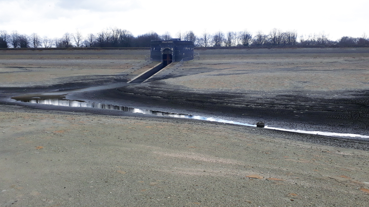
Reservoir basin once emptied – Courtesy of Costain
Discharge flow from the scour facility was limited to 10ML/day and the drawdown took place over four months to ensure integrity of the downstream catchment. This also required management of silt and pollution as well as regular monitoring to ensure compliance with the EA permit. In order to comply with the drawdown consent, straw bales were placed in the discharge bay. Daily turbidity filtering was also undertaken at agreed locations downstream of the discharge point.
The reservoir’s top water level (TWL) is controlled by a weir within an outlet tower building which was encased in reinforced concrete up to 5m above ground level. The initial design to reduce the top water was to replicate the existing detail at a lower level which would require careful demolition, working at height as well as noise, dust and the use of vibratory tools, along with the removal of waste. However, the construction team worked together with the designers to propose an alternative method of reducing the TWL.
Clearance works
As the reservoir had not been emptied for many years, there was a build-up of silt, vegetation growth and underlying debris. The liner specification highlighted that it must be placed on a clean and level surface, this meant the first operation was to clean the reservoir basin and remove the debris from site. This was done using a variety of methods such as strimming, scraping and cleaning with a suitable road sweeper capable of working on the steep embankments. Certain areas also required a concrete screed to remove sharp stone edges prior to placing the liner.
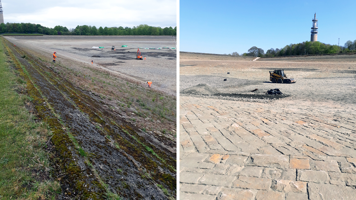
Clearance works – Courtesy of Costain
Liner placement
The lining system covers an area of 122,000m2 and comprised three separate layers supplied by Naue Geosynthetics Ltd (Bentofix® geotextile, Carbofol® geomembrane and Secutex® geosynthetic) placed on the embankments slopes for protection and to assist with access. The liner installation was undertaken by Sean Carr Lining Technology and was placed using excavators with a spreader bar before being anchored into the embankment clay core.
All joints were welded together and tested under the supervision of an independent engineer who managed the sampling and scheduling for on-site and laboratory testing.
Due to the restricted access on the embankment, phasing plans were essential to ensure productivity on site. Once the anchor trench had been excavated there was no access past this point which meant careful planning and regular meetings were undertaken to carefully devise the order in which to carry out the works.
More than 1,000 rolls were required to be delivered, off-loaded and transported around the reservoir basin; this again required careful logistical planning and appropriate methods to safely deliver the liner to its point of placement.
As part of the enabling works, a timber trackway road was laid to protect loading on the embankment from heavy plant and a tractor and trailer was used to transport the liner from the laydown area to the required point in the reservoir.
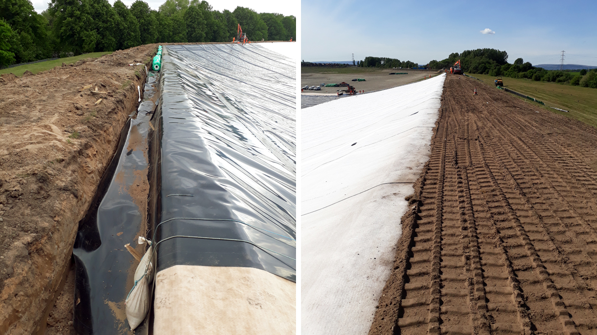
Anchoring of liner – Courtesy of Costain
Reduction of top water level
As opposed to replicating the existing weir 3.5m lower, the proposed solution was to core through the existing structure and construct a weir at the revised top water level, leaving the original pipe and concrete in place whilst still providing the same outfall requirements for the reservoir. The weir was made safe by providing a gated handrail system to improve access for future maintenance for the client. This required a collaborative approach with the client, contractor and designers to implement the revised design solution.
Heaton Park Reservoir Liner Improvements: Supply chain – key participants
- Client & outline design: United Utilities
- Project delivery & lead designer: Costain
- Designer: GHD
- Main contractor: Bethell Construction Ltd
- Liner installation: Sean Carr Lining Technology Ltd
- Liner manufacturer: Naue Geosynthetics Ltd
- Quality testing: Wardell Armstrong
Delivering benefits
The design solution led to a number of benefits including:
- Liner placement allowed the operation of the reservoir for flushing water from the HA outage as planned.
- Ensuring ongoing embankment safety under new operational parameters.
- The design solution for reducing the TWL led to a reduction in programme of two weeks as well as financial savings for the client.
- The shorter programme led to a reduction in carbon emissions and the design solution meant a saving in embodied carbon of the materials that are going to be left on the project (a reduction of 32 tonnes of reinforced concrete).
- The solution led to a reduction in noise, dust and vibratory tools which have high vibration levels and as the works were competed without entering the building, there was no requirement for working in confined spaced.
- As the new top water level is 3.5m below the previous level, all work was done from ground level with no working platforms, harnessing or ladders required making the job much safer and easier to complete.
- The design removed the need for working within a building that is more than 90 years old and contains sensitive mechanical and electrical equipment. The new arrangement also improves access for maintenance in the future.
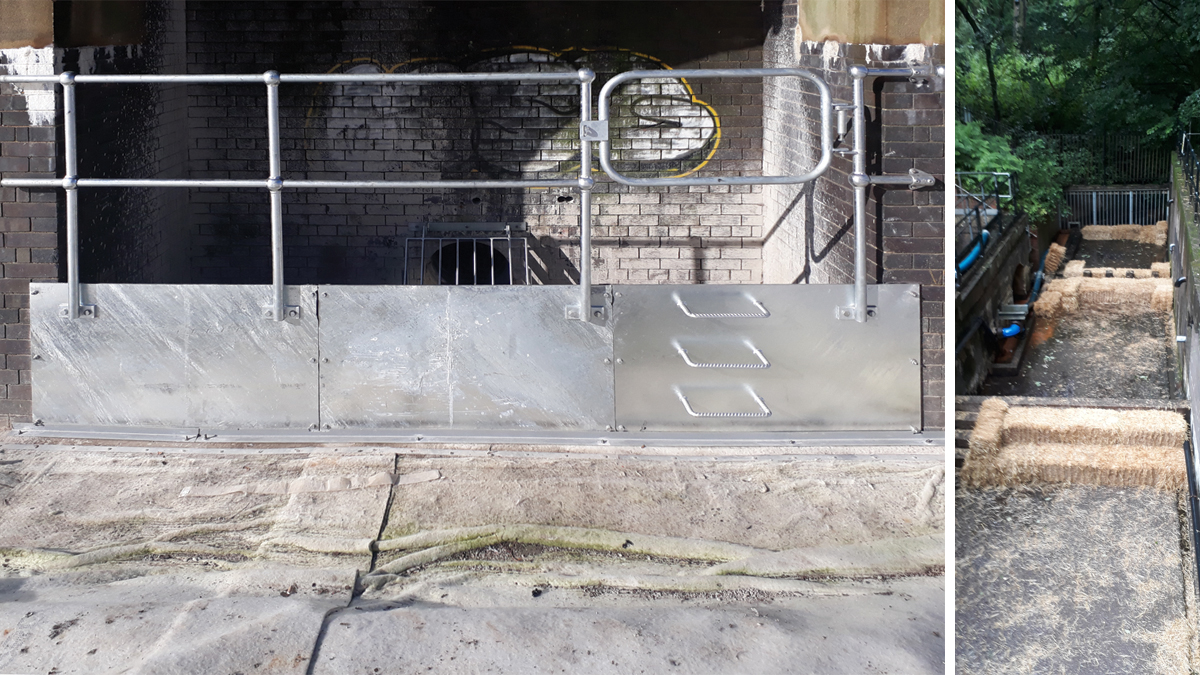
New overflow weir – Courtesy of Costain
The design process allowed adequate time to review designs and discuss with all parties, including the client and supply chain to understand the drivers behind the project’s requirements. By understanding the client’s needs and working closely with the subcontractors on site, the solution provided the client with the desired outcome, whilst removing/reducing risk during construction.
Conclusion
Overall, the robust smart design solution led to a reduction in programme length. The construction works were completed in just over six months and the site demobilised one month ahead of the planned Haweswater Aqueduct outage.
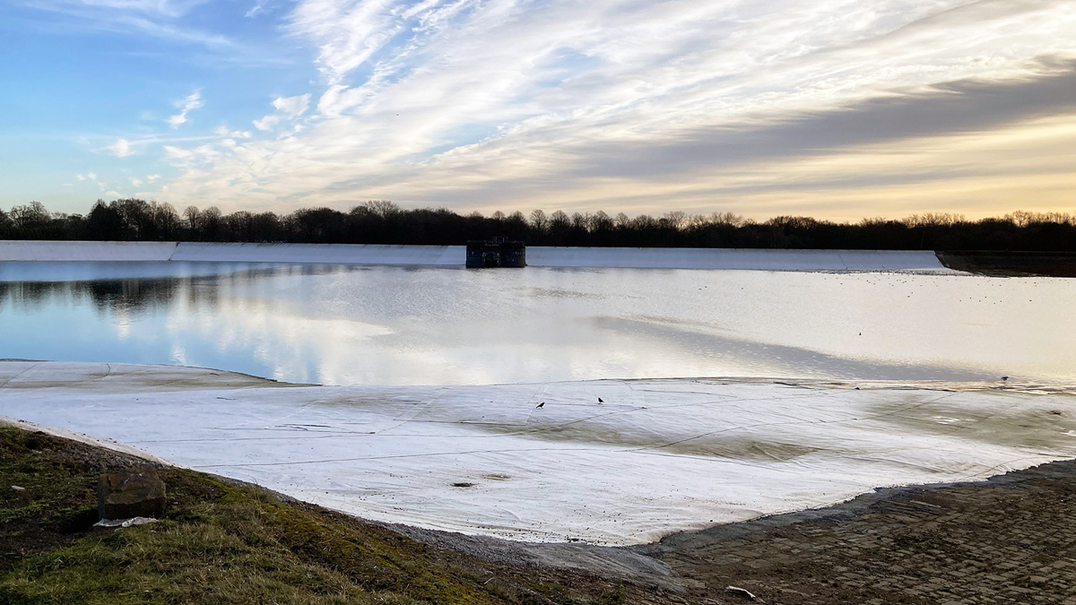
Heaton Park Reservoir post-construction - Courtesy of Costain


