
King George V Reservoir (2023)
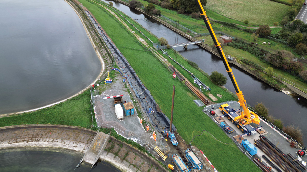
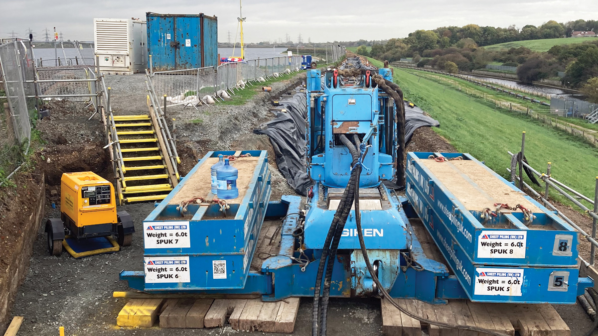
Overview of the piling works - Courtesy of Thames Water
King George V Reservoir (KGV) is an operational raw water storage reservoir located in the Lea Valley at Walthamstow and is a Site of Special Scientific Interest (SSSI) with restricted access. It is controlled by Thames Water’s Lea Valley/North London Abstraction Group based at Coppermills AWTW. Seepage through the clay core at the north-east of the reservoir was identified by a Willowstick survey in 2020. MWH Treatment was awarded a contract to address the seepage issue, with the works taking place 1.4km north of the main entrance from Lea Valley Road to the north of the tidal break on the east side of the reservoir.
History of the site
The reservoir was conceived as part of an overall plan for the Lea Valley and was laid before the Royal Commission of Water supply in 1893. At this time, the responsible authority was the East London Waterworks Company. Construction took place between 1908 and 1912, and the reservoir was opened by Their Majesties, King George V and Queen Mary in March 1913. At the official opening there was a ceremonial guard of honour review, and The King signed a Grant of Arms to the Metropolitan Water Board (owners and operators at the time).
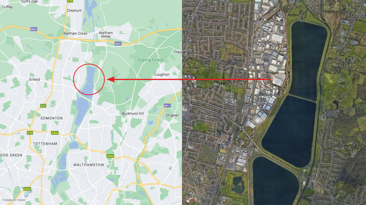
Google Maps – Location of King George V Reservoir
Description of the current facility
The reservoir was formed by the construction of a continuous embankment on the floodplain of the River Lea. An earth embankment divides the reservoir into two compartments that are connected by three large diameter culverts. The external grassed embankment supports a central puddle clay core.
The reservoir has a maximum capacity of 12,492 ML at its top water level (TWL) of 20.18m AOD. It is normally operated on a ‘put and take’ basis which at typical through‐flows of 60 to 100 MLD gives a theoretical retention period between 100‐150 days. The crest level is 22.50m AOD with a length of approximately 7km. The reservoir is operated in conjunction with other local reservoirs to provide a continuous supply of raw water to Coppermills AWTW and Hornsey WTW.
The embankment, wave wall and clay core were raised between 1938 and 1941 to restore the 1.5m design freeboard that had been lost due to gradual consolidation settlement. The reservoir was, however, kept 1.5m below original top water level, as a wartime precaution, until February 1945. At the higher TWL leakage occurred at several points, being attributed to dryness of the very high plasticity alluvial clays within the core; consequently, the current TWL was established.
A 4.5m deep grout screen was installed along an 800m length of the southwestern embankment in 1983 in an attempt to address the leakage.
Access to the reservoir is located at its southeast corner from the Lea Valley Road. This access is shared with a sailing club and activities club. Sheep graze the embankments as an environmentally sustainable way of managing grass growth.
Scope of works
The key scope of works for the project was the provision of a sheet-pile cut‐off wall. The wall was designed as 15m deep; based on the pile toe being driven into the London Clay a minimum of 0.5m, and 165m long; being installed between crest chainages 1,715m and 1,880m. A low vibration technique of pile driving was promoted to minimise potential for stability issues within the embankment during construction. The scope also included provision of access to the crest and provision of temporary access road, strengthening of existing site roads and protection to existing pipework and services.
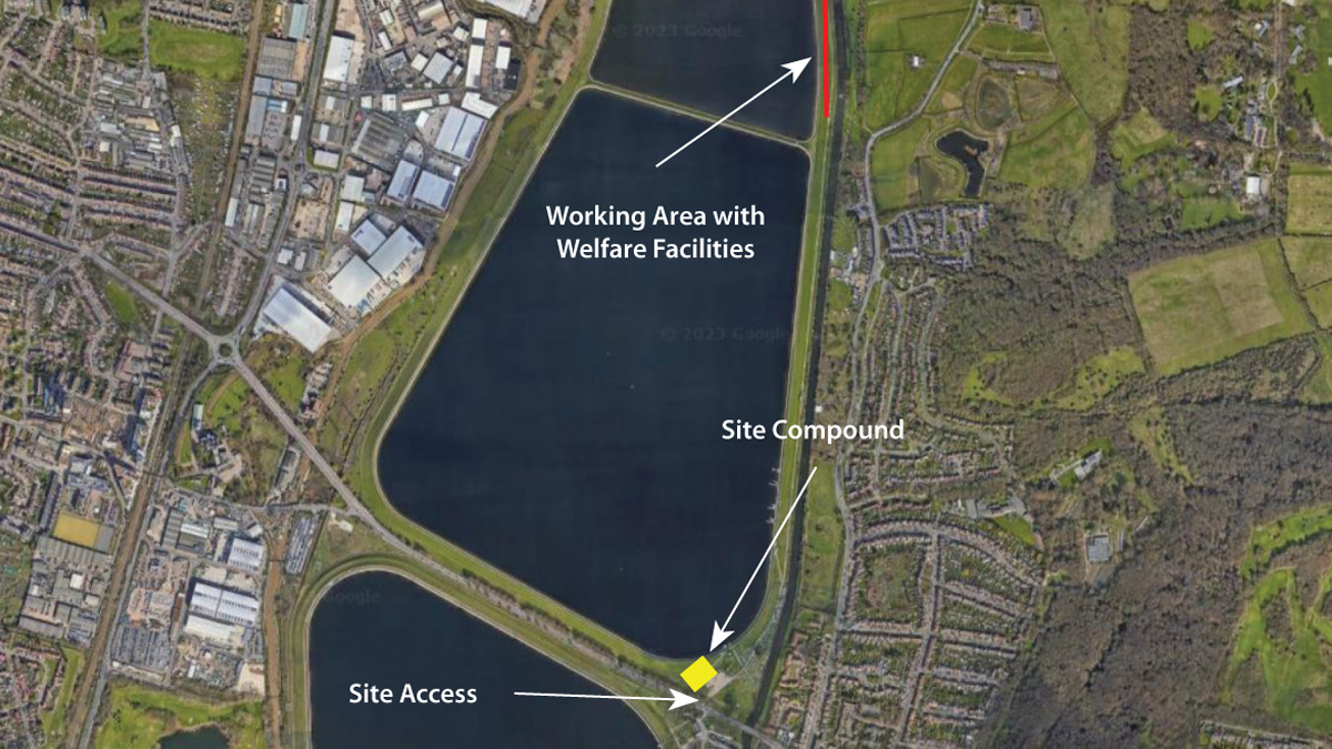
Google Maps – location of site compound and works area
Technical description
A survey was carried out late 2019 to early 2020 in the area around chainage 1,750m as this had been identified as an area of interest in a previous survey. Willowstick surveying is a non-intrusive geophysical method used to map and model the subsurface water flow paths. The procedure involves energising the study area with a signature electric current between paired electrodes. The surveying equipment consists of GPS system and an instrument known as a Willowstick which measures the magnetic field response of an electric current. As the electric current flows through the survey area the preferential flow paths are identified, mapped, and modelled. The information gathered can be used in making informed, guided, and cost-effective decisions concerning how to further, monitor, intercept and mitigate seepage.
The main findings from the survey were:
- A weakness zone of preferential flow identified between chainage 1,723m and chainage 1875m.
- The flow path shows the characteristics of uniform sheet flow and did not indicate a concentrated leakage path, rather a 150m zone where water was passing evenly through the core.
- The preferential flow was identified at elevation 12m AOD through the foundation underneath the embankment.
- The preferential flow path strongly correlated to the location of the original stream channel. Its characteristics indicated that seepage was concentrating in flood plain sediments deposited by the original river channel meandering through and beneath the survey area before the dam was built.
The survey report recommended remediation works in this area within a short timeframe to reduce any movement or damage to the reservoir embankment.
King George V Reservoir: Supply chain – key participants
- Principal contractor/designer: MWH Treatment
- Designer: Atkins
- Temporary works design: Noble Works Ltd
- UXO survey: 6 Alpha Associates
- Ground investigation, soil testing: Structural Soils
- GPR surveys: Technics Group
- Environmental surveys: Middlemarch Environmental
- Willowstick survey: Willowstick UK
- Noise & vibration monitors: RSK Acoustics
- Silent piling contractor: Sheet Piling (UK) Ltd
- Piling verticality survey: CMCS Ltd
- Civil works, labour/plant: Derryard Construction limited
- Electrical (site setup, gate works): SRS Electrical
- Ground maintenance: UK Landscapes
- Scaffolding/access: Clocktower Scaffolding
- General plant hire: GAP Group Ltd
- Welfare supply: Wernick Group
- Supply of Trakway Matting: Sunbelt Rentals
- Ductile iron pipework: Electrosteel Castings (UK) Ltd
- Valves: Glenfield Invicta
- CCTV, timelapse cameras: Wireless CCTV Ltd
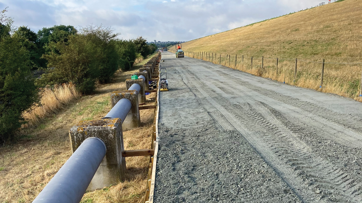
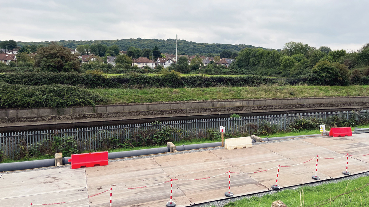
Finished temporary road before track matting – Courtesy of MWH Treatment
Toe road and crane pad
Atkins were instructed to advise on embankment loading constraints, construction methodology and the sheet pile solution. They developed the initially suggested remedial works to achieve a detailed solution which was then agreed with Thames Water.
The existing track at the toe of the embankment was the only access route to the works area. The track had a loading capacity of 12t and the crest road a 5t weight limit; both limiting machinery and plant selection. A previous project adopted an 8t excavator and 6t tracked dumpers and Atkins used this information within their assessment to complete a slope stability analysis of the embankment. This confirmed that the use of an 8t excavator was acceptable for the works on the crest road.
An existing 30” pre-stressed concrete (PSC) pipe main under the road at the toe of the embankment further constrained the size of vehicles to be used during construction and required enabling works. A disused section of pipe was recovered and tested to confirm dimensions and the material characteristics to be used in the loading analysis. Atkins confirmed that the pipe had sufficient capacity to support a maximum axle load of 12t.
A temporary road was installed to minimise rutting and dynamic loading on the existing track. Trackway matting was installed from the sailing club ramp to the crane pad to disperse vehicular loading and mitigate impact on the pipe and vehicle speed was restricted to 5mph for all vehicle movements. An emergency plan was put in place to ensure the Thames Water Operations team were made aware of any incident and to cover the eventuality of a pipe burst.
The temporary road was designed by Noble Works Ltd and installed by Derryard Construction Ltd over a period of 8 weeks. Over 1km of track matting was hired from Sunbelt Rentals and installed over a period of 2 weeks.
Along with the temporary road, a crane pad was installed to facilitate the 200t crane used to lift the piling equipment and sheet piles from the toe to the crest of the embankment. The crane pad was designed by Noble Works Ltd and constructed in MOT Type 1 granular fill by Derryard Construction Ltd. A section of the adjacent aquifer recharge pipeline was dismantled to facilitate construction of the crane pad which also included a concrete protection slab above existing underground HV and telecommunications cables.
Finished installation of the track matting – Courtesy of MWH Treatment
Piling decision
Following previous successful remediation works carried out at Sir William Girling, Staines South, and Island Barn Reservoirs, MWH Treatment selected Giken silent piling. This is a vibration free press-in method that allowed the pile installation to be virtually silent.
This technique enables the piling plant to ‘walk’ over the tops of the driven piles. The initial press-in to install the dummy piles was carried out utilising a reaction platform. The Giken rig then used the previously installed piles to generate reaction to enable on-going pile installation.
The sheet piling works (undertaken by Sheet Piling (UK) Ltd) commenced at chainage 1,880m which is the junction of the perimeter and the reservoir dividing embankments. A wider toe area had been identified as a turning and laydown area for the storage of equipment. It was also used for the reaction platform for the installation of the dummy piles.
The first 100 piles were fed to the rig by the crane at the base of the embankment. Once the radius of this crane was exceeded, the ‘non-staging’ method was adopted utilising a clamp crane and pile runner to move the piles along the crest and to feed the piles to the Giken rig.
A 15m long PU32 section pile was adopted being dependant on the chosen method of installation, length of pile and expected ground conditions. The pile clutches were lined with sealant to ensure low permeability through the wall joints.
Press-in driving of the piles with the Giken rig was assessed as feasible with hard/difficult driving being a low risk when reaching the London Clay layer. Subject to the approval of the reservoir Qualified Civil Engineer (QCE) water jetting was an option to achieve required toe penetration.
Reaction stand setup excavation – Courtesy of MWH Treatment
Crest road works
The Giken piling method minimised the access width requirement to work on the crest, however some excavation was still required. Using an 8T excavator the crest road was excavated to expose the clay core to allow the alignment of the sheet pile wall with the centre of the core. The base width of the trench was specified at 2m to allow the Giken rig to operate. The top of the core was covered with plastic sheeting to prevent desiccation and protect the clay core from being damaged. Following the completion of the sheet piling works, the trench and crest was reinstated.
Site installation of the piles
Sheet Piling (UK) Ltd commenced work on site at the end of October 2022, with a planned 10-12 week site duration. The 200T attendant crane was stripped of all non-essential weight in order to maintain the 12T per axle load weight restriction. Once in position on the crane pad a smaller 45T service crane off loaded the initial crane ballast and commenced rigging; once part rigged the remaining ballast was self-rigged.
The reaction stand was lifted into position by the 200T crane to the 6m x 6m hardstanding area finished 600mm below the top pile design level. The Giken rig was then positioned onto the reaction stand followed by counterweights. The first pile was then driven utilising the weight of the rig and counterweight as reaction.
After the first pile were installed, it became a reaction pile for subsequent piles to be installed. When the rig fully sat on the dummy piles, the reaction stand and counterweights were removed. Once a pile was sufficiently driven and stable the rig releases its clamps from the reaction piles and travels forwards. This ‘self-moving’ system eliminates the need for support by a crane during the piling operation.
Following installation of the first 100 piles a clamp crane was utilised as the piling works had exceeded the working radius of the 200T crane. After the clamp crane had travelled along the piles as far as possible inside the 200T crane working radius a track, formed of a temporary pile welded along the completed wall, allowed a handling train to deliver the piles to the clamp crane.
Pile verticality was critical as the piles must not exit the puddle clay before penetrating the underlying London clay. During piling verticality was monitored via spirit level. Once completed Sheet Piling (UK) Ltd employed CMCS Ltd to undertake a verticality survey. This included the first five 5 piles and then 10% thereafter, resulting in a total of 32 tests. CMCS Ltd utilised the lancing tubes on the piles that were welded prior to installation. The data reported the tilt of the pile and to what extent, whether leaning towards or away from the reservoir.
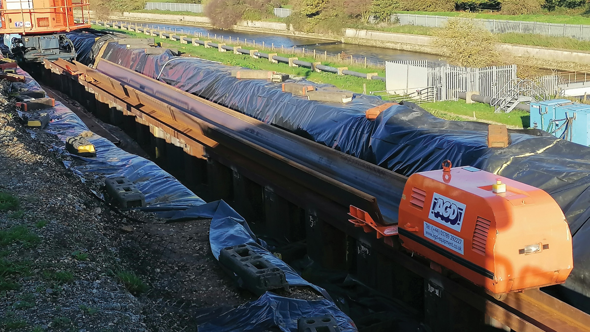
Train moving a pile to the clamp crane – Courtesy of MWH Treatment
Success of piling solution
After the first week of initial set up and pressing of the 3 dummy piles, Sheet Piling (UK) Ltd installed 275 piles over the next 6 weeks. The site team completed the work in advance of programme despite difficult weather conditions. The crest of the embankment was very exposed; strong cross winds resulted in several days when piling was prevented, but the team were able to boost productivity to recover lost time. The Sheet Piling (UK) Ltd team de-mobilised mid-December; this was during the weekend of a severe snowstorm with over 6 inches falling over the Sunday night.
The MWH Treatment team and subcontractors mobilised additional resources to clear the site of snow, including the 1km toe road, enabling several lorries and the 200T crane to safely leave site. Site demobilisation took place earlier than planned realising 3-weeks’ efficiency on the track matting hire period.
After the Christmas shut down, the trench on the crest road was reinstated and an embankment survey was carried out by Derryard Construction to confirm the final ground levels were within tolerance.
A post-installation Willowstick survey was conducted which reported that the previous flow path had been cut-of. The sheet pile wall appears to be working as designed by cutting-off the preferential flow of electric current through and beneath the northern half of the sheet pile wall; interpreted as cutting off the seepage flow. The post completion survey confirmed that the remediation works had been successful.
Biodiversity
The King George V Reservoir is a major wintering ground for wildfowl and wetland birds, including nationally important species. A total of 85 wetland species have been recorded and the reservoir also forms a moult refuge for a large population of wildfowl during the late summer months. Over the course of the project environmental consultants Middlemarch visited site monthly to monitor bird activity and to ensure site works were not affecting wildlife.
The site compound took up the space of the sailing club/water sports club car park so MWH Treatment constructed a temporary car park providing sailing club patrons with continued safe parking. On project completion it was agreed with Thames Water that the car park should become a permanent overflow car park. A wildflower meadow is being planted to compensate for the biodiversity loss of the car park.
Conclusion
MWH Treatment have delivered a very successful project overcoming access, logistic, weather and environmental challenges. The sheet piling cut-off wall achieved the desired project outcome: mitigation of water seepage. The project was delivered early with an excellent safety and environmental performance. Thames Water additionally gained an upgraded toe road and improved protection for critical services. The project also fostered and maintained excellent relationships with neighbours at the sailing and activity clubs.