
Lluest Wen Reservoir (2023)
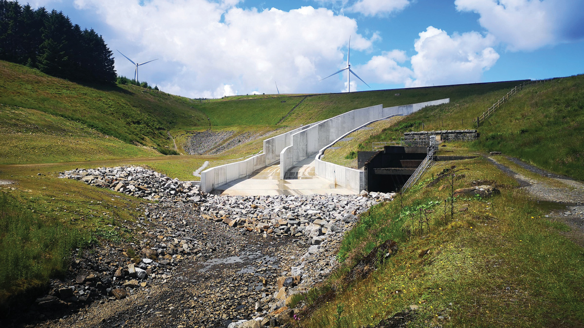
Finished spillway from watercourse - Courtesy of MMB
Located near Maerdy in South Wales, Lluest Wen Reservoir is a Category A Large Raised Reservoir as defined by the Reservoirs Act 1975. The reservoir is impounded by a 200m long, 25m high earth embankment dam across the Rhondda Fach River and currently impounds 1.07Mm3 of water. Construction of the reservoir was originally completed in 1898. Lluest Wen Reservoir is owned and operated by Welsh Water and has historically been used with a smaller, downstream reservoir, Castell Nos for water supply.
Investigation and scope
Following an inspection of the reservoir in February 2018 under Section 10 (3) of the Reservoirs Act 1975, the Inspecting Engineer made a series of recommendations for measures to be taken in the interests of safety (MITIOS).
These recommendations included that flows through the spillway chute be modelled under the 10,000 year and probable maximum flood (PMF) conditions, that the performance of the chute arrangement be evaluated in safely conveying the associated flows to aid scoping remediation works and to action any works as necessary to preserve dam safety. The improvement works were statutory and enforceable by the regulating authority Natural Resources Wales.
Mott MacDonald Bentley (MMB) was commissioned to undertake the design and construction of the works under Welsh Water’s Capital Delivery Alliance framework.
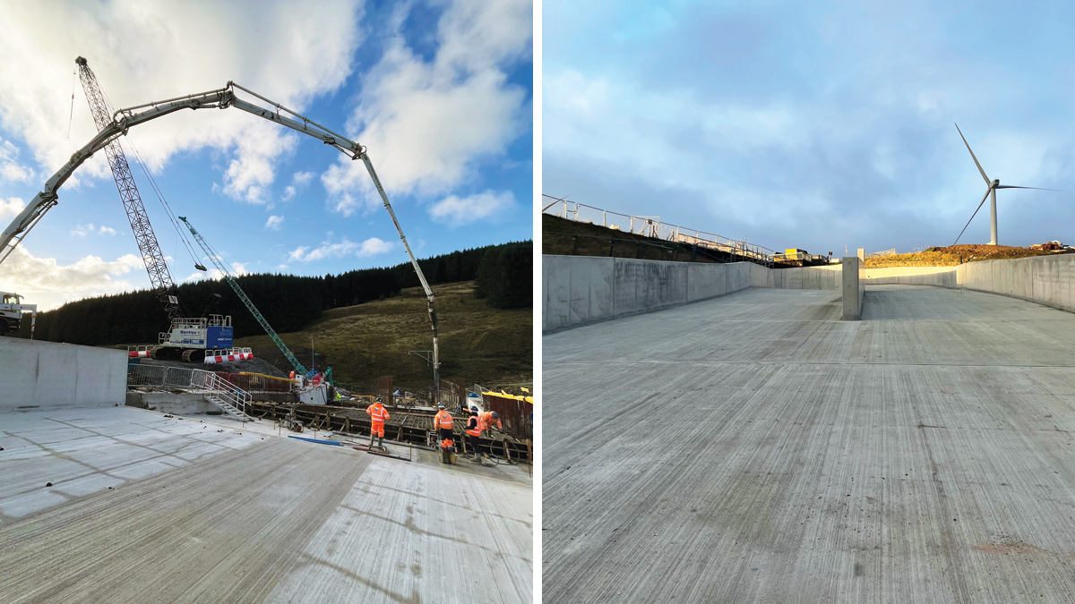
(left) Base concrete pour and (right) the upper spillway – Courtesy of MMB
Lluest Wen Reservoir Spillway Remedial Works: Supply chain – key participants
- Principal designer & principal contractor: MMB
- Flow modelling: Mott MacDonald
- Ground investigation: Strata Geotechnics
- Geophysical surveys: Terradat
- FRC works: Concrete Structures & Floors Ltd
- Metalwork: Industrial Pipework Services Ltd
- Diving works: Edwards Diving Services Ltd
- Manholes: Marshalls CPM
- Drainage pipework: Polypipe Civils and Green Urbanisation
- Concrete cutting & drilling: Holemasters
- Concrete supply: Hanson UK
- Scaffolding: Mii Engineering
- Site buildings: Wernick Hire
Flow modelling and spillway design
Prior to the scheme commencing, the existing flood study was reviewed and updated to reflect current industry guidance. A computational fluid dynamic (CFD) model was developed to simulate conveyance of the PMF and 10,000 year conditions. The PMF scenario anticipated flows approaching 100m3/s, with peak velocities approaching 20m/s discharging through the spillway.
Outputs from the model indicated that the existing spillway was unable to contain flows arising during each flood scenario therefore representing a risk to dam safety through erosion of the earth fill embankment.
An Options Report was prepared to identify possible solutions to remedy the shortfall in spillway capacity. The report considered the following options for remediation:
- Construct a new spillway off-line along a straight alignment.
- Rebuilding the spillway along the existing alignment.
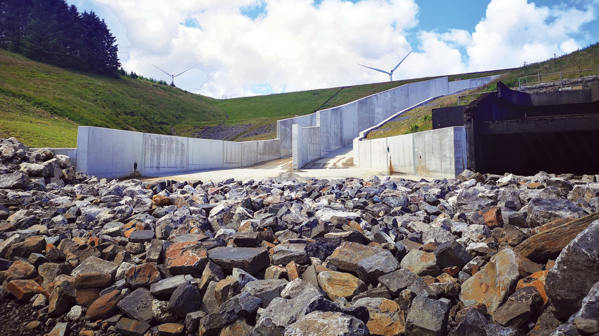
Armourstone and lower spillway – Courtesy of MMB
Preferred option
The preferred option was to re-build the spillway along its existing alignment. This would involve re-lining the upper section of the spillway which had previously been re-built in concrete during the 1960s. Lining would take the form of a 500mm thick reinforced concrete base connected to the underlying structure via a system of dowels. A similar approach would be taken for the downstream section of the spillway following demolition and removal of the historic masonry structure. Through this section, the new spillway base was doweled to a layer of mass concrete provided for global stability. New spillway walls were constructed on the hydraulic left and right hand sides capable of containing the PMF flows having utilised the CFD model to rationalise the wall heights as far as practicable. Additionally, a central training wall was provided through upper and lower sections of the spillway to evenly distribute flows across the width of the spillway and reduce water superelevation at the two changes in direction.
The CFD model was also used to extract hydrodynamic pressures which allowed optimisation of the reinforcement within the walls and bases. Global stability checks for bearing, sliding, overturning and seismic were also undertaken to verify the suitability of the design. The new spillway construction would be approximately 200m in length and 15m at its widest point. Additionally, new drainage networks would be provided to the back of walls to control groundwater levels and underneath the spillway base to protect the formation and prevent undermining of the spillway base. At the downstream end, armour stone was provided for scour protection.
Temporary works
A 90-tonne crawler crane was used to provide full coverage of the spillway footprint. In order to access the embankment side of the spillway, it was necessary to construct a number of culverts, embankment and roadway at the downstream end of the spillway to cross the receiving watercourse. The upstream face of the bridge was concreted to prevent erosion and migration of fill into the downstream watercourse.
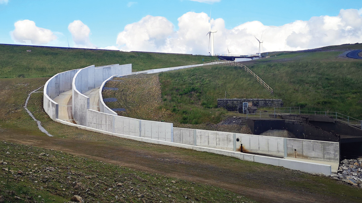
Finished spillway – Courtesy of MMB
Design considerations
The gradient at the lower section of spillway approaches a fall of 1 in 2 which presented significant challenges both in terms of pouring and finishing the concrete bases as well as the flow velocities generated within the spillway. Base pours lengths were reduced to 3m and the bays were installed in a hit and miss sequence through this section in order to prevent slumping of the concrete prior to curing. High flow velocities necessitated that the joints be protected with steel plates to prevent scouring of the joint sealant and significant hydrodynamic pressures developing on the underside of the downstream base. Particular care had to be taken to ensure the absence of abrupt deviations across the joints which could invoke cavitation and ultimately lead to concrete degradation.
The water level in the reservoir is known for rising quickly during periods of extended or heavy rainfall due to its location. A temporary drawdown of 3m below top water level was initially agreed with Welsh Water and a robust management plan was implemented to prevent the spillway from operating during the construction phase.
Completion
The scheme was mobilised to site in October 2020 beginning with improvements to the access track to the reservoir. Concrete works were scheduled to commence in late March 2021. Following a dry summer, concrete works were completed by January 2022 with landscaping and other finishing works completed by June 2022 whereupon the Qualified Civil Engineer issued the 10(6) certificate ahead of the required October 2022 statutory deadline.
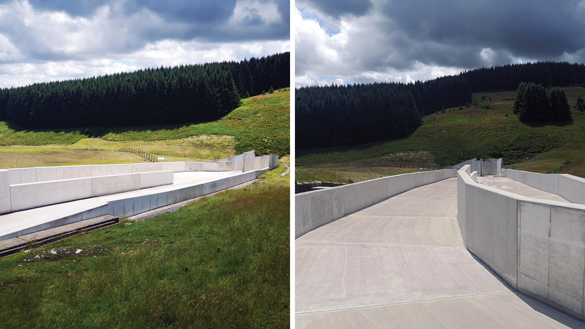
The finished spillway - Courtesy of MMB