
Lower Barden Reservoir (2023)
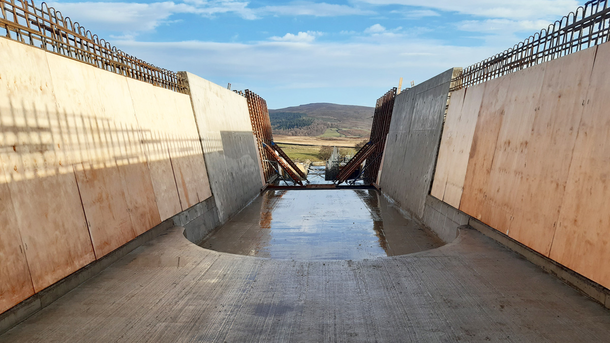
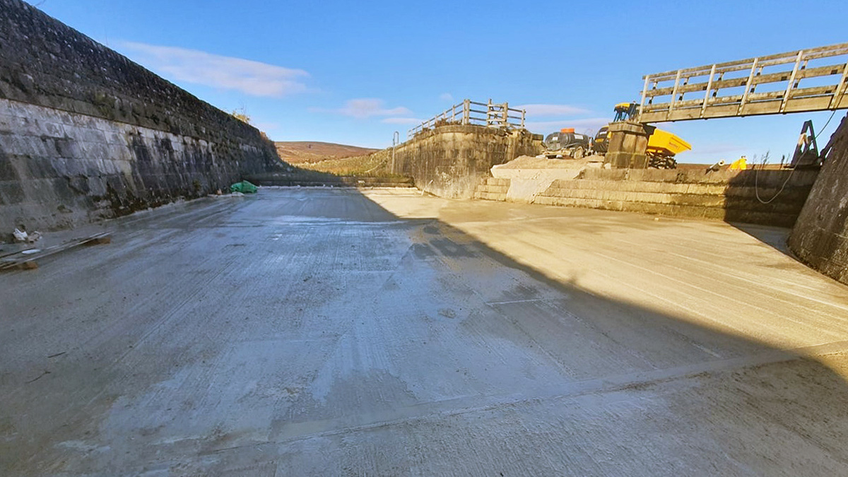
Lower Barden Reservoir reinforced concrete spillway channel - Courtesy of MMB
Lower Barden Reservoir is the lower of two reservoirs located near Bolton Abbey within the Yorkshire Dales National Park. The reservoir is an impounding reservoir with a crest length of approximately 640m and a maximum height of 28m with a capacity of 2.23 Mm3. The overflow is located on the right-hand side of the embankment and consists of a curved masonry weir, a tumble bay, then twin masonry culverts before discharging into a straight stepped spillway. The spillway chute consists of a series of curved steps with vertical upstands forming pools. Lower Barden Reservoir is owned and operated by Yorkshire Water Services (YWS).
Investigation works
Due to its capacity, the reservoir is subject to The Reservoirs Act 1975. Within Section 10 of the Act, safety inspections are required to be carried out by an Inspecting Engineer at least every 10 years. Under the most recent report, there were several matters in the interest of safety (MITIOS) including:
- Improve the drawdown capacity so that it may be lowered by 925mm per day.
- Install under-drainage to intercept leakage and carry it to a remote measuring point from the spillway culverts.
- Improve the hydraulic performance of the stepped chute to eliminate out of channel flow to a distance of 150m downstream.
- Modify the auxiliary spillway channel (above the culverts) to prevent floodwater escaping out through gaps in the crest access track.
Following investigations into the drawdown by Stantec UK and the spillway condition and capacity (investigated by MMB in the previous AMP and continued through to definition by Stantec), the following recommendations were given:
- Increase the spillway wall height and remove the pooled element of the spillway structure to contain the probable maximum flood flows and reduce hydraulic jump issues due to the pooled nature.
- Replace the top layer of masonry in the tumble bay with concrete and introduce under-drainage.
- Install a new 800mm diameter siphon pipe to be able to lower the reservoir a minimum of 925mm per day down to 5.0m from top water level.
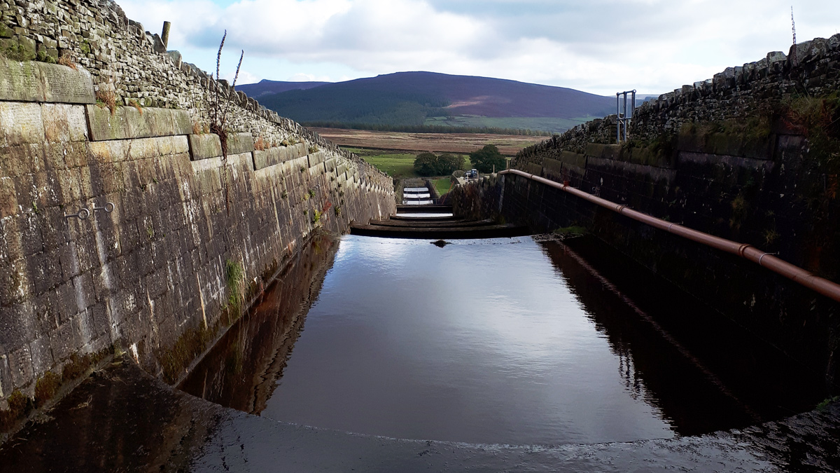
The original spillway channel – Courtesy of MMB
Planning application
The scheme is situated within a national park and due to the size and scale of the modifications, it was subject to planning application. The development must be aligned with the National Planning Policy Framework (NPPF), including conserving and enhancing the historic and natural environment, achieving sustainable development and achieving sustainable development.
To aid in ensuring that these items within the planning frameworks were addressed, specialist reports were prepared, utilising specialists within the Mott MacDonald group to develop them, including Heritage Statements to analyse the historic significance of the existing structure and the impact the new development may have, landscaping and visual assessments and photomontages to show visual impact of the new development from public view points and preliminary ecological appraisal (PEA) to assess the ecological impacts of the development.
These reports along with a Planning, Design and Access statement and relevant design drawings were provided to Yorkshire Dales National Park and a constructive dialogue between the designer, the planning officer and Natural England for issues with respect to site access began, with planning permission received in April 2022.
Lower Barden Reservoir Safety Improvement Works: Supply chain – key participants
- Client: Yorkshire Water
- Planning application: Mott MacDonald
- Outline design (siphon & spillway): Stantec UK
- Outline design (spillway) and detailed design & principal contractor: Mott MacDonald Bentley
- Concrete works: Offafix Formwork Ltd
- Masonry cladding: Colin Richards
- Various steelworks: George Green (Keighley) Ltd
- Pipework supplier: Powerrun Pipe-Mech Ltd
- Valve Supplier: Glenfield Invicta
- Hydraulic actuation: Varley Hydraulics Ltd
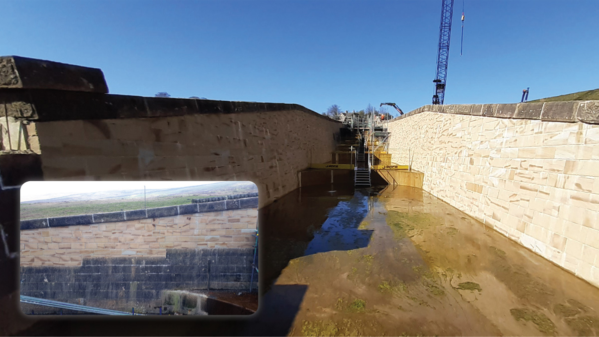
Completed masonry cladding on spillway, and (inset) wall raising showing new and existing masonry – Courtesy of MMB
Spillway
The spillway channel was designed as a combination of wall raising and new reinforced concrete construction. Wall raising was used as much as practicable to utilise the existing structure. Some minor amendments were conducted in the detailed design stages for the spillway structure, such as maintaining the sloped nature of the walls to the top, which maintained the heritage of the structure, along with maintaining the curved nature of the steps within the spillway and cladding the internal faces with masonry. The masonry selected came from a nearby quarry so that the stone was in keeping to the surrounding area, however it was requested that the colour did not match in order to show the history of the development from a planning and heritage perspective.
The original design included steel reinforced concrete throughout the construction. This was challenged and where applicable, for bases which were not carrying large moments and infill sections of clad walls, a change to fibre reinforced concrete was used. This mix was developed with aid from the fibre supplier and fibre designer to make sure that the fibre dosing could take the maximum loadings anticipated.
Using fibre reinforced concrete instead of steel reinforced concrete led to a reduction in construction programme due to no steel fixing and lead to an approximate reduction in embedded carbon of 9000kgCO2.
Siphon
The initial design of the siphon was carried out by Stantec UK and passed across to MMB for detailed design. The siphon was designed to be self-priming at top water level, requiring manual priming at levels lower than its pipe crest level. The siphon is capable of drawing down the reservoir to approximately 5.0m from top water level, achieving the requirements stipulated in the S10 report.
During the initial design stages, MMB aided in the development with Stantec UK due to the interaction with the spillway. A solution was reached where the new siphon would discharge through the floor of the newly developed spillway, along with some minor amendments to the hydraulic design of the siphon. A chamber was proposed to house the downstream valve adjacent to the stilling basin.
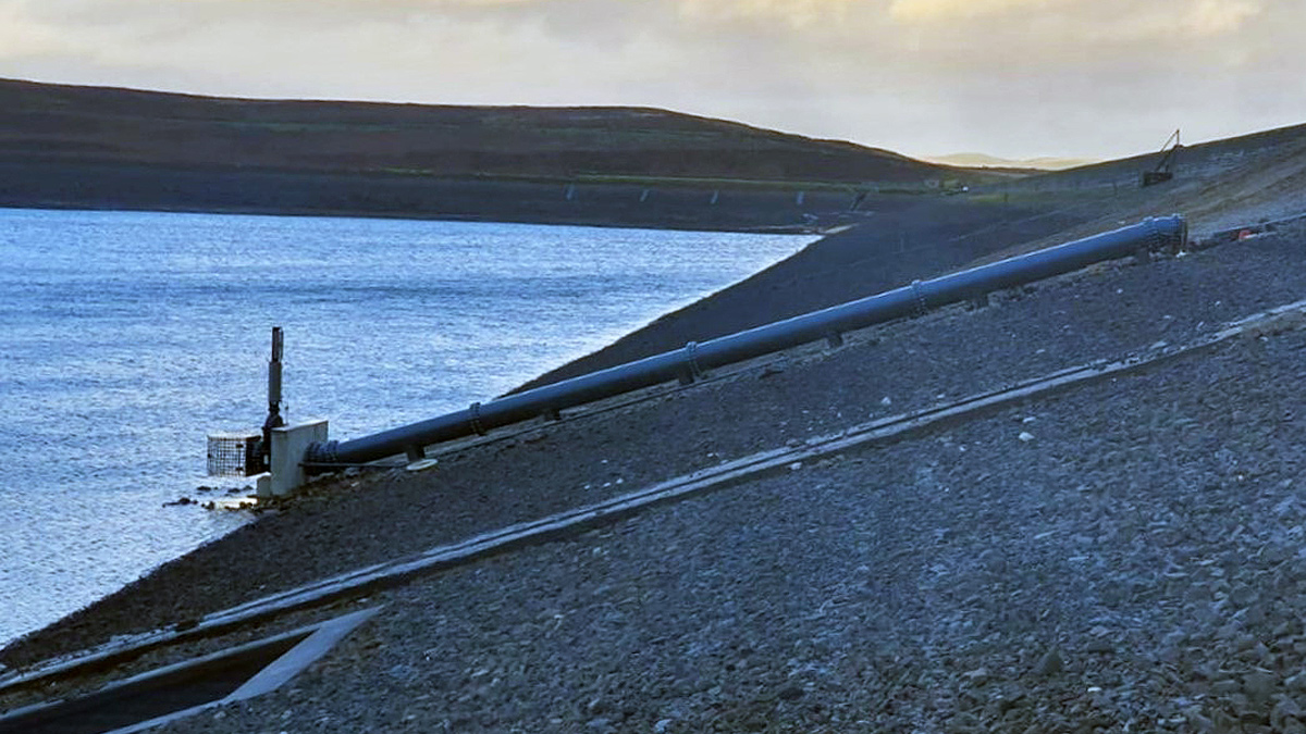
Upstream leg of siphon – Courtesy of MMB
Due to the levels of communication between Stantec and MMB, this additional chamber was designed out and the chamber was moved into the stilling basin, prior to it being backfilled to contain the spillway flows. This reduced additional excavation works and aided in the construction programme, promoting some carbon efficiencies. Good communication between both parties ensured that both projects were capable of being delivered within programme and reduced abortive works.
Construction phase
Enabling works began in May 2022. Due to the restricted access, crane pads could only be placed on one side of the spillway and the programme of works needed to be carefully created to ensure that the two schemes worked in tandem, without blocking off access to each other during the spillway and siphon construction.
Offafix Formwork Ltd came on board to deliver the reinforced concrete structure and collaborated with the design team to ensure that the reinforced structure was buildable and if they had any comments to increase the effectiveness of the structure in terms of buildability and increase speed of construction this was welcomed and included in the design.
Fibre reinforced concrete tumble bay slab – Courtesy of MMB
The site team and stone masons chosen for the scheme comprised of the majority of those who had worked on the previously delivered Swinsty Spillway structure and had an in-depth working knowledge of constructing these structures. Their knowledge and experience greatly aided with the construction of the scheme and achieving the challenging programme.
The siphon works required a significant draw down of the reservoir level to be able to work on the inlet structure safely. As this was quite a long duration for the works, it would impact the programme significantly and equally impact the spillway structure. It was decided to work from both ends of the pipe where practicable and to use a make-up piece at a bend on the downstream side of the embankment. This would aid in any minor tolerance issues in the pipework and ensure that the pipe closed correctly.
To aid the construction of the pipework, the ICON system was used for setting out. This involved directly using the 3D modelling from the design of the pipe into a handheld tablet device and enabled accurate setting out, without the need to update drawings or continually check that the drawings were the most relevant. This also aided in delivering the as built positions of the pipework for the updates to the completion drawings.
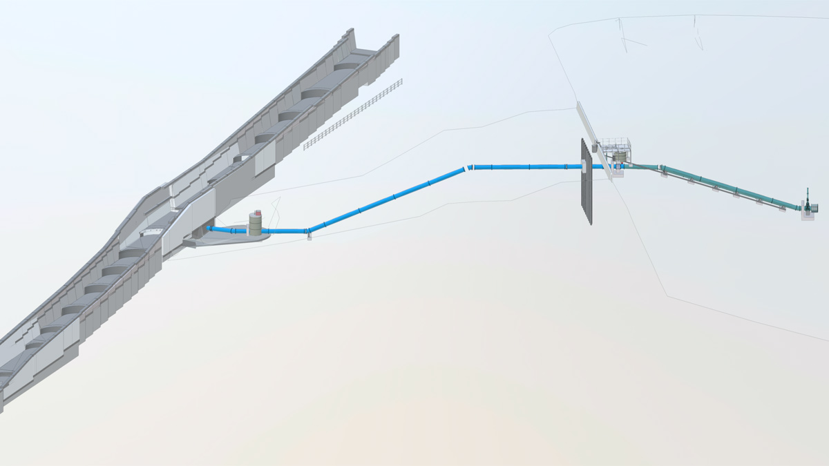
3D model showing the interaction between the spillway and siphon schemes – Courtesy of MMB
Conclusion
At the time of writing (April 2023), the scheme is in the final stages of construction with short sections of coping stone installation remaining and commissioning of the siphon when water levels in the reservoir are high enough for this to take place. The scheme had a very challenging programme to reach and was able to beat the programme set at Clause 31.
The main successes of the scheme were the reduction in embedded carbon using fibre reinforced concrete where applicable, the high level of communication across the scheme between third parties, planners, consultants, client, the design team and the site team and the quality of the finishes of the structure.