

Middle Aston WBS (2025)
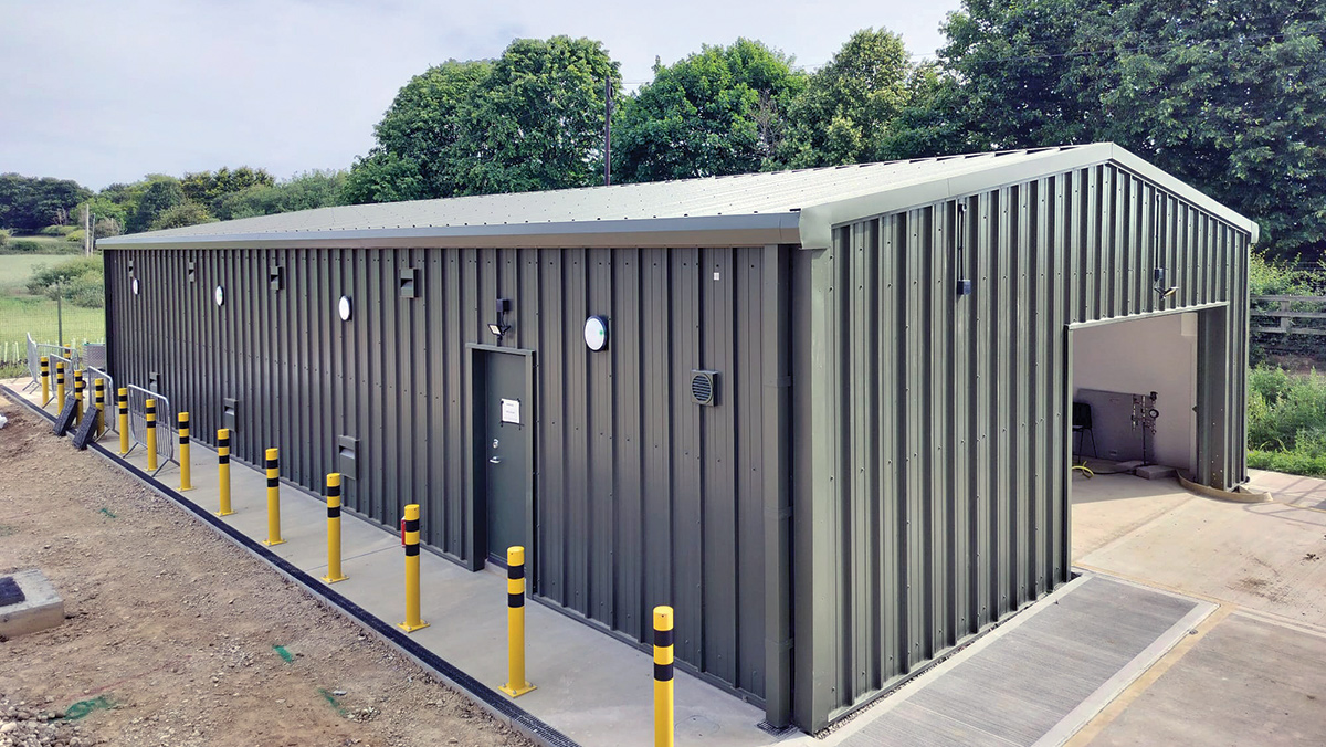
Middle Aston WBS - Courtesy of Ward & Burke
Angelinos Water Booster Station (WBS) supplies water to the Bretch and Duns Tew Flow Monitoring Zones (FMZs). As part of Thames Water’s AMP6 progamme of works, the Angelinos Trunk Main Project involved the installation of a new ductile iron main parallel to an existing concrete main to enhance the resilience of the network. However, operation of these mains led to insufficient head available to fill Duns Tew Reservoir, which is a key requirement of the system operation. As such, following the installation of the second main, the system continued to utilise single main operation with a sweetening flow into the second main. A new WBS was therefore required to enable the network to perform as required during dual-main operation; allowing the resilience benefits of dual-main operation to be yielded.
Background
The flow from Angelinos WBS feeds Duns Tew Reservoir via the Middle Aston Valve, and feeds Bretch Reservoir from the Banbury Ring Main, with assistance from Milton WBS. The AMP6 pipeline extends from Angelinos WBS to the Banbury Ring Main, providing dual pipelines from Angelinos to Middle Aston Valve and from Middle Aston Valve to the Banbury Ring Main. This provides resilience to the system by providing redundancy against burst failures both upstream and downstream of the Middle Aston Valve.
There are several operating modes of the system whereby there is insufficient head available to fill Duns Tew Reservoir, either due to outages of network assets or during dual operation of the pipelines from Angelinos due to the reduction in hydraulic gradient.
It was identified that a new water booster station constructed at the location of the Middle Aston Valve would enable a continued supply to the Duns Tew Flow Monitoring Zone for multiple different operation/outage scenarios, providing resilience to the network. Ward & Burke Construction was appointed by Thames Water to design and build the new pumping station.
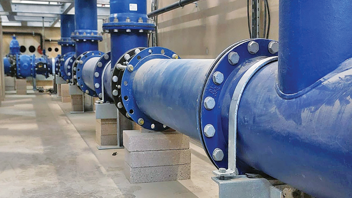
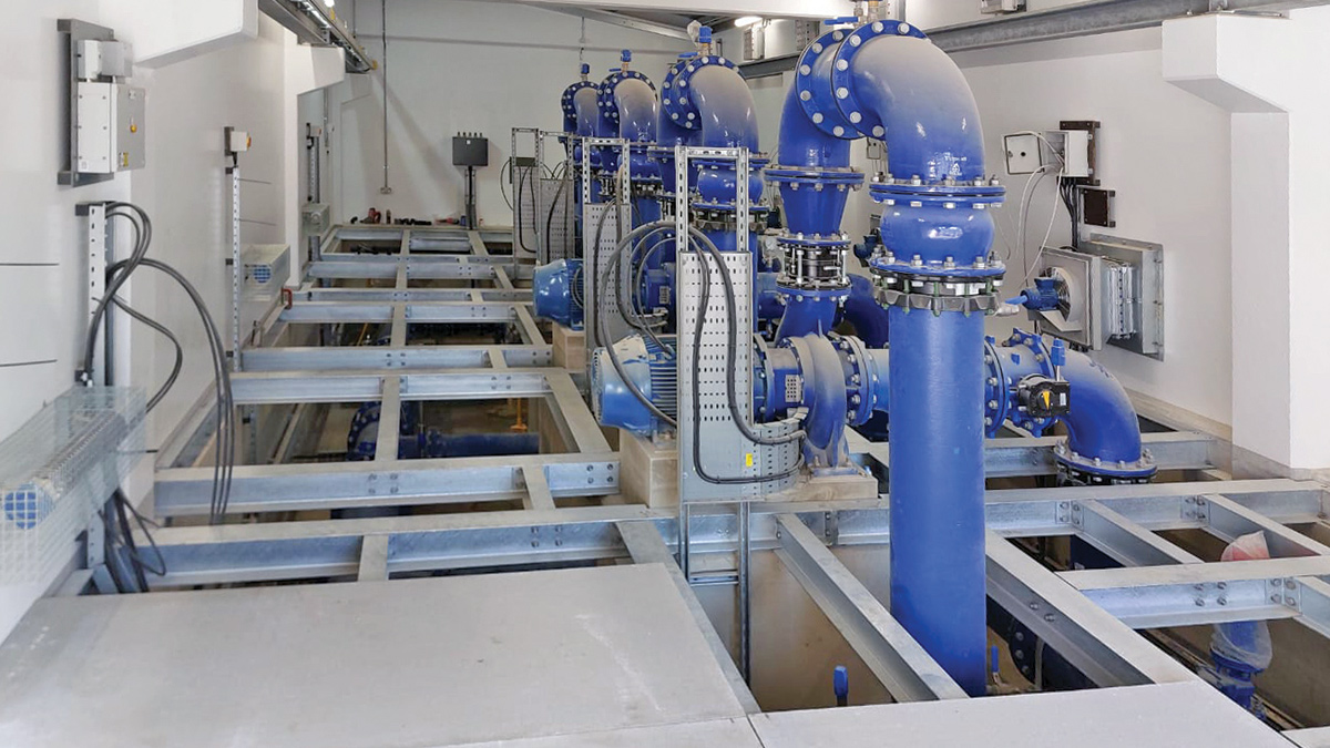
Pipework installation in basement – Courtesy of Ward & Burke
Hydraulic design
Early-stage design calculations conducted by Stantec UK were carried out to determine the different operation regimes of the network, and the associated head/flow rates required at the new Middle Aston Water Booster Station. Building upon this, Ward & Burke developed the detailed design of the pumps and internal pipework arrangement to suitably deliver the necessary operating regimes.
This led to the provision of pairs of 30 kW and 7.5 kW pumps in a duty/standby arrangement, with an actuated valve controlled bypass. The combination of the larger/smaller pumps enables efficient operation of the pumps over all of the operating regimes, which have a broad range of head requirements from the pumps.
A surge analysis was conducted by Hydraulic Analysis Ltd to assess the pressure transients in the network during operation, confirming that additional surge protection was not required in the network following the introduction of the new pumping station.
Site design & sustainable drainage
Planning permission for the new WBS was obtained by TWUL prior to Ward & Burke’s involvement, which allowed for the construction of a cladded ‘barn’ style building 8m wide x 18m long; divided into a pump hall and an MCC room. The roof level of the building approved within the planning permission was low relative to the adjacent access road and existing levels in the area, to prevent the visual impact of the building such that it was entirely screened from view by the surrounding plantings.
During the detailed design of the site, it was recognised that it would not be practical to provide vehicle access to the south side of the building bordering the access road (as required for maintenance) with the proposed access route approved in the planning permission. To overcome this, Ward & Burke revised the site layout to provide access to the west of the site boundary situated at higher level, allowing for a more gradual access road which could follow the natural gradient of the site which slopes steeply from west to east. The level difference between the road at the south of the site and the desired level of the new road to access the south side of the building was then managed with precast retaining walls (supplied by FP McCann Ltd) to maximise the accessible area in front of the building.
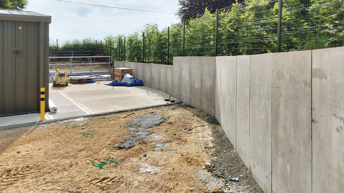
Retaining walls and screening hedges – Courtesy of Ward & Burke
As part of this redesign, a significant increase in hardstanding area was introduced to the site, leading to new considerations for the site drainage. Originally, it was intended that the drainage from the new WBS building and surrounding hardstanding would be served by a single soakaway, due to favourable sandy ground conditions at the site. Following the increase in hardstanding area, the size of soakaway required to serve the entire site became no longer practical to fit within the site boundary.
To resolve this, the site drainage was redesigned such that only the catchment area of the building and a small bunded hardstanding for fuel delivery to a standby generator would pass to the soakaway, and all other new hardstanding would be provided by permeable asphalt. Due to the potential for spills when refuelling the backup generator, the drainage from this hardstanding is passed through an oil interceptor prior to the tie-in to the soakaway.
Using the soil infiltration rates determined by on site testing to design the soakaway, it was determined that a permeable asphalt road with a thin, Type 4/20 stone subbase would provide sufficient infiltration/storage to prevent the roads from surcharging for the critical design rainfall.
The depth of subbase required was minimised by utilising CellWeb TRP from Geosynthetics Ltd, a cellular root-protection system which provides additional reinforcement to the sub-base allowing for a reduction is thickness when compared with the Thames Water asset standard road detail. This provided a significant material (and therefore cost/embodied CO2) saving, as well a reduction in excavation depth (and therefore man-hours and muckaway) required to construct the road.
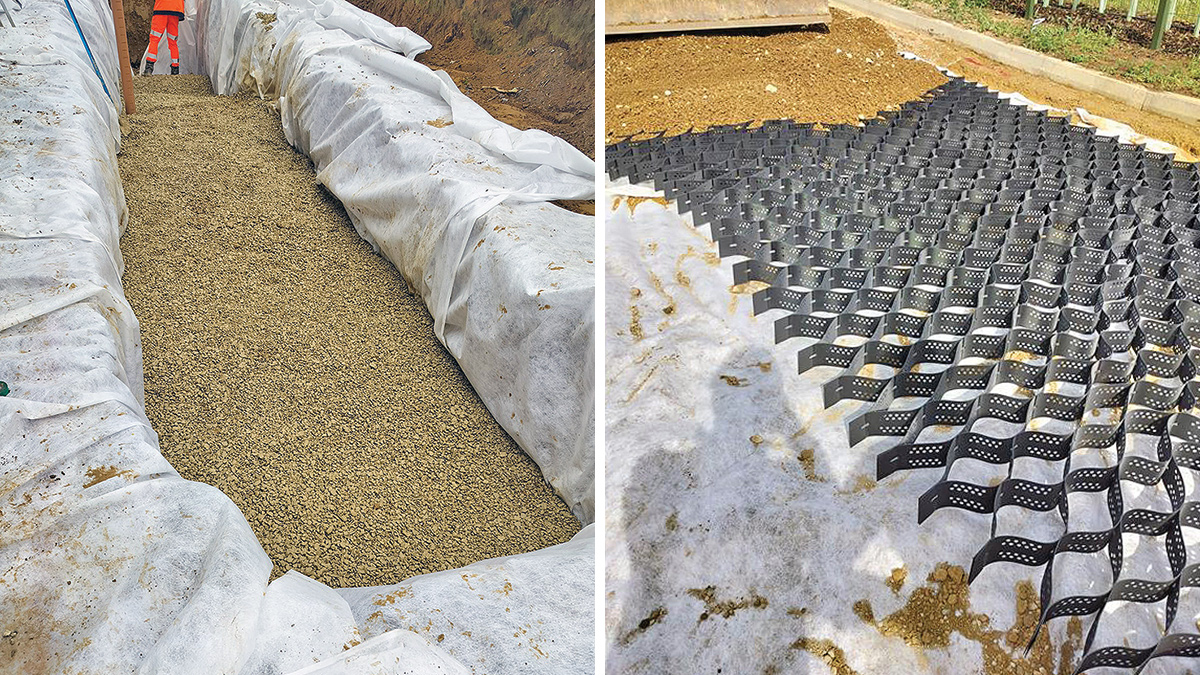
(left) Soakaway installation and (right) CellWeb installation – Courtesy of Ward & Burke
Overall, the revised design approach enabled the required access to the building to be maintained whilst keeping to the original planning levels of the building and continuing to provide self-sufficient drainage for the entire site. By meeting the above criteria, the project was able to obtain updated planning approval via a non-material amendment, which is a much faster process than submitting a new application that would be necessitated by attempting to adjust the levels of the building to better align with the existing road level and site ground level.
Middle Aston WBS Supply chain – key participants
- Client: Thames Water
- Main designer & contractor: Ward & Burke
- Design calculations for flow rates: Stantec UK
- Surge analysis: Hydraulic Analysis Ltd
- Noise assessments: AtkinsRéalis
- Project handover documentation: 3rd Light Media
- Precast building superstructure: Shay Murtagh Precast Ltd
- CellWeb TRP road sub-base: Geosynthetics Ltd
- Road access precast retaining walls: FP McCann Ltd
- Cladding installation: Owen Fabrications Ltd
- Oil interceptor, steel & cladding: Kingspan Klargester
- Building ventilation: Air Technology Systems
- Electrical installation: LDC Electrics Ltd
- MCC: Ward & Burke
- DI pipework: Electrosteel Castings (UK) Ltd
- Pumps: Xylem Water Solutions
- Pumping hall gantry crane: Bramley Engineering (Lifting Gear) Ltd
- Valves: AVK UK Ltd
- Security rated doors: Technocover Ltd
- Lightning protection: Bailey International
Building design & construction
The WBS building consists of a pump hall and an MCC room, with a roller shutter door to the south side of site to allow vehicular access for pump maintenance/removal. A full basement foundation was designed for the building, decked out with a combined steel/GRP mezzanine flooring to provide the internal floor level. This arrangement provides both ample access to the MCC for cabling works and allowed for the entire pipework assembly to be positioned beneath the finished floor level of the pump hall.
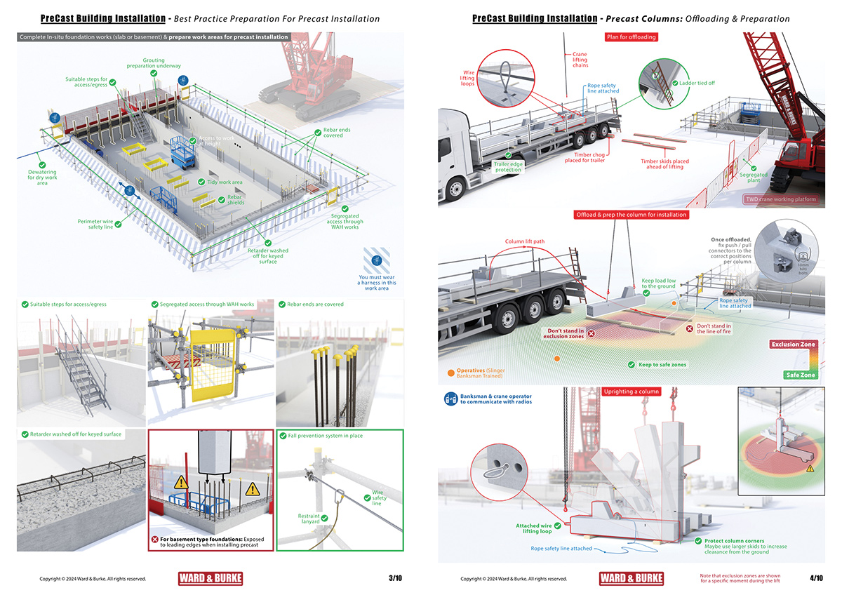
Precast installation safety- Courtesy of Ward & Burke
By lowering the pipework and instrumentation into the basement, with only the pumps mounted at the internal floor level on concrete plinths, full access to the pumps is provided with minimal pipework congestion that would otherwise necessitate alternative means of raised access, leading to issues with the available headroom fixed by the planning levels.
A range of different construction and material approaches were considered for the main superstructure of the building, balancing both the financial and embodied carbon costs for both the construction and the in service use.
Additionally, it was required that the booster station satisfies a C5 LPS 1175 Issue 8 security rating (equivalent to Issue 7 SR3). It was identified that the preferred means of achieving the required security rating with the above construction considerations was to install 3m high concrete walls enveloping the perimeter of the building.
To mitigate the risks associated with pouring 3m high walls in situ, precast concrete walls were utilised. Due to the close control of reinforcement cover and high concrete strength achieved by the precast, very thin wall panels can be used which offers savings in embodied CO2 due to reduced material volume and also elicits less onerous craneage requirements for lifting into position.
Initially a steel portal frame design was considered for the WBS, however for the size of the WBS, it was assessed that a more efficient construction sequence could be achieved by utilising concrete columns and beams all provided from the same supplier.
All precast elements were designed and supplied by Shay Murtagh Precast Ltd (from County Westmeath in Ireland), which were designed to interface with starter bars from the in situ basement foundation. This approach led to a safe, quick construction of the building super structure; in just 6 weeks. A site team of 6 workers (including a crane operator and banksman) tied the in situ foundation reinforcement, poured the foundation, and installed the completed super-structure.
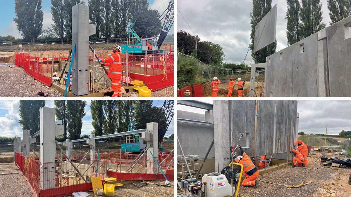
(top left) Precast column installation (bottom left) precast concrete corbels formed into columns to support, (top right) precast wall installation and (bottom right) ventilation openings formed into wall panels – Courtesy of Ward & Burke
There were significant Health & Safety benefits gained by moving the construction of the super-structure to an off-site DfMA solution. In particular, the work at height required was reduced to simply grouting the connections of the beams and columns which could be safely carried out from a MEWP. The exposure to wet concrete for the super-structure was reduced to just the grouted connections between the precast and in situ base/other precast elements, which also required fewer concrete wagons through the small local roadways which provide access to the site.
To clearly communicate the residual risks on site to the ground workers, detailed construction graphics were produced which detailed the exact construction sequence drawn specifically for the WBS, with each residual construction risk clearly identified.
Additionally, building elements were detailed into the concrete structural elements to reduce additional works wherever possible. For example, gantry crane support corbels were formed into the columns to reduce the support steelwork required for the gantry crane in the pump hall, designed and supplied by Bramley Engineering (Lifting Gear) Ltd.
A rebate was formed in the top of basement wall and pump support plinths to support the steelwork for the mezzanine floor to eliminate the requirement for support columns throughout the basement. Openings in the walls were provided to receive ventilation louvres, with ventilation being a key consideration due to the significant heat output of the pump motors and associated VSDs within the MCC. The site is located adjacent to a residential house, and to ensure that the building would not be disruptively loud during operation, a noise assessment was carried out by AtkinsRéalis.
Mezzanine flooring above basement – Courtesy of Ward & Burke
This assessment informed that acoustic louvres were required on the east of the site to prevent the noise from exceeding ambient levels at the neighbouring residential property. As a friendly gesture, TW invited the neighbouring residents to choose the colour of the building cladding, with their chosen colour being implemented.
Electrical
A new MCC with ICA section was designed and built in-house at Ward & Burke, with the electrical installation carried out by LDC Electrics Ltd.
The MCC is situated in a dedicated MCC room which is separated from the pump hall by a dividing wall. The provision of a full size basement foundation greatly aides the electrical installation works and yields a neat and tidy bottom entry into the MCC. The relevant operational regimes of the WBS are controlled by the head readings from common inlet and outlet pressure transducers.
The common outlet transducer is used to infer the top water level in Duns Tew Reservoir, while the appropriate selection of the 30 kW and/or 7.5 kW pumps is inferred from the head available at the inlet as read by the common inlet pressure transducer. The delivery flow rate is monitored by the common outlet flow meter.
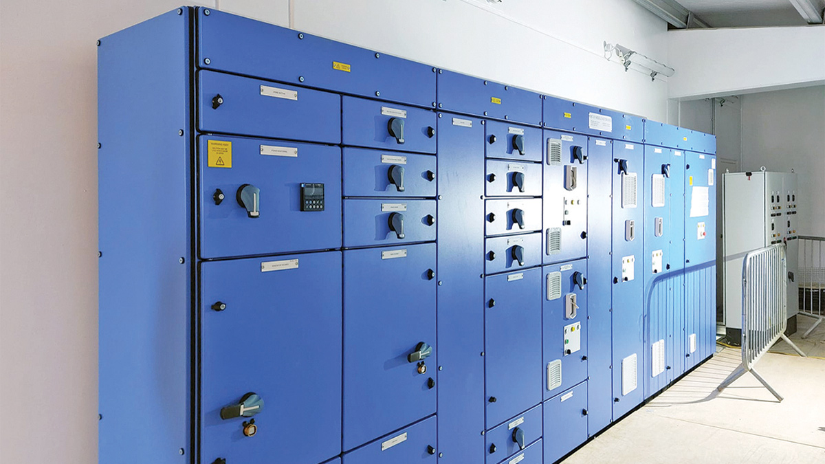
New MCC designed, built and commissioned by Ward & Burke – Courtesy of Ward & Burke
Status & summary
Ward & Burke commenced the on-site works in August 2024, and the new booster station is currently undergoing its commissioning and final completion of the minor ancillary civil engineering and road construction works.
The project is due to be handed over to Thames Water in October 2025, from when the new Middle Aston WBS will provide added resilience to the supply network for years to come