North London Heat & Power Sewer Diversion (2022)
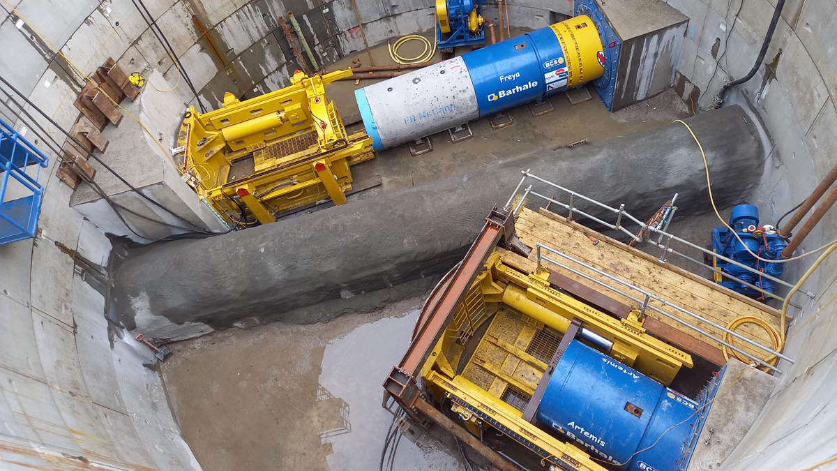
Simultaneous pipejacking - Courtesy of Barhale & North London Waste Authority
The North London Heat & Power Project is a ten-year, £1.2 billion programme to replace the current Edmonton energy from waste facility. It is being constructed on behalf of North London Waste Authority at the Edmonton EcoPark and includes a world-class Energy Recovery Facility (ERF), to generate energy from waste in the form of heat and power, and a Resource Recovery Facility (RRF), to process bulky waste and prepare the materials for energy recovery. When complete it will deal with up to 700,000 tonnes of waste from the seven north London boroughs every year and will generate around 78 megawatts of electricity – enough to power around 127,000 homes. Additionally, the project will incorporate a reuse and recycling centre for the public and a community hub and visitor centre called EcoPark House.
Sewer diversions
Following site clearance and demolition works, the lead contractor for the EcoPark South works, began piling to prepare the site for the main structure of the RRF. It used a construction technique combining continuous flight auger piling, controlled modulus columns and a low permeability Trenchmix.
A significant obstacle to progress was the presence of two Thames Water foul water sewers, the Angel Sewer and the Chingford Sewer, running beneath the southern part of the EcoPark.
Barhale was appointed to undertake complex engineering works to divert the two sewers a challenge described at the pre-start meeting with the authority as the key to unlocking the site for the entire facility.
The sewer diversions had the potential to create a significant bottleneck for the entire project and from the offset, the Barhale design team looked to measures which could accelerate not only the delivery of their solution but also could allow the subsequent works programme to start early.
During the design phase, Barhale identified an opportunity for a tunnel drive shaft design which would allow the highly unusual step of launching two pipe jacks from a single shaft simultaneously to fast-track the programme of works.
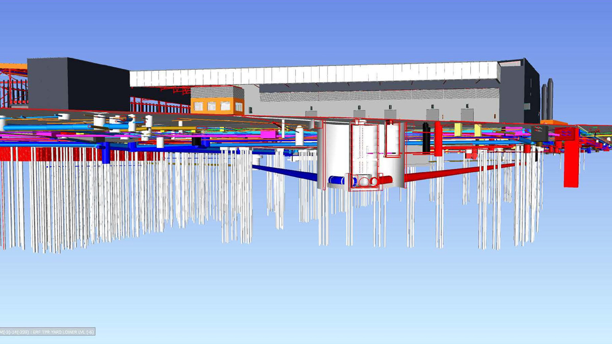
3D model of 1200mm tunnel lines and RRF pile layout – Courtesy of Barhale & North London Waste Authority
Shaft construction
The sewer scheme includes a main drive Shaft A, which consists of a 12.5m precast segment shaft that Barhale constructed to enable the tunnelling. The two reception shafts south-east and south-west of the drive shaft, respectively, are known as manhole B, a 6m diameter segmented shaft, and Manhole C1, a 4.5m segmented shaft.
The tunnel drives run approximately 140m from Shaft A to Shaft B and 210m from Shaft A to Manhole C1. In addition, a final connection needed to be driven from Manhole C1 to an existing manhole further south. This was a 450mm guided auger connection, also completed with trenchless technology.
The shaft for Manhole B was installed using underpinning and saw a pre-driven cofferdam constructed from sheet piles driven to a depth of about 7m. A ring beam was installed and the shaft underpinned – effectively hanging the segments underneath each other; rather than jacking down to formation. It was to decided to construct the shaft in this manner because two heating network pipes ran over the top of the shaft which were an element of future works on the project.
The original location of Manhole C was in the middle of where three working areas on the EcoPark met. This included major civil works for a district heating scheme for 10,000 homes being built in the area as part of a Meridian Water development. This presented a coordination problem: having different principal contractors working in very close proximity, with a very narrow opportunity for access. It also introduced a layer of technical risk and created productivity and health and safety concerns.
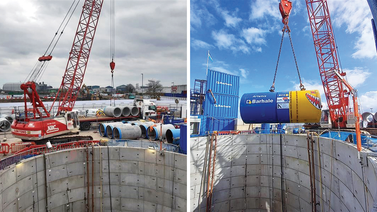
(left) Ground level works and (right) lowering the TBM into Shaft A and preparation for drive – Courtesy of Barhale & North London Waste Authority
The Barhale design team dealt with the challenge relating to the location of the original Manhole C, by moving it to a new location approximately 50 meters to the south west under the name C1. This required significant additional design in a heavily time constrained project.
Given that the originals were large diameter sewers laid over a considerable distance, they had been built quite unusually whereby a timber arched head had been constructed with the concrete pipes laid within.
Over pumping was handled by a combination of four 8” Hydrainer slurry pumps with a pumping capacity of circa 600 litres/second.
Ground conditions
Ground investigations across the sewer alignment, had shown the geological cross section comprised made ground, above alluvium, Kempton Park gravel, the London Clay band (where the tunnel line was set) and then the Lambeth Group.
A particular risk was the presence of different water tables. There was an upper and lower aquifer, and one of the design and construction constraints was that migration of water had to be prevented between the upper and lower aquifers. This was inspected during the excavation of Shaft A and showed that the water tables were fully sealed off and there was no migration.
NLHP Sewer Diversions: Supply chain – key participants
- Design & build contractor: Barhale Ltd
- Design: OTB Engineering
- Steelwork fabrication: BCS Group
- Shaft segments & jacking pipe bend: FP McCann
- Cofferdam sheet piling: Fussey Piling
- Dewatering & boreholes: Stuart Wells Ltd
- Tunnel boring machines: Iseki
- Over pumping: Hydrainer Pumps
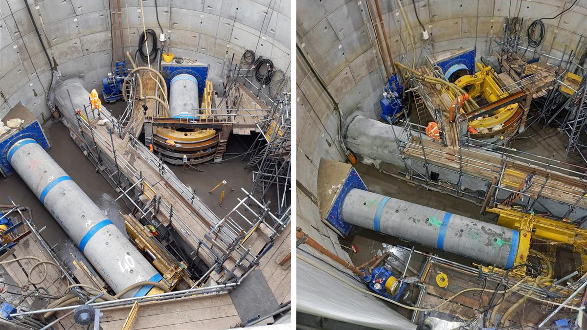
Shaft A dual drive setup – Courtesy of Barhale & North London Waste Authority
The pipe jacking
The conditions for dual pipe jacking are very rare because projects do not usually have two connections to one shaft but rather proceed in a linear fashion.
Even when the circumstances are right, the technical challenges have historically discouraged attempts. However, because of the project’s tight timeframe and the time benefits that could accrue to future elements of the North London Heat & Power Project, Barhale believed that the additional operational complexity that would come from launching simultaneous pipe jacking for the sewer diversion was a price worth paying.
There were challenges: first, the main shaft had to be constructed with a live sewer running through its middle, severely constraining working space; second it would be essential to design the temporary works so that the thrust force of the pipejacking operations on the shaft and on the live sewer would be minimised.
It required a creative solution beyond the standard installation of a back wall to protect the structures and to give sufficient thrust reaction to achieve predicted output.
Barhale’s team collaborated with engineers from BCS Group to design and fabricate a bespoke metal frame to suit the existing jacking unit with a jacking capacity of 500 tonnes.
Assembled in situ and mounted direct to the shaft base slab, it was compact enough to fit within the tight space available between the shaft and the running sewer.
A dry spray concrete system was used to protect the existing sewer.
The tunnelling was carried out using two 15t Iseki 1200 tunnel boring machines measuring 4.25.2m long and 1.5m wide and named Freya and Artemis. The close proximity of the live sewer meant that the rig required constant monitoring but there was minimal movement throughout the tunnelling.
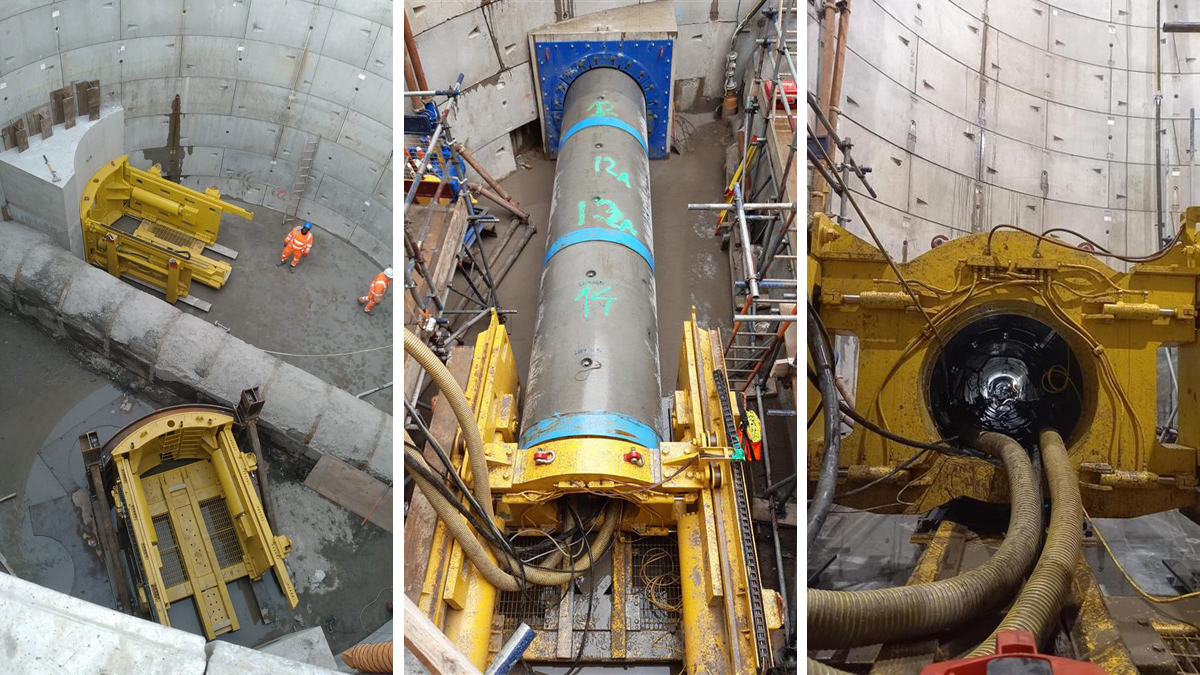
(left) Jacking rigs and (middle/right) Shaft A to Shaft B drive – Courtesy of Barhale & North London Waste Authority
Conclusion
The dual pipe jack was successfully completed in ten days enabling an important programme saving for the client. The manpower requirements were reduced as the same team could manage tasks across the two pipejacking operations and items such as slurry and lubrication management were automated.
There were carbon savings on multiple fronts. Idle time for the shared equipment such as separation plant, crane, excavators, generators and pumps was dramatically reduced, and diesel consumption was halved. The amount of water used during the slurry recycling process was estimated to be between 50% and 60% less than if the pipe jacks were consecutive.
The successful use of simultaneous pipe jacks cleared a programme bottleneck ahead of schedule, creating the opportunity for subsequent works to start on site early. While it offered a great engineering challenge, it delivered against all the operational goals and the bespoke jacking rig provided an innovative breakthrough for future application.


