Nottingham, Shakespeare Street, Flood Alleviation (2020)
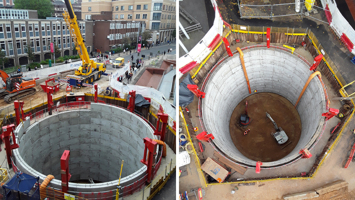
(left) Shakespeare Street shaft viewed from Dryden Street and (right) approaching the base formation level - Courtesy of nmcn PLC (now Galliford Try)
Shakespeare Street in Nottingham is situated at the heart of Nottingham Trent University campus, a short walk from the main square in the city centre. The basements of a number of buildings in the area suffered repeat sewer flooding, ranking inside the top 1% of all flood risks across the Severn Trent (ST) region. In response, ST promoted the Nottingham Shakespeare Street Flood Alleviation Scheme to address the internal, external and highway flooding risks. The city centre location which is densely urbanised with very little open space in the immediate vicinity posed a significant challenge to the project team. Furthermore, being situated in the middle of the campus just 150m from the Student Union and in close proximity to historic and listed buildings meant the sensitivity of the project was high and unavoidably in the public eye.
Stage 1
Stage 1 of the project involved ST undertaking investigations to understand the flooding mechanism including CCTV and manhole surveys, flow surveys and rain monitoring and EA water maps were studied which all allowed a hydraulic model of the complex urban catchment to be built and verified. The existing sewer serving Shakespeare Street itself is a 1.5m tall x 1m wide Victorian built brick egg combined sewer conveying a large amount of flow from the north east of the city centre down through the town. The sewer was designed to fill to its top level where it has most capacity, but new low-level basement connections being made onto the network over the years mean the system had very little freeboard available above the soffit of the sewer. Growth in the large catchment means that in heavy rain the hydraulic level rises above the critical point causing internal flooding.
Following extensive feasibility investigations on the project, Severn Trent appointed nmcn PLC (now Galliford Try) under the AMP6 Design and Build Framework to deliver the project with a target completion date before the end of the current Asset Management Plan period, delivering much needed relief to the area.
Engaging stakeholders
The flooding mechanism dictated the storage location in a busy city environment which is in the centre of a number of Nottingham Trent University (NTU) buildings. Whichever option was chosen would more than likely require the closure of Shakespeare Street. It soon became apparent that ST, nmcn, NTU and Nottingham City Council (NCC) would have to work closely together to coordinate the works if the project was to be successful. To this end, planning and stakeholder engagement throughout was of paramount importance which led nmcn to set up and facilitate weekly coordination meetings with all the main parties during the design, planning and construction phase of the project. This proved to be invaluable in communicating with and gaining the support of the university estates department.
Good communications and negotiations were essential to be able to enable the most efficient storage solution for the scheme. It was identified that the initially promoted solution of a new offline 180m long x 2.8m diameter tunnel along Shakespeare Street accessed by shafts approximately 8m deep at either end, and with an intermediate shaft midway along, was potentially not the most effective. The only available open space in the immediate area which would be viable as a location for a shaft was a space owned by NTU that had been relatively recently upgraded with trees, planters and benches to create a seating area. There was also the added consideration that the area was earmarked for possible future development use. Numerous meetings were held between ST, nmcn and NTU to explain the constraints that the scheme faced and why the plot of land had been selected in order to balance conflicting desires and gain their support for the project.
From the early stages of the project and initial stakeholder engagement effective project management has been essential. The sensitive location combined with the heavy, disruptive engineering have meant that the impact is all too real for the people around us. In particular, the construction work is unavoidably in the public eye at the heart of a busy university campus. The impact on the university was at the forefront of the project team’s minds throughout the planning and execution of the project with the aim to keep disruption to the minimum possible. This included arranging the construction phasing dates around the university summer graduation dates, as well as suspending work for a week in December for the winter graduations. Furthermore, operations being undertaken during the clearing period were sequenced to avoid breaking ground to prevent any potential telecommunications disturbance in this important time for the University.
Nottingham, Shakespeare Street, Flood Alleviation Scheme – Supply chain: key participants
- Client: Severn Trent
- Principal contractor: nmcn PLC
- Structural design: GHD
- Structural and temporary works design: Eastwood & Partners
- Tunnelling contractor: AMC Tunnelling
- Pipework fabricators: Portobello Engineering
- Submersible pumps supplier: Xylem Water Solutions
- Shaft segments and jacking pipes: FP McCann
- Manufacture of cover slab: Macrete
- Temporary overpumping: Hydrainer Pumps
- Motor control centre supplier: Technical Control Systems Ltd
- Scaffolding and access: Derby Access
Thinking deep
The initial notional solution was developed in collaboration between nmcn and the ST hydraulic modellers and programme engineers resulting in three potential options that could accommodate the storage requirements. Given the very limited open space available, the initial proposal to utilise a 180m long tunnel to provide the storage was discounted not only because the three shafts needed for access would have required extensive service diversions, but there were also concerns that alternative solutions could ensure safer long term maintenance for ST Operations.
These concerns led the team to change their thinking from horizontal to vertical cylindrical storage. A 17m deep by 12.5m diameter shaft tank was to be built at the end of Dryden Street, below the public highway just before it meets with Shakespeare Street, utilising the adjacent landscaped area for site compound space only to retain future development potential. By utilising the public highway at the junction, it was possible to obtain sufficient clearance to adjacent buildings. Multiple service diversions were still required, but on a much smaller scale than the other options offering a cost benefit to the project which was considered to be worthwhile. This option also provided the shortest overall programme length by maximising working area, albeit still highly restricted, therefore causing the least possible disruption to all stakeholders and the public.
Technical challenges
Although the location and outline design had now been confirmed the technical challenges for the team had only just begun. nmcn undertook extensive investigations to inform future design decisions, and progressed the detailed design of the scheme. To do so, GHD was engaged as structural design consultant to begin calculations for the shaft tank and design a bespoke weir chamber which directed flows from the existing egg-shaped sewer to enter the offline shaft tank.
Hydraulic consultants Hydrotec Ltd was employed to create a physical model of the existing sewer and proposed shaft tank and weir chamber. The maximum discharge rate to the new shaft tank was modelled at approximately 3700 l/s with spill to the overflow initiated at a continuation flow of 2700 l/s, this gave a total peak inflow to the weir chamber of 6400 l/s. The model accurately reproduced all significant full-scale hydraulic effects caused by the storm flows and was modified to make the system operate effectively. This model was then used by nmcn and GHD in order to progress and finalise the design.
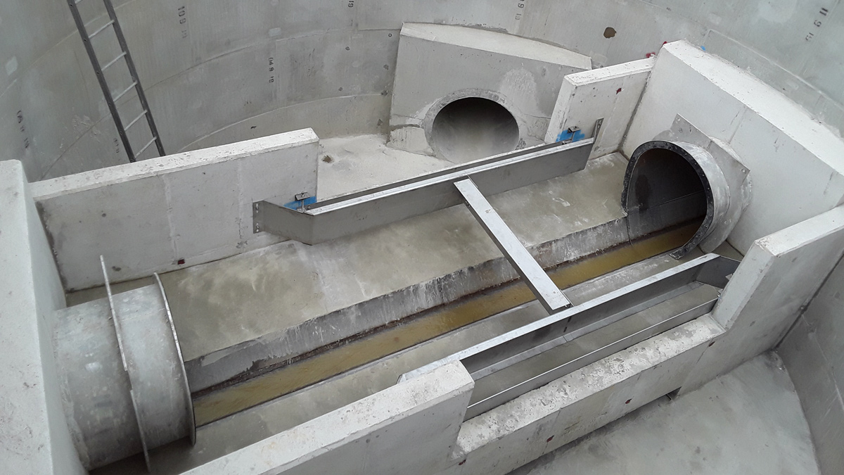
Finished weir chamber, complete with reinforced portals, weir walls and stainless steel baffle plates/scum boards – Courtesy of nmcn PLC
A bespoke piece automation software was piloted on this project by GHD, which generated detailed design options for a variety of structural forms and configurations for the shaft tank including base plug, under-ream base, jacking collar and tunnel portals. The automation software automatically generated each option as a 3D REVIT model with accompanying general arrangement drawings. This allowed GHD and nmcn to review several detailed design options and select the optimal design solution. A design suitable for the construction of a weir chamber around an existing brick egg sewer was particularly challenging requiring careful consideration of sequencing and temporary stability while maintaining sewer capacity. The 7.5m diameter x 5m deep weir chamber, designed to completely surround the existing brick sewer, comprised in situ joinery works to create the weir walls, and stainless steel longitudinal baffles installed in a dual function as flow conditioning devices and also serving as scum boards.
One of the greatest challenges for the team was how to construct the weir chamber around a live, potentially fragile sewer, and then turn flows which could be up to 6.4m3/s. The key consideration was how to keep the need to over pump existing flows to an absolute minimum to reduce the risk of pump failures, potential flooding, and excess noise in a built-up student area. To do this an innovative, bespoke, steel flume pipe was designed. This would replace the section of brick egg sewer that had to be removed in order for the weir chamber to be constructed around it guaranteeing its integrity throughout the construction. To achieve the perfect fit, a survey team carried out a confined space entry with rescue team into the existing sewer, and from that manufactured a plywood template of the egg sewer from which the bespoke flume would be fabricated.
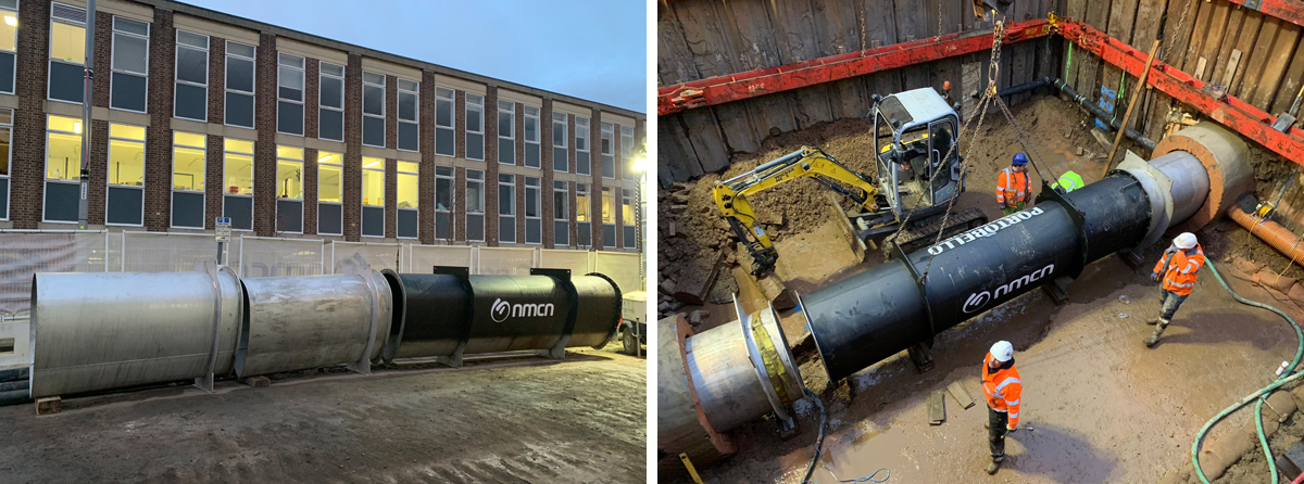
Bespoke sleeve inserts and flume for brick egg sewer, and during installation for weir chamber construction – Courtesy of nmcn PLC
Investigation and enabling
nmcn believe that site safety starts from the beginning of the design phase. To this end, detailed investigations were carried out early in the programme to establish a comprehensive map of the existing underground assets and conditions to inform the later design stages. Investigations included ground penetrating radar, trial holes and electromagnetic surveys, as well as consideration of the Nottingham cave networks and archaeological impacts.
The output of this was the confirmation of exactly what services required diversion to clear the footprint of the shaft and weir chamber. In this case, the full suite of utilities needed to be moved including medium pressure gas, HV and LV electricity, BT ducts, potable water main and the existing 900mm x 750mm brick egg sewer running down Dryden Street. It was even necessary to relocate a standalone cash machine kiosk complete with its communication cable. These service diversion works were all carried out between April and July 2019 in a race against time to complete before the Nottingham Trent University Graduations taking place in the immediate area so that there was be no visual presence on site at that time. It was also necessary to remove a number of mature trees which lined both sides of Dryden Street under an agreement with Nottingham City Council where 20 compensatory trees would be planted around the city centre.
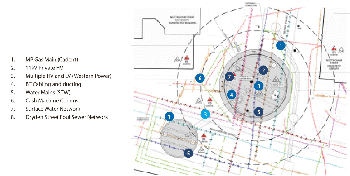
List and location of service diversions required for project – Courtesy of nmcn PLC
Constrained construction
nmcn commenced the main works in August 2019, starting with a bespoke sheeted pit cofferdam excavation which enabled construction of the 17m deep x 12.5m diameter shaft tank sunk by the traditional dry caisson method (segmental sections) and aided by 8 (No.) hydraulic jacks placed on a reinforced concrete ring beam, with a maximum jacking load of 150 kN each.
The construction of the shaft in such a tight working area was a particular challenge for the project team. Thorough planning and sequencing of the works, plant selection and materials delivery was essential so that not an inch of space was wasted. The site would be accessed from two directions, Shakespeare Street and Dryden Street, and it was even necessary for the site access from Dryden Street to run though the CDM area of an adjacent building project being undertaken by the university.
The already limited working area was stretched to the limit because the diameter of the shaft meant that the beams required for the cover slab could not be brought to site precast. This necessitated the beams being precast on site ready to be lifted into position. The 31-tonne beams and 12-piece segmental cover slab, and 4-piece weir chamber slab were lifted into place using a 250-tonne crane. This work required further road closures and weekend working.
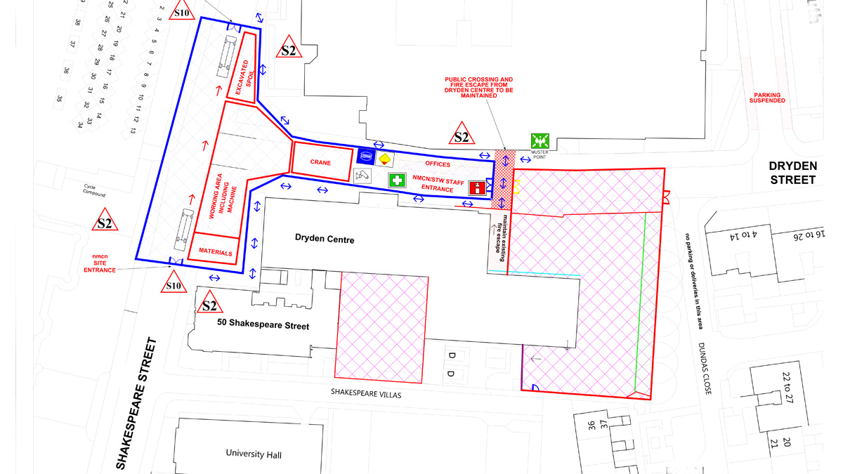
Site compound area lined in blue; adjacent CDM in red – Courtesy of nmcn PLC
As the weir chamber was to be constructed around the existing sewer, the team carefully designed and planned to ensure stability of the existing brick sewer and the stainless bespoke flume during all phases of construction. To overpump the existing sewer, and due to the potential for high storm flows, bespoke plates were designed to stank off the flow comprising a bottom fixed plate only 300mm high and a 500mm high removable top plate that could be pulled away from ground level in the event of a storm.
Due to the sensitive and individual nature of the weir chamber element of the works, the nmcn design/site team took the detailed option of carrying out a day by day collaborative plan (CP) along with representatives of Portobello Engineering who manufactured the flume pipe, Eastwood and Partners who completed the temporary works design for the flume including its support detail, Hydrainer Pumps who sized the over pumps and AMC Tunnelling who were the nmcn’s main contractor for the works. The initial plan undertaken estimated that this element of the works would take a total of 8 days, but due to careful planning and collaboration between all contractors and suppliers, the total time taken was only 4.5 days. The flume was supported by individual pull chains and steel beams situated at ground level in the temporary state. In its permanent state the sewer is supported by a series of reinforced portals to ensure its integrity.
The design for the weir chamber also had to factor in the pipe jack tunnel requirements for the spill pipe to connect both structures. This included a bespoke pipe jack hydraulic ram arrangement and temporary reinforced back wall for the pipe jack to thrust and jack against. To enable the flume installation, temporary over pumping was required to install a bespoke weir plate fixed in the upstream manhole. To connect the concrete pipe jack and the drop pipe within the shaft tank, an individual transition flange and plate arrangement was designed and fixed to the shaft tank wall against a further reinforced concrete portal to enable the installation of the 1.2m diameter bespoke one-piece stainless steel inlet drop pipe.
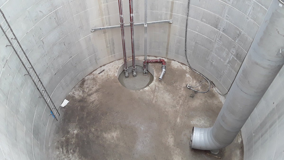
Shaft tank mechanical installation – Courtesy of nmcn PLC
Mechanical and electrical installation
The mechanical and electrical works included the installation of a new GRP kiosk containing the new ST framework (shaft tank) motor control centre (MCC). The MCC controls two duty/standby 13.5 kW submersible pumps located within the shaft tank, plus a 13.5 kW hydroejector pump, designed to maintain suspended solids with the stored storm water. The two pumps enable the contents of the shaft tank to be pumped back into the existing sewer on Dryden Street, which will then gravitate to the existing Shakespeare Street brick egg sewer further downstream. An ultrasonic level sensor acting as an ‘inhibit’ signal has been installed in a downstream manhole on Shakespeare Street, once the level in this sewer has subsided low enough the duty/standby pumps will activate to empty the shaft tank with a peak flow rate of 92 litres per second.
Conclusion
The project successfully delivered the required flooding benefits on time and Shakespeare Street and Dryden Street were reopened in May 2020.


