Scaynes Hill WwTW (2019)
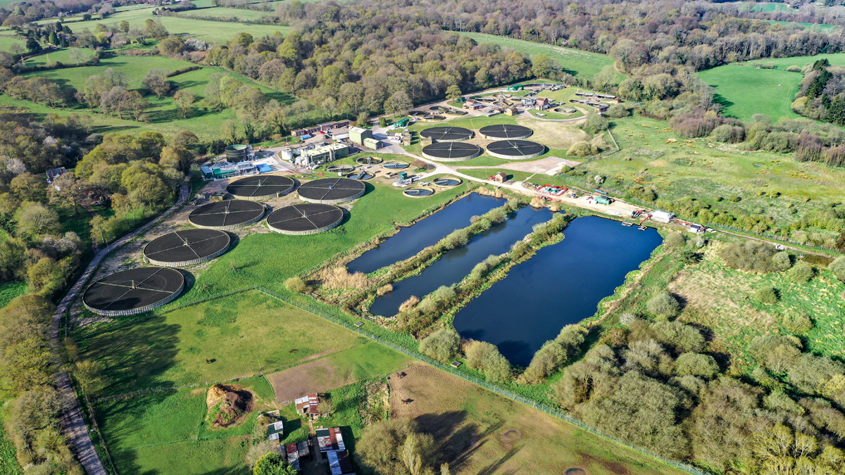
Aerial view of Scaynes Hill WwTW - Courtesy of Southern Water
Scaynes Hill Wastewater Treatment Works serves a population of approximately 38,000 from Haywards Heath and surrounding areas in West Sussex, with capacity to treat up to 337 l/s of incoming wastewater flow. The treatment works also receives imported cess via tanker from customers not connected to the mains drainage system, plus liquid sludge via tanker from small rural treatments works in surrounding areas. Cess is treated within the main treatment stream, whilst sludge is mixed and processed with sludge produced by the main treatment processes.
Project overview
In December 2014, Southern Water initiated an AMP6 project to upgrade the site, in response to tighter limits imposed by the Environment Agency (EA) on the concentration of phosphorus and iron within the treated effluent. The new limits became effective in November 2018, as part of the EA’s National Environmental Programme.
The upgrade also included modifications to the existing sludge processing facilities, ensuring there was sufficient capacity to meet current and projected needs to the year 2025.
The delivery of this project followed Southern Water’s collaborative model, with in-house project managers and engineers working closely with external consultants (strategic solution partners) and contractors (delivery partners). Through this joined-up approach, Southern Water’s project team was able to deliver a solution to meet new EA permit requirements within tight budgetary constraints.
Background
The previous EA discharge permit did not include an upper limit of phosphorus concentrations. The new EA permit required that from November 2018 the works do not exceed a concentration of 2 mg/l of phosphorus, measured as an annual average.
Prior to upgrade work, the wastewater treatment process consisted of 6mm aperture screens, cross flow detritors, an intermediate Archimedean screw pumping station, 8 (No.) primary settlement tanks, 10 (No.) biological trickling filters, 6 (No.) humus settlement tanks and 3 (No.) final stage polishing lagoons. The lagoons acted as a final polishing stage of the treatment process, but due to their size and location, they were difficult to empty and maintain. However, an early requirement of the scheme was to isolate the lagoons from the treatment process, leaving the lagoons to continue as a habitat for waterfowl and other wildlife.
The sludge processing stream consisted of a single trailer mounted centrifuge, producing sludge cake to 25% dry solids (DS). The dewatered sludge was then transported to a regional sludge processing centre for final processing via digestion, allowing for the production of biogas and on-site generation of electricity and heat via gas engines.
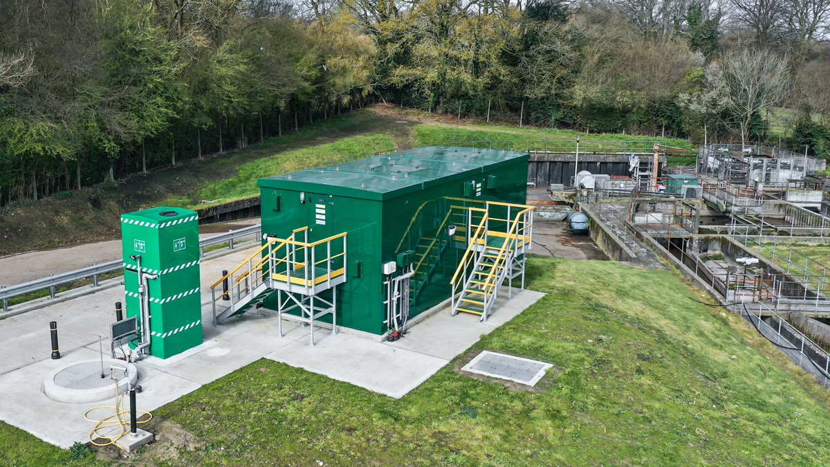
Ferric dosing kiosk delivery area – Courtesy of Southern Water
Project delivery
The delivery route for the project followed Southern Water’s standard AMP6 format, with Southern Water’s in-house engineers working collaboratively with the Strategic Services Partner (SSP) Stantec UK – under the Engineering and Technical Solutions (ETS) banner – to produce process design and outline engineering design.
The construction delivery partner for the project was CMDP, a joint venture between Costain and MWH Treatment. CMDP also provided support during the outline design stage, providing advice and guidance on constructability, construction costs and risks.
Design
To ensure the works would meet the new phosphorus consent, the ETS process design engineers identified the need to enhance the performance of the existing primary settlement tanks treatment through dosing with ferric chloride. The ferric ions trigger the precipitation of inorganic forms of phosphate and settle with the primary sludge.
Additionally, with a need to isolate the existing lagoons whilst ensuring consistent final stage settlement performance, it was identified that two additional 14.9m diameter humus settlement tanks were required.
Investigations into ground conditions were undertaken during the outline design stage, requiring cable percussion boreholes to a depth of 9m (standpipes installed within the boreholes), inspection pits, resistivity tests, dynamic probe holes to a depth of 8m and permeability tests.
The borehole logs revealed topsoil across the site was underlain with made ground, river terrace deposits/weathered bedrock, Upper Grinstead Clay and Cuckfield Stone Beds. The Cuckfield Stone Beds transitioned from the overlying clays, through silty sand to sandstone at the end of the borehole.
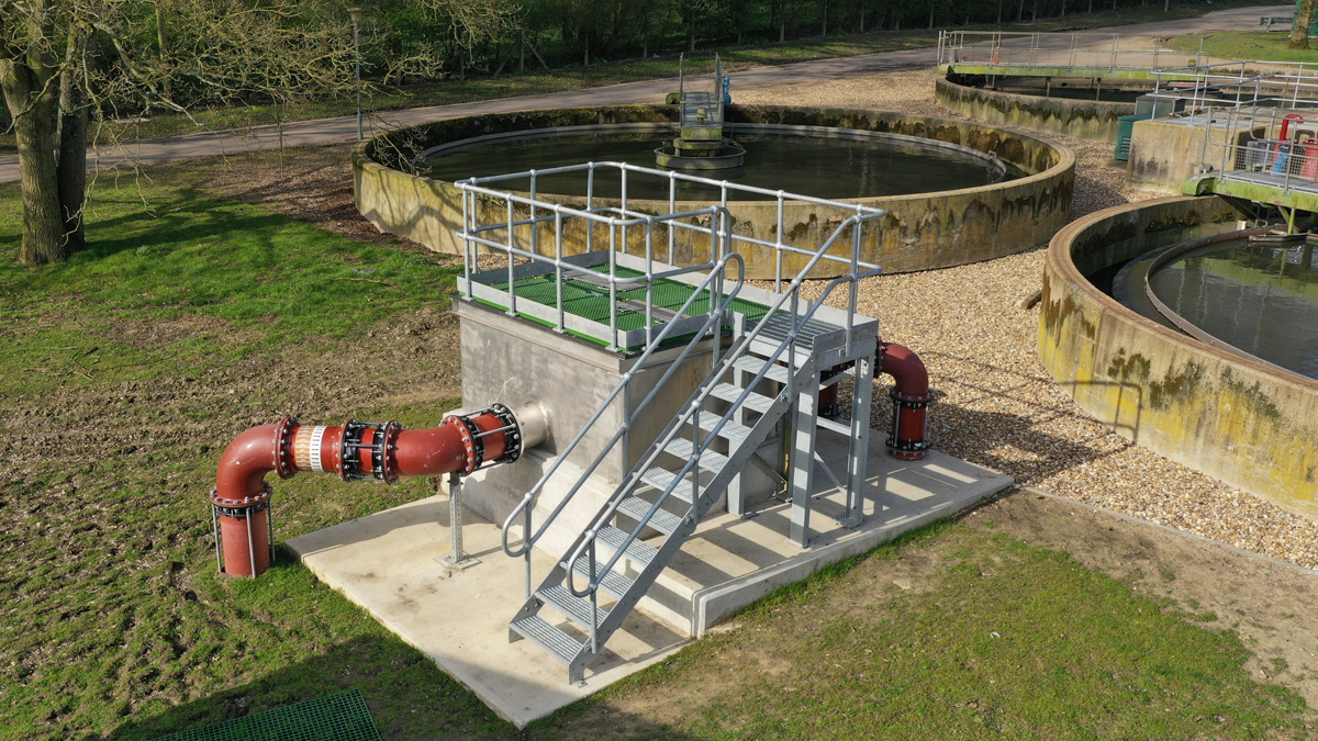
Humus flow split chamber (converted tanks to the rear) – Courtesy of Southern Water
The outline design identified the need for two additional humus settlement tanks of a similar size to the existing ones. These additional humus tanks were to be aligned with the existing hydraulic gradient and tank water levels, with overall depths of excavations during construction down to a depth of between 5-6m.
However, with the risk of running sand within deep excavations, the close proximity of existing structures, and the foreseen problems with dewatering the ground, the cost and associated risks of constructing these two tanks exceeded the budgeted funding allowance and risk tolerances.
To ensure the objectives of the project were still going to be met, Southern Water arranged for a number of collaborative workshops to be undertaken. These brought together the ETS design team, the CMDP construction team, the Southern Water Operations team and other in-house stakeholders. These workshops employed a methodology called Systematic Inventive Thinking, to trigger innovation and problem solving.
The workshops enabled alternative solutions and modifications in the way the project could be delivered to be identified, all with the aim of reducing time, costs and risks.
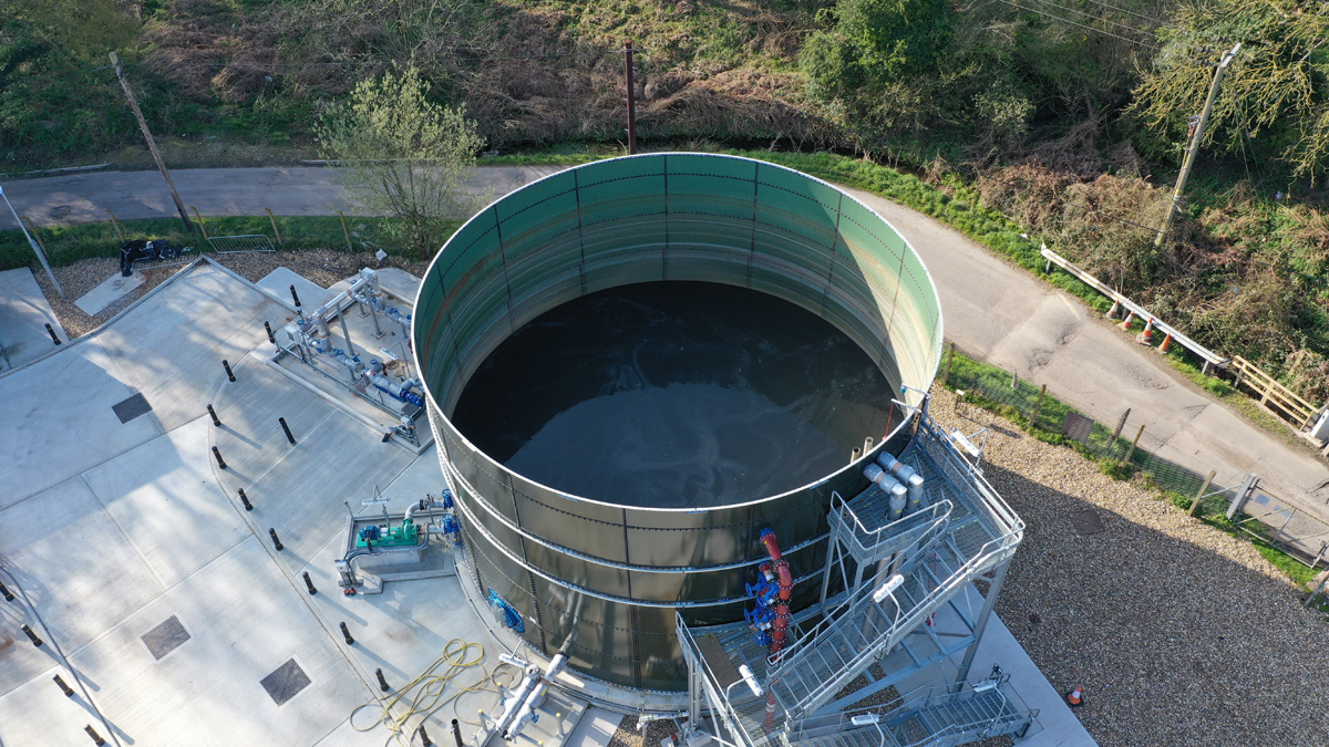
Sludge storage tank – Courtesy of Southern Water
Alternative solutions were subsequently appraised on capital cost, whole life cost and risk score.
One of the techniques employed by the Systematic Inventive Thinking was subtraction, where an essential component of the solution was removed – in this instance, new humus tanks.
After discussion and review, it was agreed that with the provision of a new intermediate submersible pumping station, two of the existing primary settlement tanks could be disconnected from the primary treatment stream and modified to receive a proportion of the trickling filter effluent, therefore providing the required additional humus settlement capacity. Although excavation would be required for the new intermediate pumping station, the pumping station wet well structure could be sunk as a caisson, avoiding extensive temporary works and groundwater control.
In addition to this, challenges were made to Southern Water’s specifications where relaxations in these standards could be used to reduce costs without adversely affecting risk.
Scope of work
Main treatment stream
Following conclusion of the Systematic Inventive Thinking process, the agreed scope of work for the main treatment stream comprised:
- Conversion of two previously out of use 13.6m diameter primary settlement tanks to humus tanks.
- Modifications to flow splitting chambers to reflect changes to primary settlement capacity and humus settlement capacity.
- Ferric chloride dosing facility to enhance primary settlement solids removal.
- Alkalinity correction (dosing sodium hydroxide) to counter the effects of the ferric chloride.
- New humus tank feed pumping station and pipelines.
- Isolation of the lagoons from treatment process and the final effluent discharge outfall.
- Real time pH monitoring.
Sludge treatment stream
The agreed sludge treatment stream scope comprised the following prime components:
- Glass coated steel sludge storage tank: 700m3 capacity, complete with sludge mixing.
- 2 (No.) centrifuges each providing capacity for 24.7m3/h of sludge at 3% dry solids, dewatering to 25% dry solids.
- Progressive cavity pumps for pumping liquid sludge and sludge cake.
- 4 (No.) sludge cake bin bays with load cells and traffic light indicators for bin full/empty status.
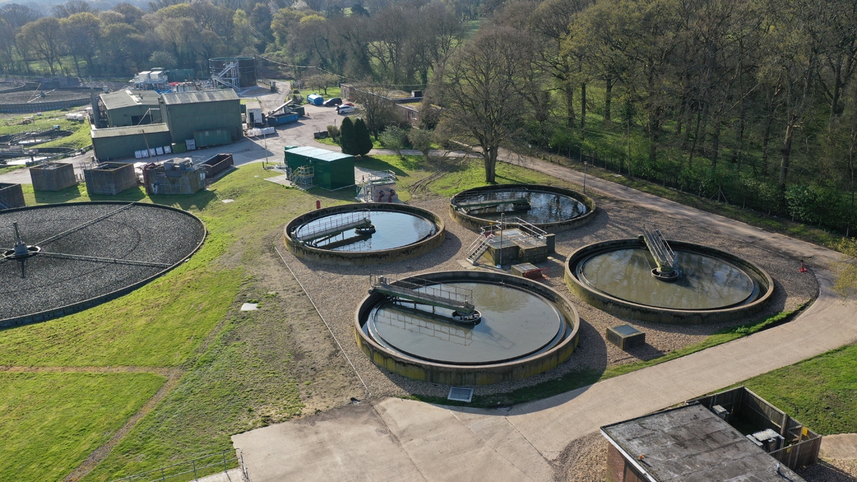
Two existing PSTs converted to humus settlement tanks – Courtesy of Southern Water
Construction and delivery
CMDP was appointed as principal contractor in October 2015. Detailed design commenced April 2017, with work on site beginning in July 2017 to deliver the project under Southern Water’s AMP6 capital investment programme.
From the outset, collaborative planning boards were used to ensure all those involved in supply and delivery chain were mapping out current and next steps around four months in advance. Key aspects of construction were:
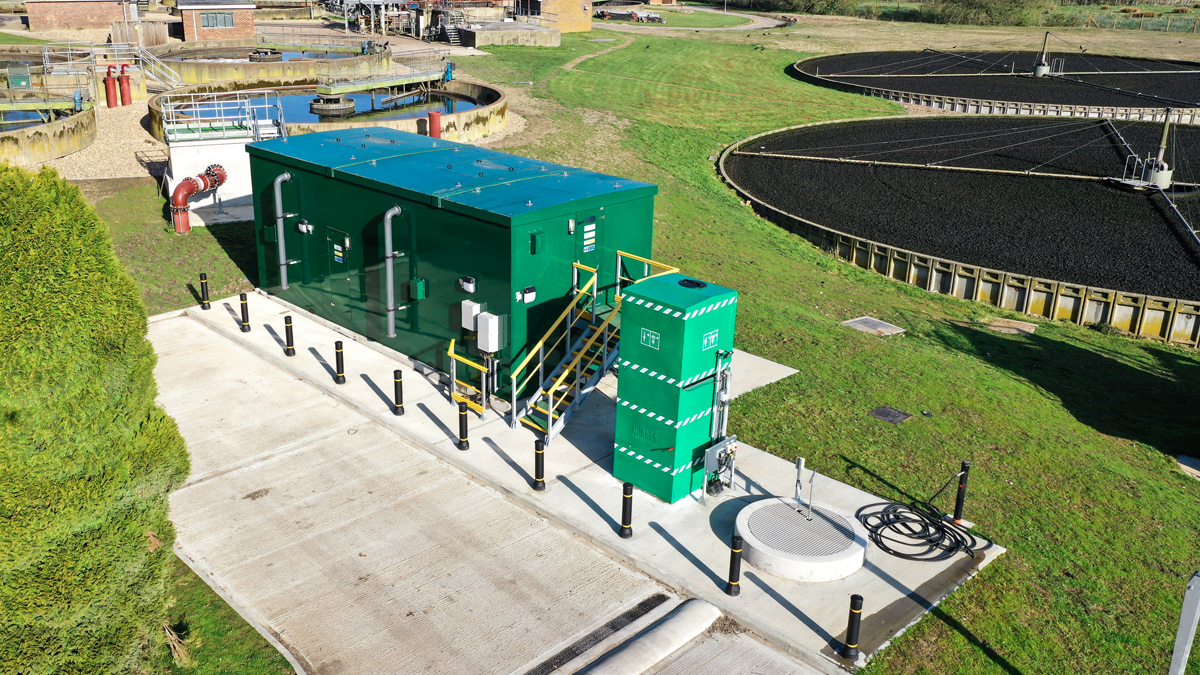
Alkalinity dosing kiosk delivery area – Courtesy of Southern Water
Ferric and alkalinity dosing areas: The civil structures forming the base slabs, bunded delivery areas and below ground pipework were relatively straightforward to construct. However, the biggest challenge came with delivering the chemical dosing kiosks to the site, which is accessible only by a 0.75 mile tree-lined track from Sloop Lane, an unclassified road. With each kiosk measuring approximately 9m in length, 4m in height and 4.5m wide, a significant amount of preparation was required to ensure a successful delivery. Ecologists surveyed the site for bats and nesting birds, prior to the felling of some trees and the removal of Armco barriers and neighbours’ fencing, which was later reinstated.
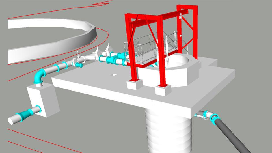
Humus pumping station 3D CAD model – Courtesy of Southern Water
Humus pumping station: The humus pumping station is located in an area of the site which suffers from particularly poor ground conditions, with gravels and running sands and a seasonally high water table. CMDP engaged JG Gallagher, a specialist shaft sinking contractor, with the method to use hydraulic jacks to drive the 2.7m diameter manhole rings into the ground whilst excavating the inner – a standard method. Once the first cutting edge ring was placed it became apparent that, due to the ground conditions the shaft was easily pushed to formation level using on-site plant rather than using the jacking method. The reinforced base plug was poured without issue and the pumping station was fitted out.
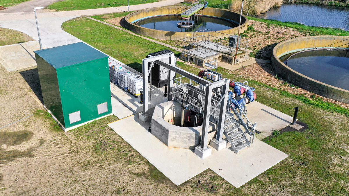
Humus pumping station – Courtesy of Southern Water
Humus rising main: The 100m long (300mm diameter) rising main from the pumping station to the converted primary settlement tanks was threaded across the site through the same narrow corridor between existing services as the 350mm diameter gravity return pipeline. The pipeline starts at the above ground pumping station manifold before channelling underground almost immediately, re-emerging around 10m from the existing tanks at the distribution chamber. The pipeline was installed at depths of up to 4.5m which successfully avoided the multiple services in the pipeline corridor.
Conversion of primary settlement tanks to humus settlement tanks: Having completed the pipeline, the next stage was to convert the PSTs to HSTs. The existing inlet pipework to the PSTs is located at the bottom of an 8m deep, narrow distribution chamber. Capping off these two pipes was undertaken via confined space access, with Rescue 2 (a specialist rescue team) on-site throughout. The tanks also needed to be isolated from the common PST outlet main. Both of these operations were completed under a site-wide shutdown and Southern Water Safe Control of Operations procedures. The tanks were now isolated from the treatment process.
The connection of the pipes from the new humus distribution chamber to the converted PSTs necessitated a large T-shaped excavation to a depth of 5m, utilising temporary works from both Coleman Construction and Groundforce. The pipe entries were made at a depth of around 4.5m, with humus effluent connections made at just below ground level.
Sludge improvements: Alongside the effluent quality driven scope, improvements to the sludge handling capacity of the site were also included in the package of works.
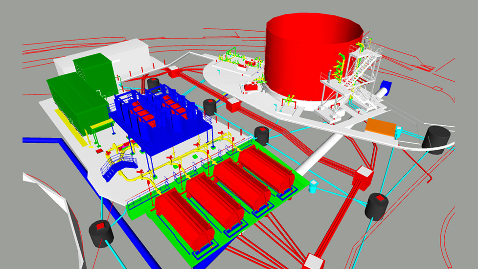
Sludge treatment area 3D CAD model – Courtesy of Southern Water
Prior to upgrade, the combined sludge flow (at between 2% and 3% dry solids content) passed to the sludge storage tanks, which were nearing the end of their usable life. The un-thickened sludge was then subjected to dewatering via a temporary centrifuge, powered by a mobile generator. The existing belt presses were not serviceable and not in operation. Sludge cake was exported from the site and process liquors returned via the works return pumping station to the screw lift pumping station for treatment.
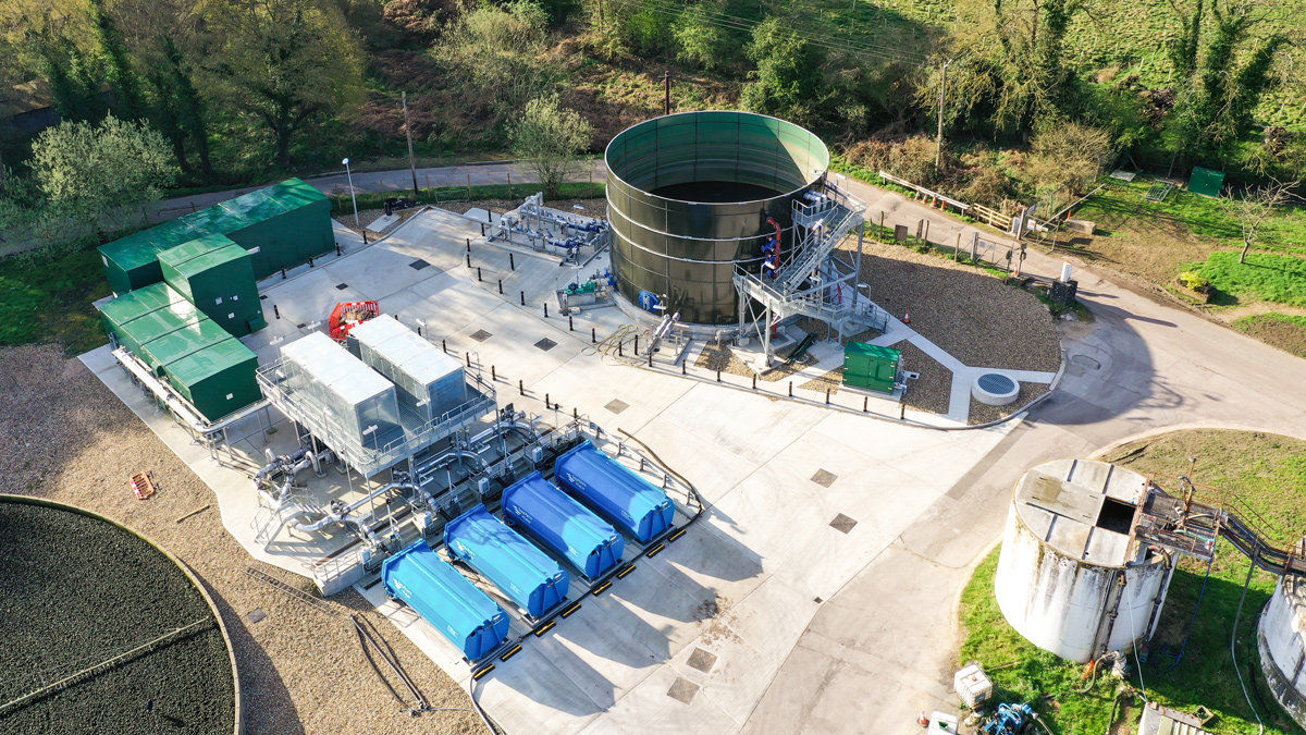
Sludge treatment area – Courtesy of Southern Water
The existing sludge storage tanks were decommissioned and replaced with a single glass-coated steel tank from Hayes GFS, which has been sized to accommodate on average 2.5 days of indigenous and imported sludge quantities.
The new sludge treatment area was built offline from the existing process. A surface drain crossing the area was to be rehabilitated under the scheme, and this was completed prior to the main work commencing. The deepest civil structure to be constructed was the sludge holding tank base. Whilst excavating, the contractor discovered waste materials which were not anticipated. Testing showed the groundwater to be locally contaminated with oil. Dewatering the excavation was going to be more complicated than first planned, so in conjunction with the Environmental Advisor the site team proposed an innovative solution. The oily water was pumped into empty intermediate bulk containers (IBCs) that were lined with a nanofilament filtration membrane impregnated with bacteria that digest oil. The IBCs were left for a week to ensure the clarified water was suitable for discharge back into the wastewater treatment process.
With work now complete, sludge is pumped from the new sludge storage tank to 2 (No.) elevated Alfa Laval centrifuges for dewatering. The elevated centrifuges were enclosed with individual acoustic enclosures, to mitigate the noise emitted during operation. The de-watered sludge (25% DS) is gravity fed via stainless steel hoppers into progressive cavity cake pumps, one for each centrifuge. The remaining centrate is fed back to the works return pumping station.
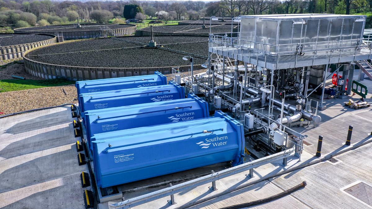
Sludge centrifuges and cake skips – Courtesy of Southern Water
To avoid excessively high pumping pressures, cake is lubricated by injected polymer which is pumped at high pressure from the Richard Alan Engineering polymer dosing unit. The cake pumps then discharge sludge cake into one of four new sealed skips which are automatically controlled by load cells and a traffic light system. Once one cake skip is filled, the process moves to the next, with the traffic light system advising which are ready for removal and which are still empty. The sealed cake skips are then transported to another site to complete the treatment process.
All the new sludge treatment assets are installed on a new area of drained hardstanding which provides a turning and loading area for the safe installation and removal of sealed cake skips.
Maintaining the tight delivery programme was a significant challenge with up to five teams totalling over 30 operators, all working in a relatively small area. The civil, mechanical and electrical work took seven months to complete and there were zero accidents or incidents.
Scaynes Hill STW: Key participants
- Principal contractor: CMDP JV
- Civils: Coleman Construction
- Mechanical & Electrical: Field Systems Design
- Shaft sinking: JG Gallagher
- MCCs: MCS Control Systems
- Chemical dosing: Lintott Control Systems
- Centrifuges: Alfa Laval
- Polymer dosing: Richard Alan Engineering
- Safety showers & eyebaths: Aqua Safety Showers International Ltd
- Sludge storage tank: Hayes GFS
- Cake skips: R&B Engineering Ltd
- Kiosk access stairs & platforms: Step on Safety Ltd
Budget and timescale
More than £1m in savings was obtained following one day of Systematic Inventive Thinking workshops and further efficiencies were achieved during detailed design including:
- Conversion of PSTs into humus storage tanks to avoid deep excavations.
- Removal from the scope of a washwater booster set.
- Removing an enlarged final effluent chamber from the scope.
The scheme successfully met the 14 November 2018 deadline for phosphorous removal, with completion of the sludge treatment area following shortly thereafter. The total cost was in line with the £8.1m pre-construction estimate.


