
Swalecliffe Short Sea Outfall (2025)
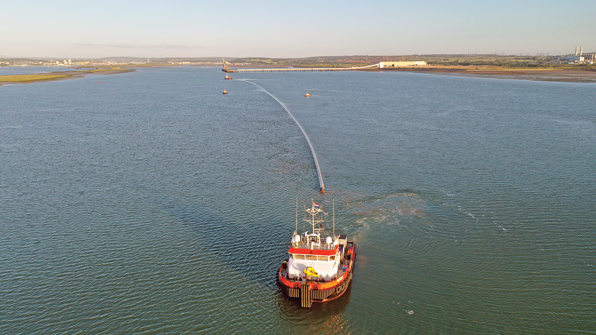
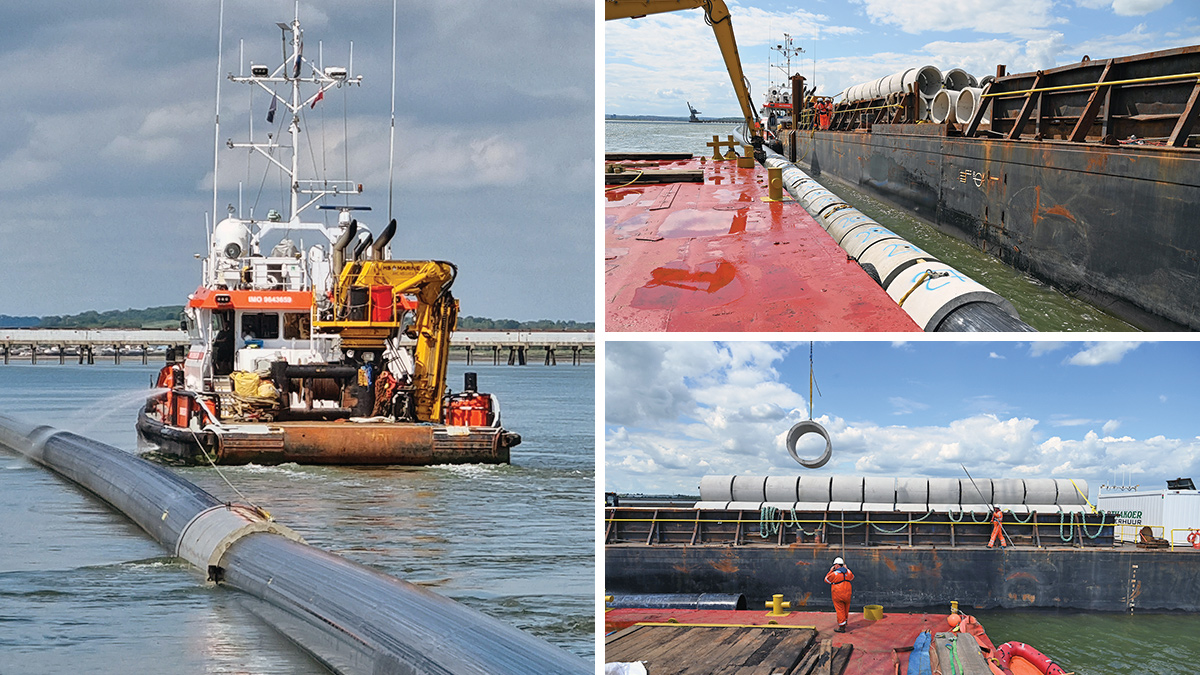
Pipe tow from Sheerness to project site for installation - Courtesy of Van Oord
Southern Water’s Swalecliffe Wastewater Treatment Works (WwTW) is located on the North Kent coast. It treats sewage arising from a population equivalent of 36,960 from the Whitstable and Swalecliffe catchments. Storm flows are discharged via both the Long Sea Outfall (LSO) and a Short Sea Outfall (SSO). The existing SSO was unable to discharge the required design flows resulting in the significant risk of on-site flooding and was also in a poor structural condition. Therefore, Southern Water undertook to replace the existing outfall with a new SSO suitable for discharging current and future flows. The paper focuses solely on the marine design and construction elements of the new 1km short sea outfall project.
Background
The existing Short Sea Outfall (SSO) is unable to discharge the required design flows resulting in significant on-site flooding and is also in a poor structural condition and therefore Southern Water proposed to replace the existing outfall with a new SSO. The existing SSO discharges flows downstream of the storm tanks within the works and following screening and retention settlement. The existing SSO pipeline traverses the existing works, behind the sea wall flood defence before progressing about 600m offshore where it discharges above the seabed in the intertidal zone.
A number of outline design proposals for the outfall replacement were developed in the early stages of the project including open cut, tunnelling and horizontal directional drill (HDD). Following optioneering, preliminary designs for the open cut and HDD techniques for further consideration, the open cut solution was selected as the preferred construction technique for the replacement SSO.
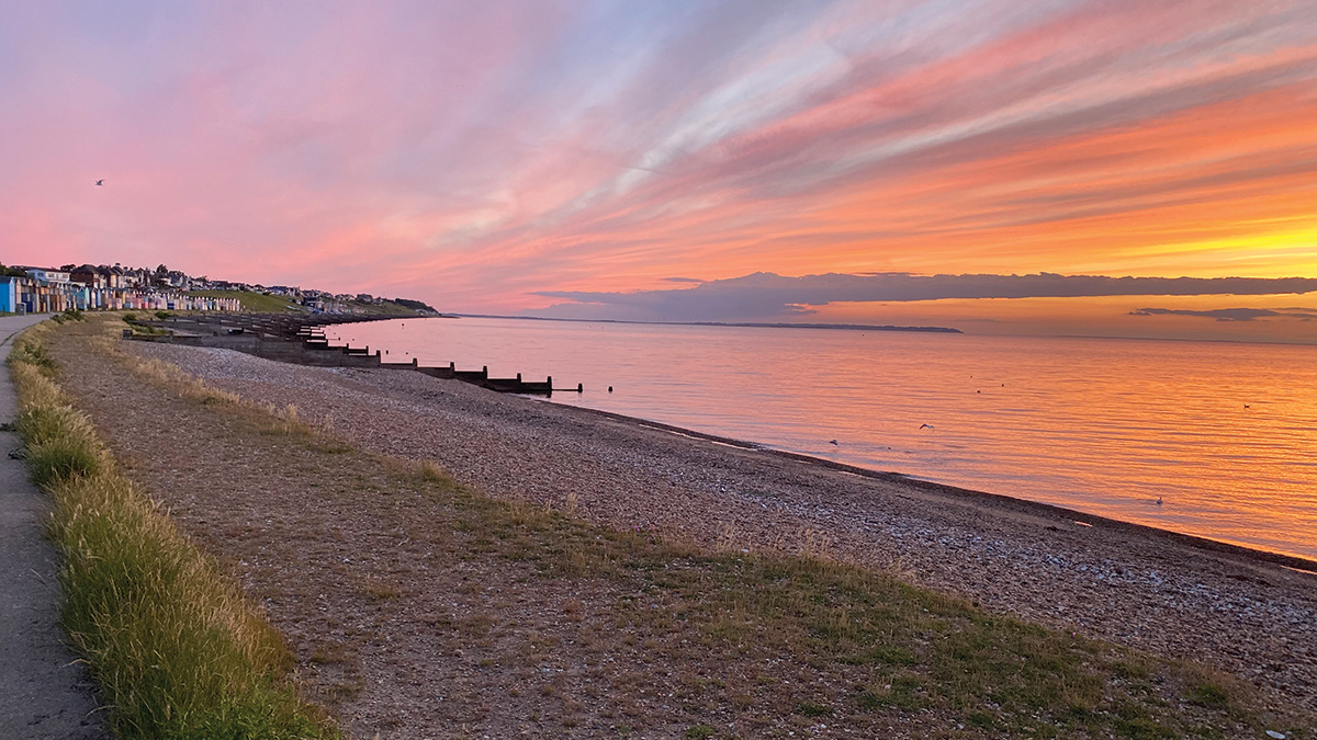
Swalecliffe beach and project location – Courtesy of Haskoning
Solution
The detailed design of the new SSO at Swalecliffe WwTW considered and finalised the new outfall pipe route, hydraulic design, preferred material and construction methodology, pipe weighting, backfill and diffuser arrangement. The outfall system comprised of a combination of 1200mm outer diameter pipeline (1200mm OD SDR 26 PE100 pipe), from a connection point onshore at the seawall and extended offshore for approximately 950m to the discharge location, and 1200mm internal diameter pipe (Aquaspira structured wall PE), from the existing storm tanks to the seawall connection.
The hydraulic design of the SSO proved to be particularly challenging as the existing works and storm tanks provided only limited hydraulic head (less than 3m total) to discharge the existing and future flows for all states of the tide. Going beyond these available heads would have resulted in submergence and potential flooding of the inlet works, screens and channel upstream. Therefore, the pipe diameters, bends and fitting losses, manholes and discharge configuration were all optimised to stay within the allowable hydraulic limits. Venting was also provided at the manholes within the land section to allow for any trapped air within the outfall due to the flow and tidal variations to be expelled sufficiently.
The outfall discharge diffuser arrangement was located in approximately 7.5m of water depth at Highest Astronomical Tide (HAT) and consisted of a single riser and single discharge port (1200mm OD SDR26 PE100 pipe) with a non-return duck bill valve from Measurit Technologies, horizontally discharging above the seabed and below Mean Low Water Spring (MLWS) tide level. The discharge location was in deeper water than the existing outfall and dispersion modelling was undertaken to indicate the predicted water quality and demonstrate regulatory compliance. Extending the SSO discharge location further offshore to achieve greater water depth was considered but was not feasible due to increased hydraulic system losses, the relatively flat nature of the seabed and the location and interaction with the LSO.
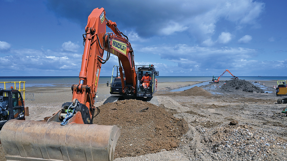
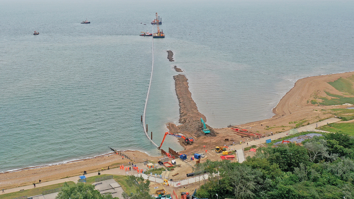
Trench excavation commences from the beach – Courtesy of Haskoning
The detailed design trench detail was developed to provide a minimum cover depth to the outfall pipeline of 1.5m following installation. This cover depth allowed for both seasonal and long-term fluctuations on the seabed levels and protection from potential damage due to dragging anchors of fishing activities. The trench was backfilled with selected as dug material, typically London clay and medium dense sands and gravels, that were side-cast during the trench excavation.
The SSO pipe was also designed to be stable in the ‘worst case’ design loads for current and wave loading conditions provided. It was therefore necessary to weight the pipeline with concrete collars to provide a specific gravity of not less than 1.35 that could be achieved without any reliance on backfill material. Due to the existing ground conditions being predominantly London clay and the potential risk of this material damaging the PE pipe during backfilling, continuous concrete collars were proposed and designed that would provide a ‘sleeve’ type protection to the pipe. These continuous collars were 1.5m in length with rubber stoppers fixed to one end to prevent damage to the adjacent collar and also provide bending flexibility during installation. The installation weight of the collars provided was 2047kg (1365kg/m) (in air) to satisfy the permanent on bottom stability.
Undertakings
The Swalecliffe Wastewater Treatment Plant Short Sea Outfall AMP7 Project was awarded to CMDP (a Costain MWH Treatment Joint Venture), with Haskoning providing detailed design, environmental and marine consenting support services and Van Oord and Davey Civils undertaking the various construction packages.
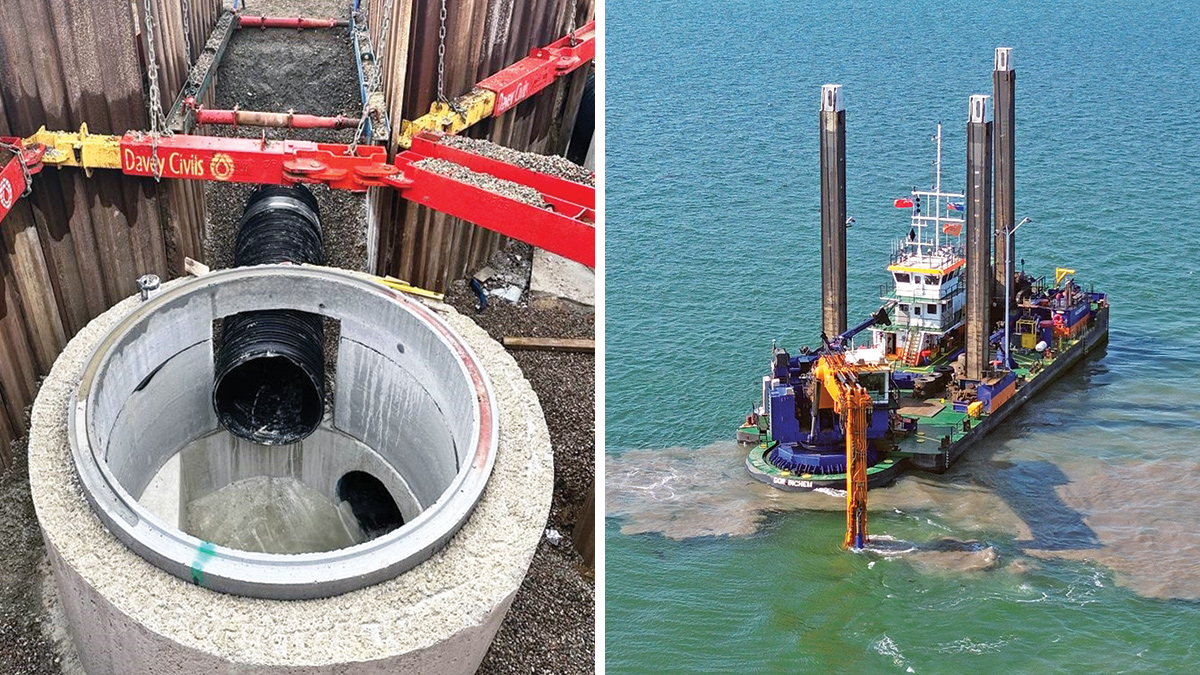
(left) Land pipeline connecting to storm tanks and (right) trench excavation offshore with Van Oord’s backhoe dredger Razende Bol – Courtesy of Van Oord
Swalecliffe Outfall: Supply chain – key participants
- Detailed design, environmental & marine consenting support services: Haskoning
- Delivery partner: CMDP
- Marine works: Van Oord
- Pipeline & land works: Mackley
- Pipeline land route: Davey Civils Ltd
- Pipe supplier: Pipelife Norge AS
- Pipe supplier: Aquaspira Ltd
- Nova Siria couplers: R2M Limited
- Concrete units: Subsea Protection Systems (SPS)
- Duck bill valves: Measurit Technologies Ltd
Site investigations
Site information was provided by Southern Water from various ground investigations undertaken prior to 2020 at the proposed site location, as well as information from the British Geological Survey’s online Geoindex borehole archive that included relevant land-based and over-water boreholes.
The soils information indicated that the site was primarily underlain by superficial Holocene deposits comprising Head, Alluvium and River Terrace Deposits, which are all laterally impersistent. On the east of the site, Alluvium deposits were indicated, while the north shoreline consisted of undifferentiated Beach and Tidal Flat deposits. On the foreshore, Beach and Tidal Deposits up to about 2m thick are underlain by the bedrock geology of London Clay Formation, and no faults were indicated.
The requirement for further site investigations were identified and these included further boreholes on land and within the works, magnetometry, sub-bottom profiling and unexploded ordinance (UXO) surveys to determine the mitigation measures required to be undertaken prior to the proposed works and construction of the pipeline. Trial holes and slip trenches were undertaken within the works to confirm service locations and an archaeological GSI was also undertaken.
Aerial view of pipe installation into trench – Courtesy of Van Oord
Land works
A length of 140m of pipe was required through the existing WwTW to connect the storm tanks to the new SSO offshore. This pipe route required navigating around existing structures, access roads, sludge tanker deliveries and over 20 buried services and pipelines. Due to the risk of saline groundwater and seawater ingress within the SSO during operation, Aquaspira structured wall PE pipe was chosen to provide the required durability. This pipe material supplied in shorter lengths with spigot and socket joints allowed flexibility during installation to work around the existing services and trench supports.
Marine works
A total length of 950m of polyethylene pipe (1200mm OD SDR 26 PE100) was manufactured by Pipelife Norge AS, in two lengths of 475m that were then towed from Norway by sea to the sheltered water adjacent to the old Kings North Power station on the River Medway for preparation and assembly.
The two pipe strings were welded together to form a single pipe length which was anchored within the river. The continuous concrete collars were fabricated off site and delivered and stored on a barge which arrived on the Medway at a similar time to the pipe. The concrete collars were lifted individually from the barge and inserted onto the end of the PE pipe and then pulled along the pipe in groups of 16 collars in total before repeating the process. During these operations the PE pipe is capped and full of air to maintain flotation. When complete, a single pipe string fitted with concrete collars was ready for towing to the project site for installation.
Excavation of the trench was carried out using land-based excavators working on low tides for the first 450m and Van Oord’s backhoe dredger Razende Bol for the marine trench. A minimum cover of 1.5m above the crown of the pipe was required for the outfall pipeline through its entire route. The excavated trench material was cast adjacent to the trench for re-use as backfill material upon completion of installation. At the sea wall crossing a short cofferdam was installed to provide trench support and maintain the existing flood protection.
Pipe flood and sinking nears completion – Courtesy of Haskoning
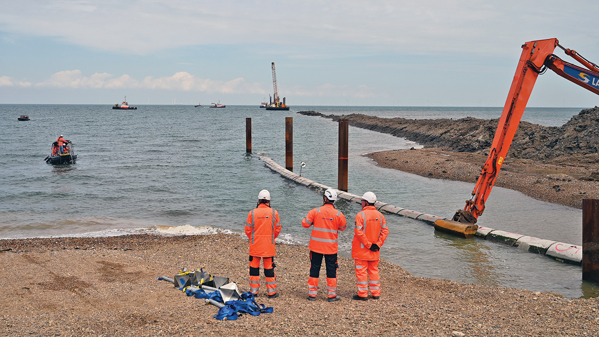
The land and marine works were managed from a site establishment within the existing Swalecliffe WwTW, which allowed direct access onto the beach and foreshore. Due to the sheltered location of the site and good beach access, Van Oord employed a self-propelled RIB survey vessel that could be mobilised from the beach at the work site. This allowed surveys of the dredging progress and pipe installation to be undertaken and processed quicker than working from an adjacent port or harbour.
Installation
With pipe preparations completed and the trench excavated, pipe installation commenced. The single pipe string was manoeuvred from the River Medway assembly site and past Sheerness Port using a combination of tugs and multi-cat. The pipe was anchored overnight just outside the working area prior to installation.
Before the sinking operation, the pipes were aligned and brought into the onshore connection point in the cofferdam using a combination of the tugs and a winch located on the sea wall. The pipes were pulled into the shore via a number of alignment piles installed as temporary works on the beach to form the long radius bend and change of alignment from offshore to onshore. The polyethylene pipelines were installed using the ‘float and flood’ method starting from the offshore end (diffuser) with air venting and pressure control onshore.
(left) Concrete ballast weights being aligned on pipe string and (right) concrete ballast weights inserted on the pipe – Courtesy of Haskoning
The sinking operation is undertaken with the controlled pumping of seawater into the offshore pipe end, initiated the sinking process which caused the pipe to form a S-curve of approximately 20m long between the seabed and seawater surface. The tugs and work boats were used in order to position the pipe correctly at the location of sinking.
As a contingency measure and to ensure the installation process was well controlled, a foam pig was pre-installed in order to create a seal between the pipe section filled with air and the section filled with water, in case the pipe had to be re-floated due to inclement weather. Once the pipe sections were completely installed in the trench, the profile was checked by a multibeam survey to verify the final pipe position. Post pipe installation, the foam pig was removed from the pipe and backfilling of the trench commenced.
Following installation of the pipe and as backfilling of the trench progressed, the diffuser riser pipe and valve were installed. To provide protection from breaking waves in the shallow location and protection from fishing and navigation risks, a concrete dome was installed around the diffuser. This diffuser was fabricated in precast concrete segments interlocking to provide the required stability during extreme conditions. The concrete segments were fabricated off-site and limited to a maximum of 50 tonnes per element for transportation and lifting from a marine barge. Rock armour protection was further provided extending around the diffuser section to protect the area from scour.
The final connection to the land section of pipe was made within the cofferdam adjacent to the seawall. The pipework was able to traverse underneath the existing flood defence which removed the need for cutting and reinstating the existing structure. The weir boxes within the storm tanks were installed allowing the SSO to be commissioned and available to discharge flows. The existing SSO outfall structure was removed offshore and decommissioned.
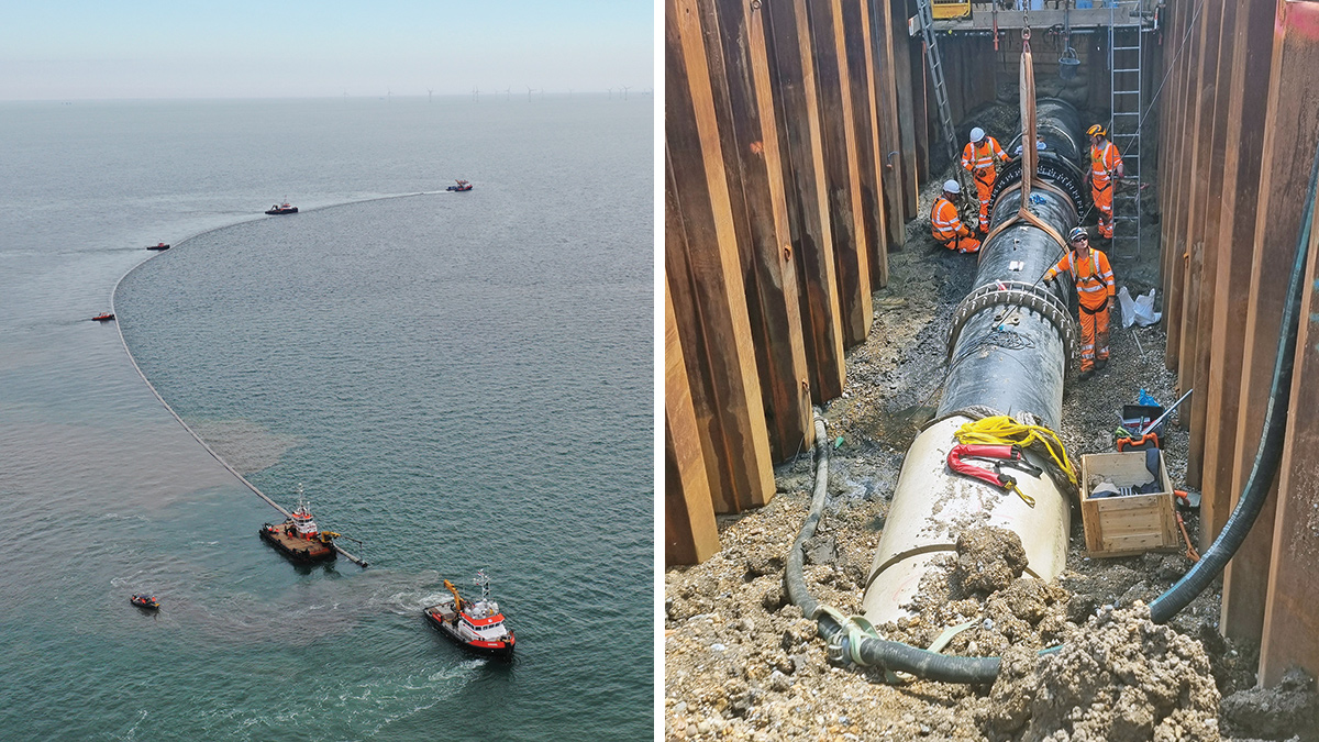
(left) Pipe tow inshore and alignment of the pipe string over the trench and (right) the completion of the connection between the land pipe and marine pipe – Courtesy of CMDP
Constraints
Swalecliffe is located to the East of Whitstable and is a popular beach and promenade, with beach huts and recreational location for the area. The interface with the public was a key part of the planning and implementation of the project to minimise any potential disruption, especially during construction.
The location of the Swalecliffe SSO is within a number of statutory protected areas for nature conservation, the Thanet Coast and Sandwich Bay Special Protection Area (SPA) and Ramsar sites, Outer Thames Estuary SPA and the Thanet Coast Site of Special Scientific Interest (SSSI), which required full consideration in the Environmental Impact Assessment Screening Requests (Kent County Council and the Marine Management Organisation) Marine Licence Application and associated Habitats Regulations Assessment and SSSI Assent.
These sites required evidenced submissions to confirm that avoiding works in the intertidal zone between October to March remained sufficient for avoiding significant adverse impacts on all features of the SPA, Ramsar site and SSSI. There were also 44 non-designated heritage assets within 500m of the site and additional archaeological investigations were undertaken for the land pipeline route.
Stakeholders
From the start of works in the public domain, the team focused on developing a positive relationship with members of the public they encountered during their work, always taking time to answer queries politely. This positive approach led to a chance meeting with an elderly local resident who returned to site with a copy of a sepia photo of his grandfather working to install a previous outfall pipe in the area, probably in the early 1900s. This prompted the site team to recreate the photo with the resident in full PPE and the story achieved coverage in the local press.
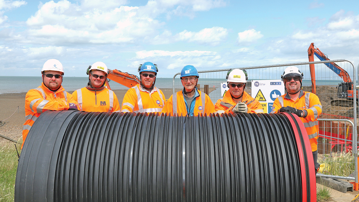
Stakeholder and local resident engagement – Courtesy of CMDP
This example of going ‘above and beyond’ was not an isolated incident – the team also providing a dog water bowl on the Esplanade, and scheduled their weekend works to avoid disrupting a local charity run, with some members of the team even staying to cheer on passing runners and offer water to those that needed it. The team also took the time to volunteer at a nearby Residential Home on two occasions, carrying out some much needed vegetation clearance. This made a tremendous contribution to not only the success of the project but also Southern Water’s wider reputation in the local area, and ultimately led to the project being delivered without a single complaint received.
Conclusions
The successful completion ahead of schedule of the design, construction and commissioning of the new Short Sea Outfall at Swalecliffe during the summer of 2024 will significantly reduce the risk of on-site flooding at Swalecliffe WwTW for both current and future flows.