
Upper Chelburn Impounding Reservoir (2018)
Mott MacDonald Bentley - MMB
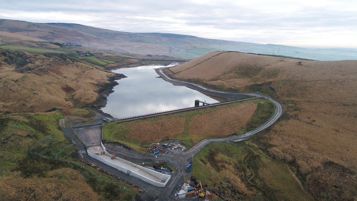
Upper Chelburn Impounding Reservoir (IR), located near Rochdale on the east Lancashire moors, is owned and operated by United Utilities (UU), providing compensation water to the nearby Rochdale canal. The reservoir is impounded by northern and southern earth-fill embankments (Figure 1), with a resulting capacity of 236,000m3. The 16.5m high northern embankment was constructed between 1799-1801, and is a homogenous embankment with a history of leakage. The southern embankment, constructed later in 1816, is approximately 3m in height, and is believed to be homogenous, with the downstream face being retained by a drystone wall. The reservoir has been constructed within a glacial valley, with significant historical post-glacial land-slips recorded along the eastern valley side. The landslips were observed to extend beneath the northern embankment right-hand abutment.
Risk reduction
The works at Upper Chelburn form part of a targeted risk reduction strategy implemented by client United Utilities (UU), termed Portfolio Risk Assessment (PRA), which when used in conjunction with their ‘toolbox’ assessment, highlights key risks to be addressed to reduce the probability of failure to an acceptable level.
Extensive ground modelling has been successfully applied to inform the design of: permeation grouting; new spillway; sheet piling and wavebund. This has added value throughout design and further, by engaging the construction team, client and subcontractors throughout the delivery of the works.
The modelling has enabled both the grouting and sheet piling solutions to be highly targeted, reducing both programme and cost, whilst also allowing for the effective design and management of temporary works to deal with a large historical landslip present on the site.
As a portion of the works required an All Reservoirs Panel Engineer (ARPE) to be satisfied as to the quality of the recorded output, constant tracking of the developing solution throughout the works has allowed for greater client, construction team and subcontractor engagement, as well as greater overall confidence in the output provided.
Upper Chelburn Impounding Reservoir: Supply chain – key participants
- Client: United Utilities
- Principal designer & contractor: Mott MacDonald Bentley
- Grouting subcontractor: Soil Engineering Geoservices Ltd
- FRC subcontractor: Offafix
Portfolio risk assessment
As part of the AMP6 Business Plan, UU made a commitment to OFWAT to ensure that its impounding reservoirs have an annual probability of failure less than the ‘intolerable’ threshold. UU uses a Portfolio Risk Assessment system, which is based on the University of New South Wales (UNSW) method. This enables ranking of the dams at a portfolio level and determines those which lie in the ‘intolerable’ zone. This is based on an assessment of seepage, stability, flooding impacts and seismic risk.
When used in conjunction with UU’s seepage ‘Toolbox’, internal erosion risks can be assessed from initiation, through continuation, to potential failure. The ‘Toolbox’ makes an assessment of the annual probability of failure modes, termed ‘Initiation Mechanisms’ (IMs). This allows remedial solutions to be targeted to provide the required risk reduction to ‘as low as reasonably practicable’.
Project scope
To address the IMs identified and the ability of the overflow structure to safely convey the PMF, the project scope comprised the following elements:
Northern embankment
- Permeation grouting of the embankment foundation stratum.
- Permeation grouting around the abandoned scour main/tunnel passing through the embankment.
- Infilling of the redundant scour main tunnel.
- Approximately 45m of new reinforced concrete spillway.
Southern embankment
- Installation of a sheet pile cut-off wall into the embankment formation.
- Installation of a wave bund to increase freeboard.
Mott MacDonald Bentley (MMB) was appointed as principal designer and contractor, and worked collaboratively with UU and the appointed ARPE to develop a solution to address the identified risks.
Upper Chelburn IR is a ‘Category A’ reservoir and is classified as a ‘Large Raised Reservoir’ under the Reservoirs Act 1975. As such, all remedial works described have been constructed under the supervision of a Qualified Civil Engineer (QCE).
Northern embankment: Ground model and embankment formation permeation grouting
A key challenge was developing a detailed understanding of the embankment construction, underlying geology and landslip zones. This ensured the solutions accurately targeted the areas requiring works without compromising the integrity of the ageing structure, providing cost-efficiencies and buy-in from the client and ARPE as the majority of the final fixes were to be below ground.
To overcome this challenge and remove need for further ground investigation, innovative new 3D geological modelling software (Seequent Leapfrog Works) was adopted to efficiently overlay and enhance the available archived ‘pre-digital’ data-sources (Figure 2). Historical data including historical bathymetric contour drawings, limited archive construction drawings and cross sections were digitised, combined with available published data (BGS geological mapping, aerial photographs and LIDAR topographical data) and site observations to construct a fully integrated interactive 3D model.
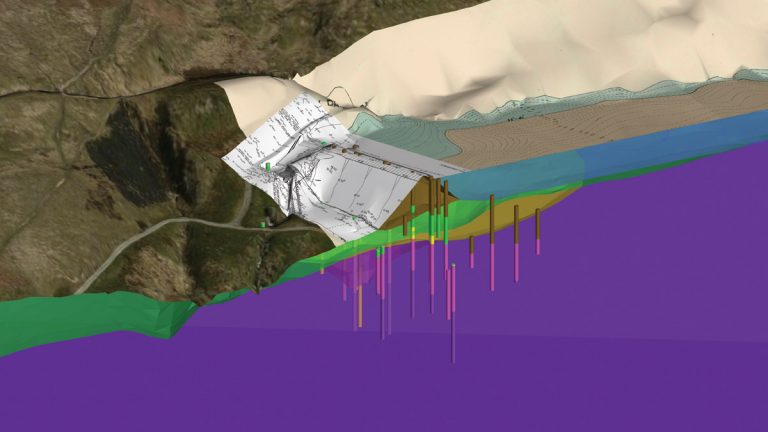
Figure 2 – The northern embankment, Leapfrog 3D ground model including historical data sources – Courtesy of MMB
This enabled targeting and detailed specification for permeation grouting works and for the southern embankment, confident specification of pile lengths. Furthermore, the 3D geological modelling was interrogated to inform efficient design of temporary excavation works to facilitate new spillway construction and foundation design. The risks associated with excavation in a historical landslip and potential uplift pressures were efficiently managed throughout design and construction.
Historical geological interpretations were relatively simplistic, iteratively approached and constrained to two dimensional outputs. Typically, this would require many iterations and sense checking to arrive at a conservative ground model. However, project Geotechnical Engineers could meaningfully and efficiently interrogate various data sources concurrently with ease. The ability to apply geological logic in three dimensions has resulted in reduced conservatism and increased efficiency in design.
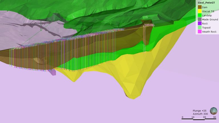
Figure 3: The northern embankment Leapfrog ground model (viewed looking downstream) – Courtesy of MMB
Increased confidence in the accuracy of the ground model reduced the amount of initial ‘proving’ works required to define limits of the grouting horizon prior to undertaking proposed works. This allowed for better definition of subcontract scope and clearer definition of the likely site works programme; all adding degrees in certainty of costs, programme and risk.
Grout horizons were determined from the ground model (Figure 3) and input into a monitoring spreadsheet indicating the position of each grout hole and the upper and lower bounds of the grouting works. The volume of grout input for each 1m lift was recorded allowing immediate visualisation and tracking of the solution progression (Figure 4). This was reviewed regularly by engineers supervising the works and aided in decision making with respect to mix design and sequencing of the grouting operation.
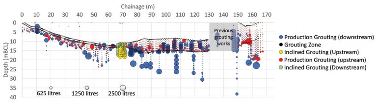
Figure 4: The northern embankment grouting works (viewed looking downstream) – Courtesy of MMB
Scour tunnel grout collar
Only a single hand drawn sketch relating to the possible location of the abandoned scour main was available from historical archives. The uncertainty of the true position of the main and extent and effectiveness of historical abandonment works (e.g. internal grouting, records were unclear as to whether the pipe was fully grouted) represented significant health and safety, and reservoir safety risks associated with a ‘strike’. To mitigate these risks, inclined grouting was undertaken from the embankment crest to install a ‘collar’ surrounding the redundant scour main tunnel (conduit) within the embankment; it was known that the former scour main had been removed from within the tunnel and as such there was no risk in striking the tunnel itself.
Due to the likely original method of constructing the scour main (i.e. in a trench along the path of the former water course prior to construction), the inclined grouting was extended vertically to meet the upper level of the main grouting works (Figure 4). In total 285,863 litres of cementitious grout (approximately 3500 tonnes) was injected through 247 boreholes (237 vertical, 10 inclined) to varying depths as specified, adopting an ascending stage technique.
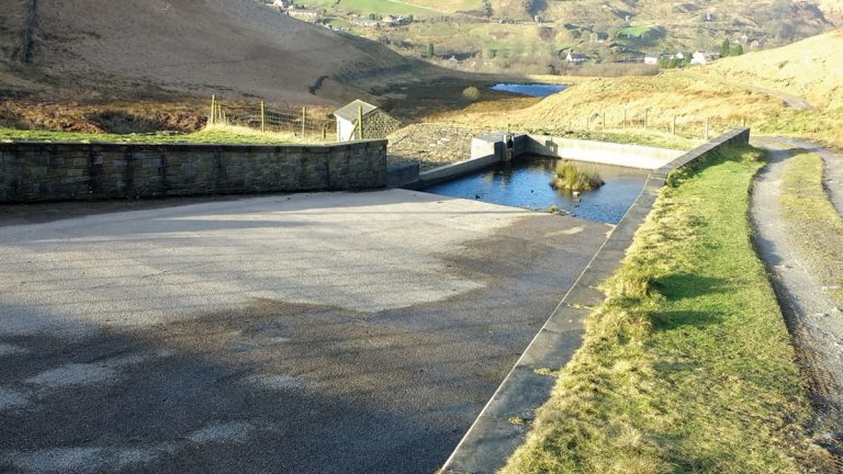
Figure 5: The existing northern embankment spillway – Courtesy of MMB
Spillway improvements
In 2011 the existing spillway (Figure 5) was overwhelmed by a storm event of unknown return period; flows over-topped a near 90° bend in the existing structure. To address the concerns surrounding the spillway, an additional 45m of new spillway was constructed (Figure 6) following physical modelling of the outline design.
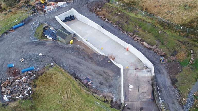
Figure 6: Northern embankment spillway (viewed looking downstream) – Courtesy of MMB
Under spill conditions (<1 in 10,000-years), flows are formally discharged via 3 (No.) 900mm ductile iron pipes with erosion managed via an apron and sandstone rip-rap (Figure 7). Flows of greater than a 1 in 10,000-year return period over-top the end-wall of the new spillway and are safely conveyed away from the embankment to the nearby clough.
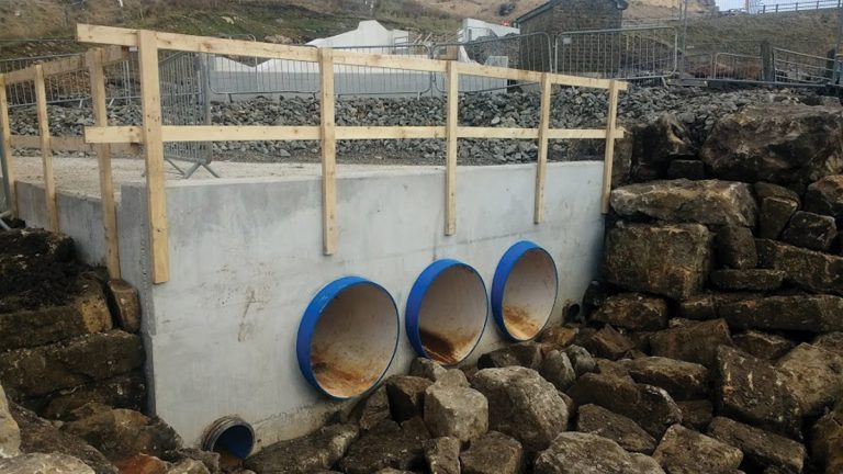
Figure 7: Spillway discharge structure during construction (viewed looking upstream) – Courtesy of MMB
The 3D ground model was used extensively for developing the temporary works required for the spillway excavation within an historical glacial landslip. Safe construction required a 5m deep battered and benched excavation with extensive temporary drainage. To efficiently design and plan the required temporary excavation works, the 3D geological model was incorporated into the project Revit 3D model. The model was further used to assess and plan the optimum crane location for spillway construction, to best limit crane size and further mitigate temporary works risks associated with plant operation in an historical landslip.
Hazards in Construction (HAZCON), and Hazards in Operation (HAZOP) meetings were undertaken internally with the design team and the client, using the Revit model for visualisation, ultimately delivering a safer design, construction phase and ongoing maintenance of the finished asset. The as-constructed levels and position of the spillway were verified using photogrammetry via drone survey.
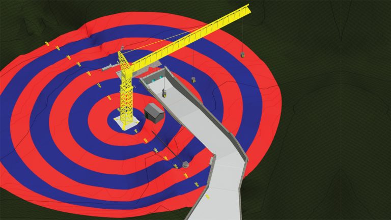
Figure 8: Overlay of crane lifting radii on the Revit model – Courtesy of MMB
Southern embankment: sheet piling and wave bund works
Initial interpretations of the ground conditions were developed within specialist geotechnical software (Bentley gINT). Outputs from these interpretations, as well as dynamic cone penetrometer results were combined within a spreadsheet allowing the project geotechnical engineer to define the interface between the glacial till/peat and thus, the required length of piles required to act as a ‘cut-off’ and satisfy the requirements of the contract.
319 (No.) GU16-N steel sheet piles of lengths varying between 3.5 to 9m were installed through the southern embankment. Initially, piles were installed using a Movax side-clamp vibrating hammer mounted upon a 38T excavator (Figure 9). To achieve final design toe-depths, an air hammer was mobilised to site.
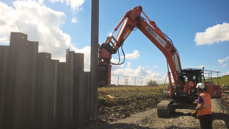
Figure 9: Installation of the GU16-N sheet-pile wall on the southern embankment – Courtesy of MMB
As downstream of the sheet pile cut-off wall the peat will become less saturated over time, consolidation settlement may be induced in the body of the dam. Therefore, the piles were embedded into the underlying glacial till to act as a cantilever retaining wall, effectively rendering the existing embankment redundant in terms of reservoir safety. Anecdotally, the interpreted ground model was verified by the point at which installation via vibratory techniques refused; indicating the level of the glacial till/mudstone bedrock interface. The resultant above-ground pile profile closely echoed the interpreted level within the design.
As part of the works to allow the reservoir to safely convey the PMF, a wave bund (Figure 10), complete with erosion protection matting was installed.
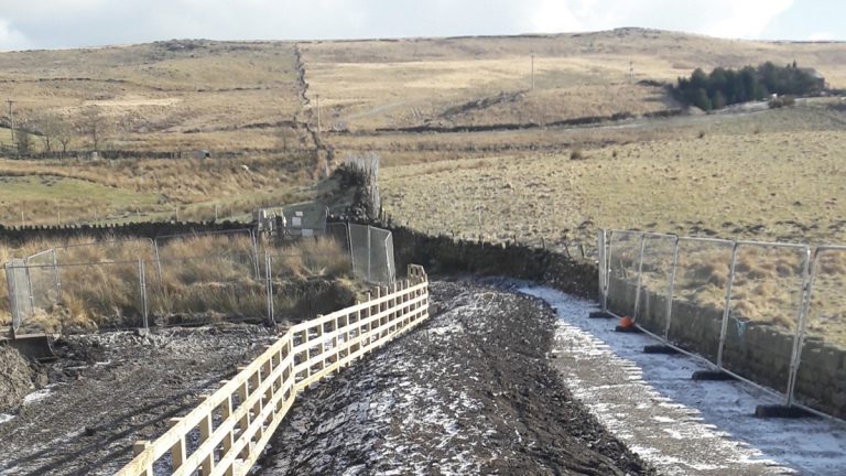
Figure 10: Southern embankment wave bund during construction – Courtesy of MMB
Conclusion
The works at Upper Chelburn IR form part of a targeted risk reduction strategy implemented by the client termed PRA. As a portion of the works requires the QCE to be satisfied as to the recorded output, the use of extensive 3D ground models and constant tracking of the developing solution throughout the works has allowed for greater client, construction team, and subcontractor engagement, as well as greater overall confidence in the output provided.
Use of extensive ground modelling on the scheme has vastly reduced the extent of initial proving works for the (northern embankment) grouting and allowed for a highly targeted (cost and programme efficient) solution for both the grouting and (southern embankment) piling works. Ultimately, the contract records have been used to achieve sign-off of the works as a whole, to satisfy a client commitment to OFWAT.
The project is within the reinstatement phase and the performance following the works will be monitored during the reservoir’s staged refilling. This article is based on a paper titled 3D geological modelling to aid efficient remedial works design and planning published in Smart Dams and Reservoirs – Proceedings of the 2018 BDS Conference, Swansea.