
Usk Reservoir (2023)
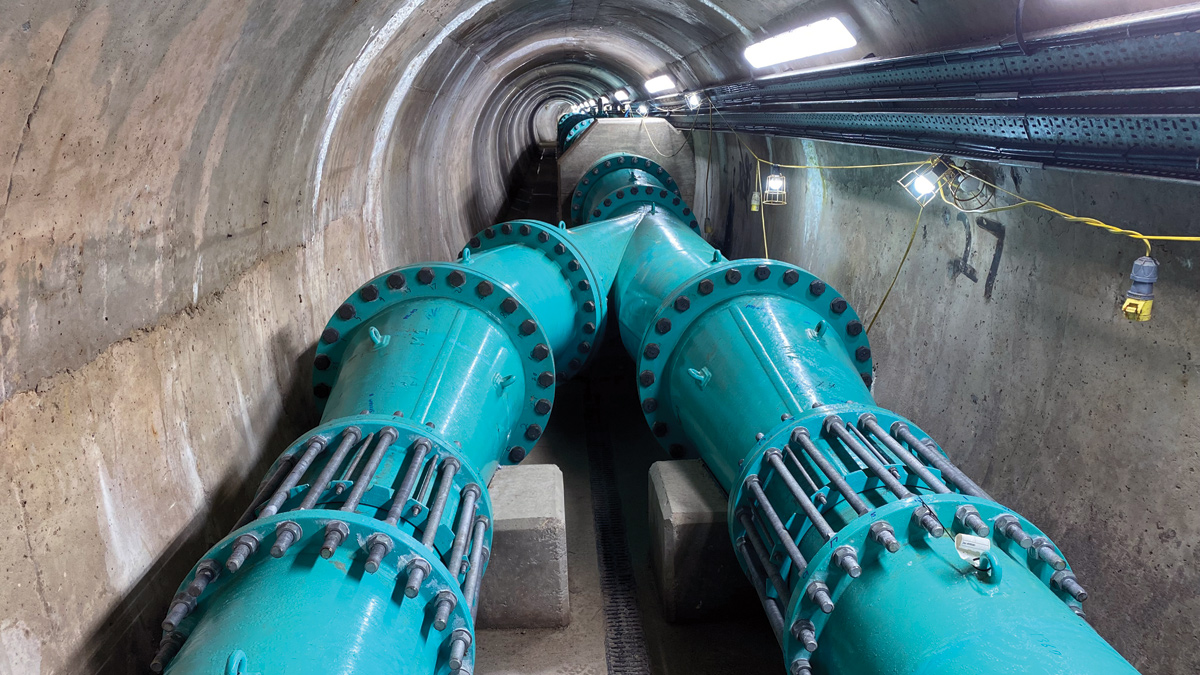
Scour pipework manifold - Courtesy of MMB
Usk is a large raised reservoir formed by an earth embankment dam, which completed constructed in 1955 with an approximate capacity of 12,268,000m3. The dam is 480m in length, with a maximum height of 31m, and supplies raw water to Bryngwyn Water Treatment Works and as well as providing compensation water to the River Usk, which is classified as a Special Area of Conservation (SAC) and a Site of Special Scientific Interest (SSSI). The project focuses on the replacement of the reservoir draw-off pipework within the dam’s outlet tunnel.
Project drivers
Welsh Water appointed Mott MacDonald Bentley (MMB), who form part of the Capital Delivery Alliance, to design and construct the replacement of both historic 18-inch scour mains in the tunnel to improve emergency drawdown capacity and to provide facility for enhanced releases to the River Usk. The works will improve drawdown capacity and as such form part of the works required to address a statutory measure in the interest of safety (MITIOS) under the ambit of the Reservoirs Act 1975.
Works to provide ‘enhanced releases’ allow a range of discharges from the reservoir, with the aim of providing benefits to the River Usk and its habitats, which is in line with the European Habitats Directive. Furthermore, the works provide enhanced releases to contribute to the United Nation’s Sustainable Development Goal (SDG) 6. In particular, it contributes to achieve the target of 6.6: ‘By 2020, the aim is to protect and restore water-related ecosystems, including mountains, forests, wetlands, rivers, aquifers and lakes’.
Optioneering
The historic pipework and tunnel characteristics caused a variety of constraints on the new system that needed to be considered when finalising the desired pipework arrangement. The project aimed to safely maximise the potential drawdown capacity whilst working within these constraints, some of which are described below.
The historic arrangement did not allow for easy inspection or maintenance. At the upstream end of the tunnel, the historic 18-inch pipes pass through a concrete plug, which cannot be replaced without a full drawdown of the reservoir. Emptying the reservoir was not feasible due to Usk Reservoir supplying large volumes of raw water for supply and compensation purposes. As a result, the historic 18-inch pipe section formed a constraint on the design and construction of the permanent works.
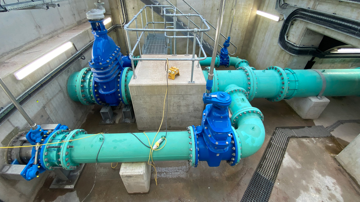
Pipework and valve arrangement within the valve chamber – Courtesy of MMB
The tunnel cross-section is a 2.4m diameter horseshoe shape. Access to the upstream end of the dry side of the tunnel is necessary to operate, inspect and maintain the new pipework and valve arrangement. The pipework arrangement and diameter needed to consider the ability to remove sections of pipework if required at a later date.
A long list of options were developed, however the chosen solution was to replace the twin 18-inch pipework with a single larger diameter pipe, offset to one side of the tunnel. This option maximised the outflow from the reservoir and maximised space for access, inspection and maintenance. To merge the two 18-inch pipe sections from the tunnel plug, an asymmetric manifold was designed to combine the flow, with guard and duty valves upstream of this. Enhanced releases are provided by two flow control valves installed offline to the new drawdown pipework, that could be remotely operated using a telemetry system located in a new control kiosk.
Other options considered during the optioneering included:
- Increase diameter of one 18-inch diameter pipe downstream of plug, with the other 18-inch diameter pipe to discharge into tunnel downstream of plug.
- Larger single pipe solutions, up to 1200mm diameter.
- Twin 600mm diameter pipes.
- Moving valve house upstream 50m to immediately upstream of a bend in the tunnel.
Design considerations
Another consideration in the pipework design, was to limit the flow velocity through the twin 18-inch sections of pipework and valves. If the system was operated for a prolonged duration with excessive velocities, there would be a risk of causing damage to the system through cavitation and excessive wear.
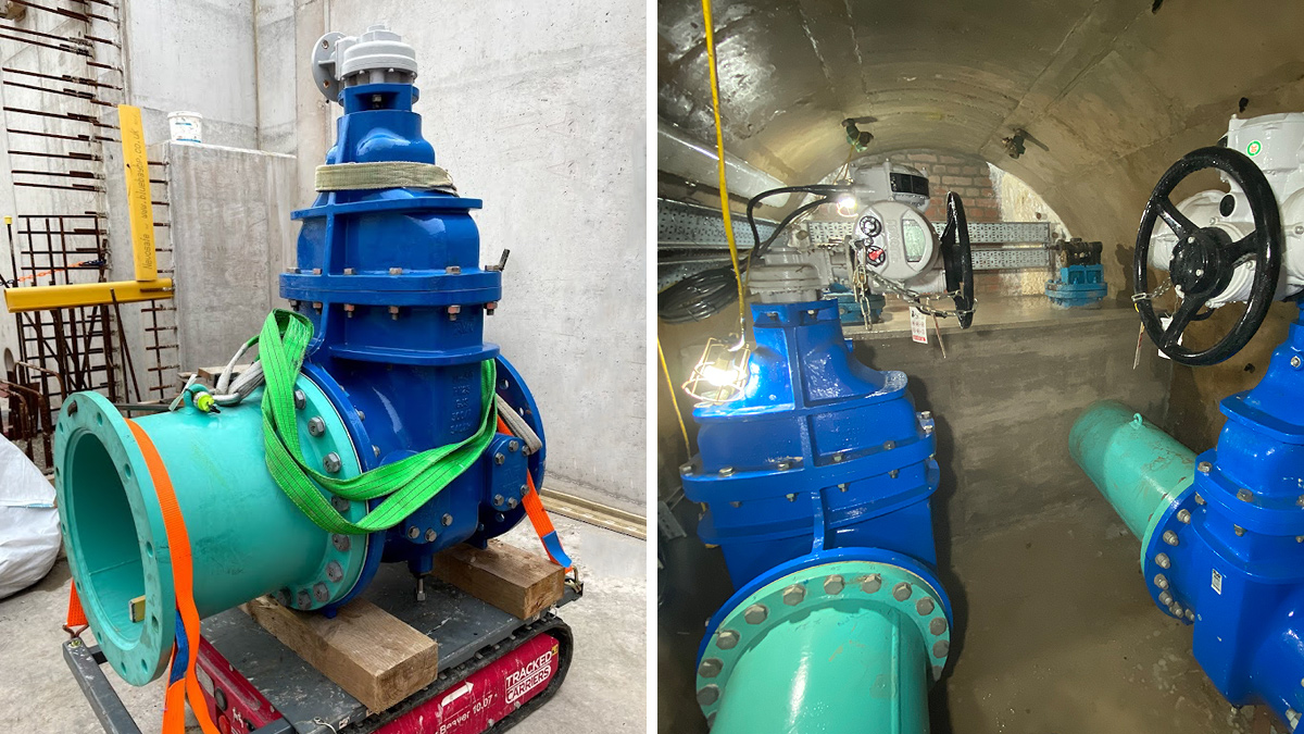
(left) Gate valve transportation and (right) bulkhead valves with concrete encapsulation – Courtesy of MMB
Following the feasibility stage, the pipework system was further optimised to improve hydraulic efficiency whilst maintaining velocities to a suitable level. The manifold was optimised to achieve balanced flows between both legs, to prevent significantly higher velocities within a single leg. The results of the optimisations enabled the diameter of the larger pipework to be reduced from the initial proposal at the feasibility stage, leading to a reduction in material costs and embodied carbon by approximate 10%.
The diameter of the larger pipework was 800mm, and the flow rate measured in the commissioning phase was approximately 5m3/s.
Concrete tunnel investigation
As some cracking had been observed to the tunnel soffit, a condition assessment of the concrete tunnel was completed. Intrusive investigations were undertaken to obtain cores to determine the cause and depth of cracking, mechanical properties, and petrographical assessment of the concrete and the section thickness. Several crack monitoring locations were monitored over a period of 21 months to determine ongoing and potential future movement. The results suggested that limited future movement will take place.
Some of the intrusive investigations also showed evidence of alkali silica reaction (ASR). Following a suite of expansion testing, the results showed that future effects of ASR would be limited and unlikely to cause significant deterioration.
To help mitigate the risk of deterioration due to water ingress into the cracks, a proactive repair to the cracks was undertaken, and long-term monitoring of the cracks was established.
Usk Reservoir: Supply chain – key participants
- Principal Designer: MMB
- Principal Contractor: MMB
- FRC works: Doohan Civil Engineering
- Electrical & control: Bridges Electrical Engineers Ltd
- Diving works: Edwards Diving Services
- Metalwork: D Hughes Welding & Fabrication
- HPPE siphon pipe: Aliaxis UK – GPS PE Pipesystems
- Pipework supplier: UTS Engineering Ltd
- Submersible pumps: Selwood
- Valves: Glenfield Invicta
- Flow controls: AFFCO Flow Control (UK) Ltd
- Flow meters: Siemens
- Concrete repairs: RAM Services
- Concrete cutting & drilling: Gnat UK Ltd
- Concrete supply: Hanson UK
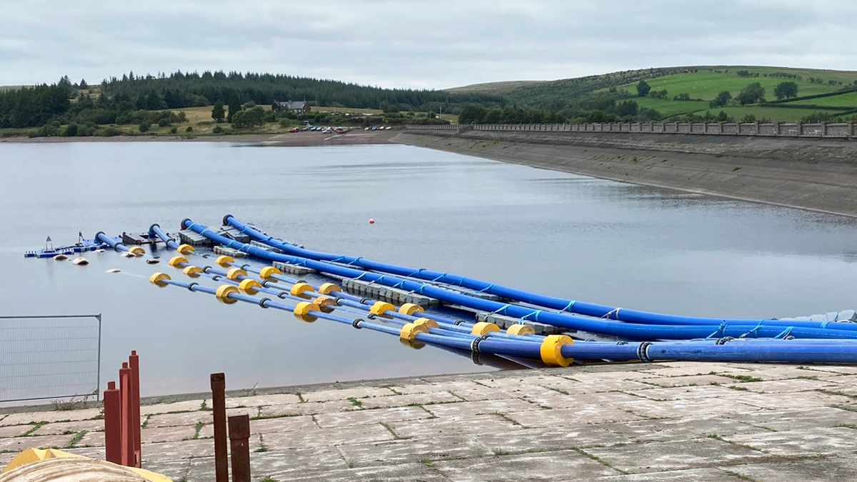
Siphon and over pumping intakes – Courtesy of MMB
Key temporary works
To maintain mandatory water compensation from the reservoir to the River Usk once the historic pipework removal had commenced, a twin siphon system was installed from the reservoir basin to the spillway’s stilling basin.
Each siphon consisted of 280m long, 400mm OD HDPE welded pipework, with ductile iron fittings. The siphon was designed to operate down to -4m below top water level, which was typical for Usk Reservoir during the summer as the water level fluctuates. It used a pump to prime the siphon, and the pump could also be used in the event the siphon loses prime to discharge the minimum compensation requirement.
The siphon was found to be reliable, and throughout the construction phase, saved approximately 260,000 litres of diesel, and 700 tonnes of CO2, when compared to over-pumping.
Construction phase and commissioning
Scope of work:
- Temporary siphon for compensation releases.
- De-commission of existing Portis supply main (including diving works).
- Demolition/re-construction of the valve house.
- Construction of new control kiosk and compound.
- Removal of three existing pipes within the tunnel, each at 180m in length.
- Installation of new electrically actuated guard and duty isolation valves, whilst working under single isolation.
- De-commissioning of the existing manual guard valves.
- Installation of the new 450mm>800mm pipework inclusive of manifold.
- Installation of valve house control valves/access metalwork.
- Security provisions.
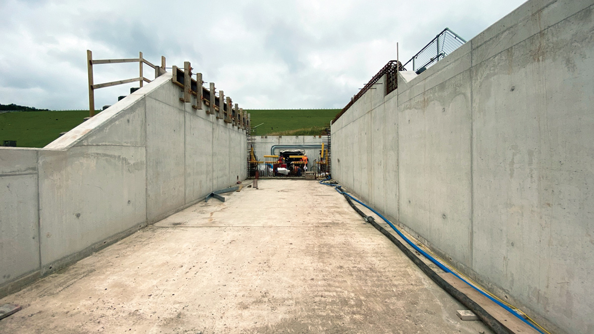
Valve chamber and tailbay – Courtesy of MMB
The historic valve house was demolished and replaced with a new buried valve chamber, and the tailbay was relined with a new reinforced concrete structure. This was due to the visual condition of the historic structures, to create a larger area for the new valve and access arrangements, and to facilitate the installation of the new pipework and valves.
The first task within the tunnel was to remove the three existing pipes. During the feasibility surveys it was found that the existing pipework and fittings contained asbestos, MMB commissioned a specialist asbestos contractor to remove the pipework adopting a pipe wrapping containment and use of a wire saw cutting technique. Once the pipework was removed all existing concrete pipe supports were also removed and the existing tunnel invert made good. Once all of the existing pipework had been removed up to the existing guard valves (at the tunnel bulk head), works to remove the existing duty valves and replace with new continued under client Gold Command control due to the single isolation nature of the works.
The works then progressed onto installing the new twin 450mm to 800mm diameter carbon steel pipework in tandem with installing a new level concrete tunnel floor. Due to the limited space within the tunnel and lack of lifting facility MMB used a small pick and carry crane which was able to transport the new pipework into the tunnel for installation. The tunnel was 180m in length with two 45° bends, this presented some construction challenges due to the limited flexibility in the flanged system.
The new valve house arrangement was then installed and incorporated the compensation, enhanced releases, and scour valves complete with extension spindle and pedestal arrangements for operation via electrical actuation on the new raised flooring arrangement.
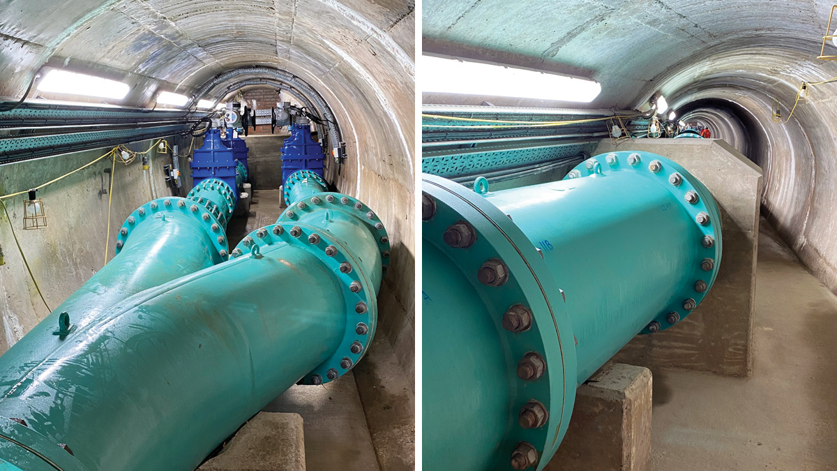
(left) Scour pipework arrangement at the bulkhead and (right) scour pipework & thrust block – Courtesy of MMB
Programme
The scheme was mobilised on site in July 2020 which presented additional unprecedented safety challenges due to the global COVID-19 pandemic. The site adopted stringent social distancing working on site and use of respiratory PPE when working in close proximity within the confines of the tunnel.
The works were undertaken under the supervision of the QCE, and the pipework and valve system were successfully wet commissioned in April 2022.