
West Hallington Reservoir (2024)
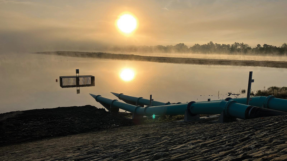
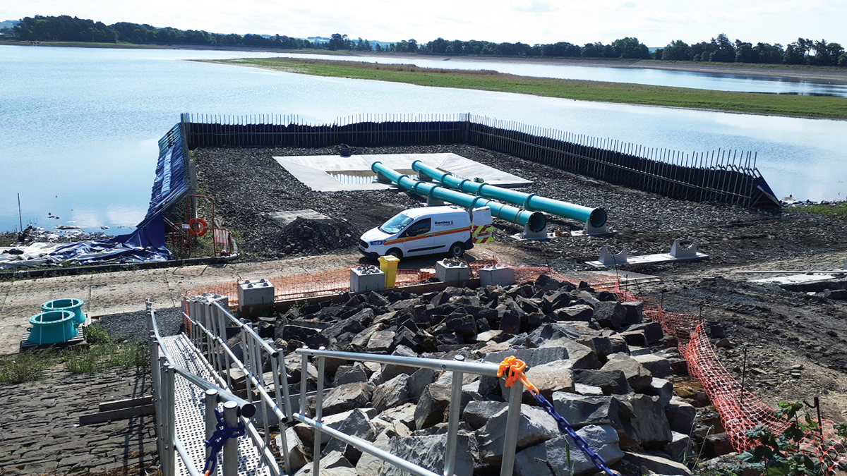
DN700 siphon pipework installed at West Hallington Reservoir - Courtesy of MMB
West Hallington Reservoir is a Northumbrian Water Group (NWG) asset situated 1km to the northeast of the village of Colwell in the Tynedale district of Northumberland. The reservoir was constructed between 1884 and 1890 for Newcastle & Gateshead Water Company for the purpose of municipal water supply. The reservoir was built adjacent to the earlier East Hallington Reservoir and operates as a non-impounding structure. It has a maximum depth of 12.1m, a capacity of 3.3Mm3 and a surface area of 50 hectares at the Full Supply Level (FSL) of 155.1m AOD.
Scope of works
An inspection carried out under Section 10 of the Reservoirs Act 1975, identified that the reservoir had insufficient drawdown capability, and thus needed to be increased such that the reservoir level can be drawn down by 4.8m in 8 days.
Mott MacDonald Bentley (MMB) developed a design solution which utilises two 700mm diameter siphons on the west embankment to operate at a combined flow rate of 3.2m3/s. The new siphon pipeline, alongside a temporary pump arrangement and the existing scour pipes, will meet the required drawdown capacity. The siphon flows will be conveyed across a stretch of adjacent field which NWG has purchased. The flows will then either percolate to ground or gravitate to the Coal Burn and eventually to the River North Tyne.
Detailed design and engineering challenges
Hydraulic analysis
MMB has designed and constructed over 25 siphons for various water companies in the UK. The siphon arrangement was analysed using an in-house design spreadsheet, and demonstrated that the siphon would break when the water level dropped 3m below top water level which was deemed acceptable.
The siphon location was moved to the west embankment due to concerns about stability and leakage through the south embankment (the original proposed location of the siphon) and because it was easier to access this area of the site.
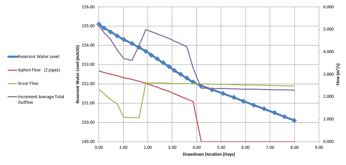
Summary chart from the reservoir drawdown hydraulic analysis – Courtesy of MMB
Pipes and thrust restraint
Hoops stresses within the DN700 mild steel siphon pipes were checked and a DWI Regulation 31 coating specified. The stainless steel pipe supports were analysed for bending and shear and concrete thrust blocks were designed for the system test pressures. The pipe wall thickness was reduced from 10mm to 8mm as an efficiency. The pipework arrangement drawing was uploaded into the federated model in BIM360 to check for clashes and when installed on site was found to fit perfectly.
Ground investigation and geotechnical analysis
Following the original construction of West Hallington Reservoir (between 1884 and 1890) the Resident Engineer Charles Henzell wrote a report to the Institution of Civil Engineers describing the works and detailing a number of challenges which included:
- Areas of soft book leaf marl overlaying harder boulder clays on the route of the embankment needed to be excavated.
- Embankments sinking or slipping and the toe of the slope reinforced with concrete walls, sheet piles and additional stepped embankments.
- Springs in the vicinity of the works.
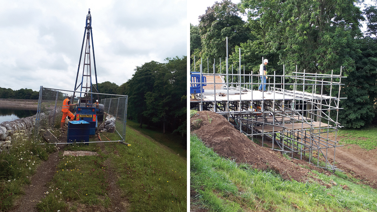
(left) Cable percussive borehole rig on the crest of the embankment and (right) scaffold decked area required for rotary bore works on the slope – Courtesy of MMB
A desk study and intrusive in situ ground investigation (cable percussive and rotary bored boreholes, standard penetration tests (SPTs), piezo installation, lab testing) were carried out to classify and determine the thickness of the superficial and solid geology along with groundwater levels, identify any contaminated or aggressive ground and determine the engineering properties of the native soils. Slope stability and ground bearing pressure checks were carried out to ensure large plant would not compromise the stability of the embankments.
The clay core and embankment material of the Pennine-type dam was found to be very silty and exhibit poor engineering qualities and so was disposed of, and a source of good quality puddle clay and Series 600-2C material was found locally at a brick factory in Birtley, Gateshead. This was installed in compliance with the test and inspection plan (T&IP) to a good standard.
Thankfully the three springs in the west embankment mentioned in the Henzell report were not encountered.
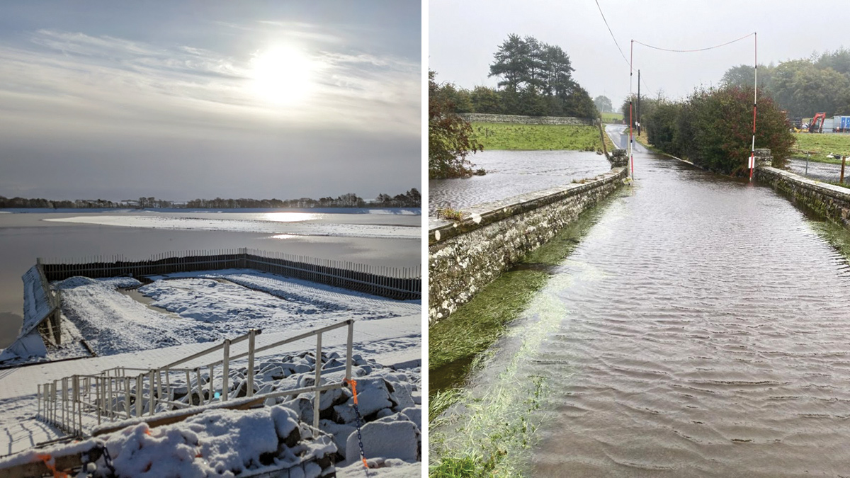
Extreme weather conditions during the construction stages: (left) winter 2022 and (right) flooding from Storm Babet (October 2023) – Courtesy of MMB
Temporary works
A borehole at the toe of the embankment on the dry side indicated the presence of water-bearing sands and gravels and so interlocking sheet piles were specified that punched through the sands and gravels into the underlying clays and so cut off groundwater flows into the excavation.
A Portadam supplied and installed by OnSite Central was employed to provide a dry area to construct the intake bay. The Portadam was erected in the wet by operatives wearing buoyancy suits, and then pumped out and an excellent seal was achieved. The Portadam also allowed plant access around the pipework whilst the stone pitching was reinstated.
Flood risk assessment
A flood risk assessment (FRA) was carried out to support the planning permission and, as due diligence, to ensure MMB would not flood a property by accident. The assessment looked at the extent of flooding during operation of the siphon along with fluvial, surface water, groundwater and finally reservoir flood risk due to an uncontrolled release (which of course the siphon is designed to help prevent). The FRA concluded that:
The maximum modelled flood extent from a drawdown of Hallington Reservoir is in agreement with the flow path identified by the Environment Agency in the long-term flood risk map and no communities are shown to be at risk due to the proposed drawdown. As periodic testing of the reservoir drawdown will occur during dry periods, it is not considered that a drawdown of West Hallington Reservoir at this location would increase flood risk elsewhere.
Synchro 4D
MMB chose SYNCHRO 4D from Bentley Systems during the latter stages of the design process. SYNCHRO 4D is software that enables MSP/P6Programme to be linked with a Revit model and to run a construction simulation.
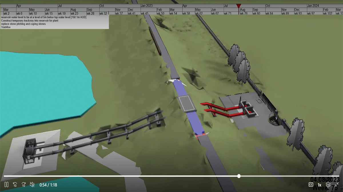
A screen dump from the SYNCHRO 4D simulation – Courtesy of MMB
The simulation highlighted a number of pinch points when materials must be delivered or when water levels must be lowered or raised and helped drive efficiencies. SYNCHRO 4D was also useful for explaining the construction process to the client, to site operatives and to visitors.
Solar power
The mechanical equipment associated with the siphon is housed within a high security kiosk. Due to the remote site location, the cost of a permanent power supply for the kiosk building services was prohibitive. A solar powered solution has been installed utilising roof mounted PV cells, DC/AC converter and battery storage.
This sustainable solution provides sufficient energy for lighting and heating within the kiosk with negligible running costs.
West Hallington Reservoir: Supply chain – key participants
- Construction delivery partners: Mott MacDonald Bentley
- Feasibility study & ARPE: Stantec UK
- Ecological surveys: OS Ecology Ltd
- Temporary water barrier (Portadam): OnSite Central Ltd
- Large diameter pipes: Powerrun Pipe-Mech Ltd
- Electrical/instrumentation installation: Intelect (UK) Ltd
- Large diameter valves: AVK UK Ltd
- Large diameter valves: Glenfield Invicta
- Valve actuators: Varley Hydraulics Ltd
- Stonemasons: Stuart Marley Ltd
- Steelwork fabrication: AJ Engineering & Construction Services Ltd
- Steel fixing: D&N Reinforcements Ltd
- Kiosks: Technocover Ltd
- Bespoke steel access cover: EJ
- Solar panels: Green Leaf Engineering

Solar panel display – Courtesy of MMB
Construction: Problems, successes and lessons learned?
Intake bay
The intake bay was located along the Small Burn which originally ran across the middle of the reservoir and was diverted into the adjacent Coal Burn in the 1880s via a DN375 clay gravity drain. The ground around the intake bay was found to be poor and was excavated down to competent sub-grade and reinstated with 340 tonnes of gabion stone and 60 tonnes of Type 1 capping material. As this area is normally under a 5m depth of water it was inaccessible during the ground investigation stage.
Pressure testing
As the DN700 pipes are fabricated from coated mild steel, a Type 1 pressure test (water loss method) was required. All bolts had been tightened using Hytorc© equipment and the torque readings recorded in the T&IP, but achieving a pass proved difficult due to sunny weather. A temperature rise on the above -ground pipework led to a pressure loss of more than 0.2 bar in the water filled pipe voiding the test on a number of occasions. Eventually cloud cover enabled a valid test; one of the only times a site team has prayed for the sun to go in!
Siphon intake bay constructed within a Portadam barrier supplied and installed by OnSite Central – Courtesy of MMB
Stone pitching
Reinstatement of the original stone pitching (to resist wave action) took seven weeks longer than planned; mainly down to availability of stone masons. Productivity increased as the works progressed and the three man gang went from replacing 3 to 5m2 per day. The stone pitching was reinstated to a good standard, but it was felt that the detailing around one of the pipe supports would be built differently next time.
The 2,500m perimeter of the reservoir had been faced with stone pitching down to original ground level; installation of which in the 1880s without an excavator and selector grab must have been a job and a half!
Ecology
Prior to the construction works, NWG employed OS Ecology to undertake trapping for white clawed crayfish, a native species that is in decline due to the introduced North American signal crayfish. No white clawed crayfish were found within West Hallington Reservoir but three were trapped within the adjacent East Hallington Reservoir. A pied wagtail nest was spotted by eagle-eyed site workers next to the engine of an excavator. The excavator was withdrawn from service until the eggs had hatched and the fledglings left the nest.
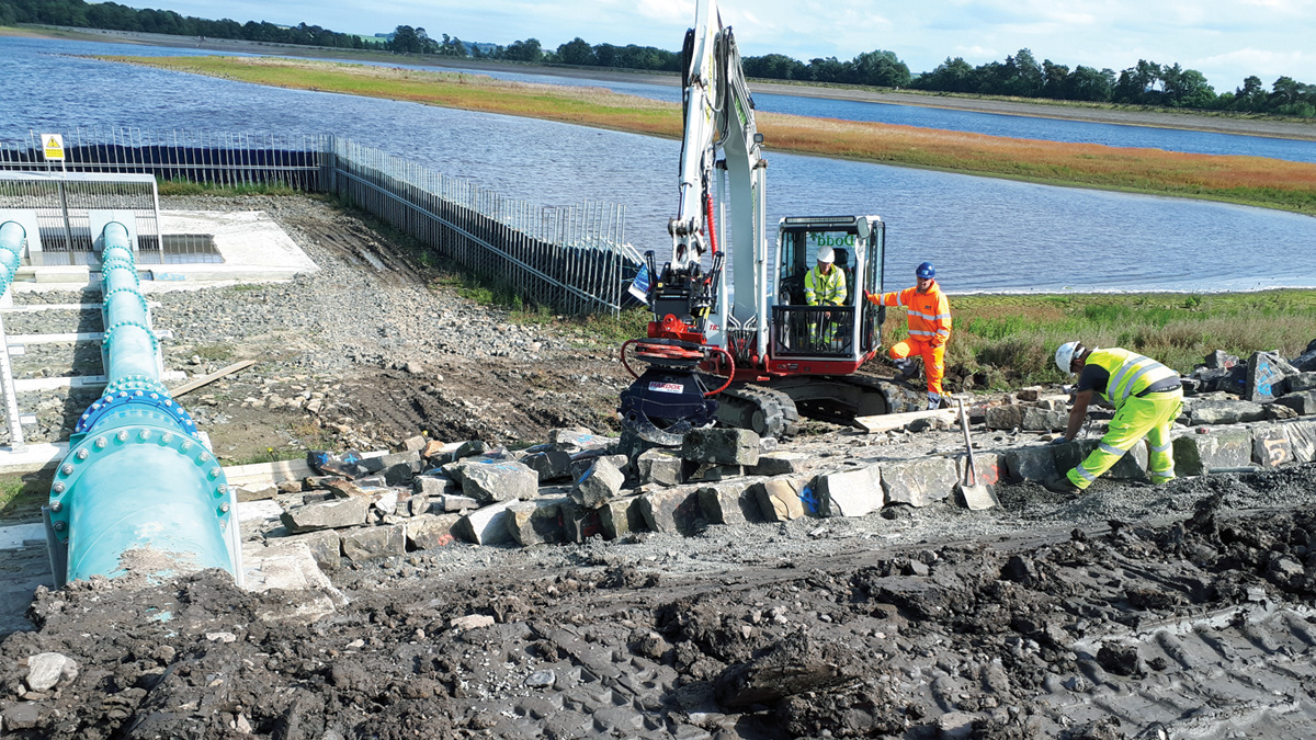
Reinstatement of the stone pitching – Courtesy of MMB
Testing, commissioning & conclusions
The siphon is designed to operate above a water level of 152.5m AOD and to self prime above a level of 154.1m AOD (TWL = 155.1m AOD) and so the All Reservoirs Panel Engineer (ARPE) requested that during the testing and commissioning stage, MMB should demonstrate the following:
- That the siphon can be primed between the water levels 152.5m AOD and 154.1m AOD.
- That the siphon can self-prime above a water level of 154.1m AOD.
- That the Full Supply Level of 155.1m AOD can be achieved.
The water level rate was restricted to 300mm/week and any seepage through the clay core will be monitored in future via a flow measurement chamber.
During operation of the siphon, receiving watercourses and culverts were monitored at a number of locations to ensure scour or carriageway flooding were recorded and the test halted if required.
The works were completed within budget (final NEC3 contract value £3.3m, £60k gain pot) and on time. The original compliance date of 31 September 2023 was extended to incorporate obtaining the Section 166 agreement and a new date of 30 June 2024 was agreed with the ARPE.
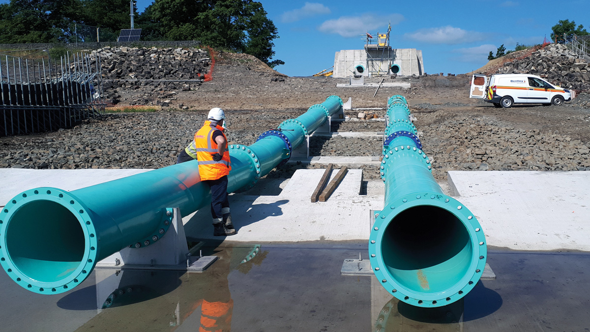
DN700 siphon pipework during installation – Courtesy of MMB
Leaving a legacy
Northumbrian Water is very keen on creating community projects and “leaving a legacy”. MMB widened the access from the main road and provided three passing places as the access route is used by both residents and members of the fishing club.
Looking ahead
Northumbrian Water are investigating another 10 reservoir sites that potentially require siphons, and so Mott MacDonald Bentley hope to use the good practice and experience learned at West Hallington Reservoir on other schemes in the future.
A Northumbrian Water Engineering Briefing Note for siphon design and construction is also underway, which captures all the learning and good practise and will sit alongside the newly published CIRIA 813 Siphons in Dams: Design, Installation, Operation, Management and Testing.
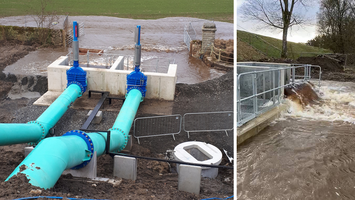
Siphons operating (January 2024) - Courtesy of MMB
