
Ambergate Strategic Service Reservoir Renewal: Phase 2 (2017)
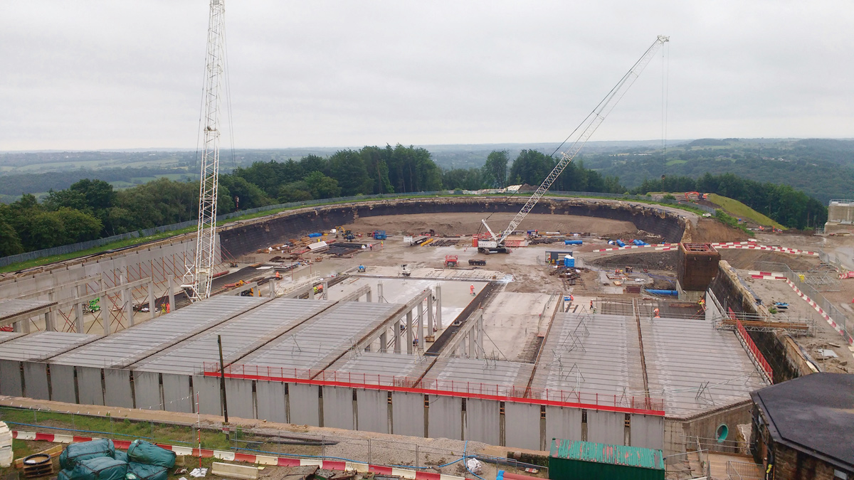
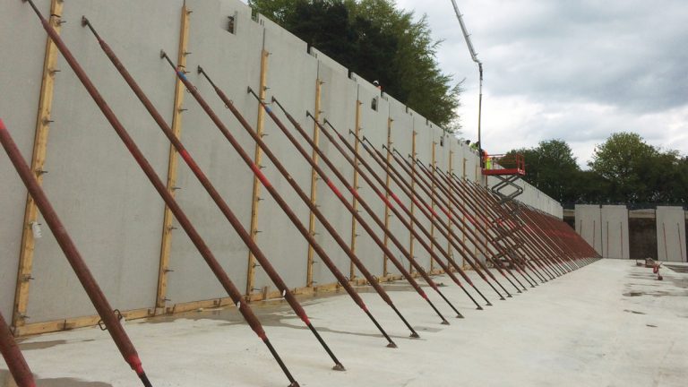
Ambergate Reservoir Phase 2 under construction - Courtesy of Laing O’Rourke/NMCNomenca
The existing Ambergate Reservoir was commissioned in 1907 and formed a part of the Derwent Valley Aqueduct receiving water from the Upper Derwent Valley. Water treated at Bamford WTW is delivered to Ambergate Reservoir by gravity via the aqueduct. The existing reservoir had a capacity of 128Ml supplying water to the cities of Derby, Nottingham and Leicester and the surrounding areas. The reservoir was identified as in need of replacement in 2008 after statutory inspections of the structure had indicated that its condition had deteriorated. The inspection highlighted significant cracking in external walls, the roof slab condition was deteriorating, and ancillary structures were in poor condition. Difficulty in operating, cleaning, inspecting and maintaining the reservoir were reasons for opting for a complete replacement rather than refurbishment.
Background
The existing site is sited in a rural location surrounded by ancient woodland. The client was keen to minimise disruption to this environment and considered a number of options. The selected option was to divide the project into two phases. Phase 1 was to construct a new 87Ml two-cell reservoir adjacent to the existing – this first phase is described in UK Water Projects 2015.
Following commissioning of Phase 1 the additional required storage capacity is to be provided by demolition of the existing reservoir and the construction of a 50Ml third cell on the footprint of the existing as part of Phase 2.
Site constraints
Due to the planning constraints on the number of HGV movements into and out of the site, the decision was taken to retain excavated material on the site despite the difficult topography and shortage of space. A reinforced earth system was used to allow 80,000m3 of material excavated for the new reservoir to be stockpiled on site. The long term proposal for any material not utilised in the backfilling of the new reservoirs will be to place it within the remaining half of the redundant reservoir. This will be suitably landscaped to create a substantial surface water attenuation area to regulate runoff from the site. Working with the project ecologist and Derbyshire Wildlife Trust, this area will be reinstated as a wet meadow, further diversifying the proposed range of habitats on the site and helping to support local populations of the nationally scarce Dingy Skipper butterfly.
To further reduce HGV movements, the team also utilised precast solutions and installed a temporary concrete batching plant on site.
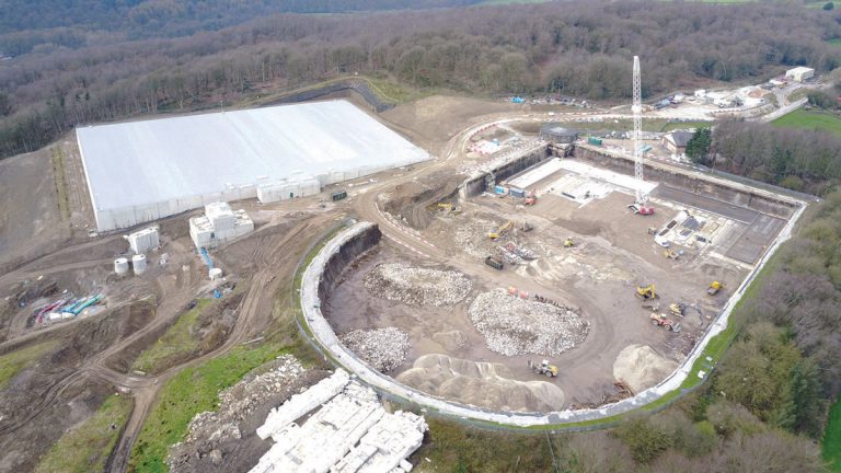
Aerial photographs showing completed Phase 1 and Phase 2 under construction – Courtesy of Laing O’Rourke/NMCNomenca
Procurement
Laing O’Rourke operates modern large precasting facilities near Worksop and in Swadlincote, which supplied precast concrete structural elements for the reservoir roof for Phase 1 using a process of Design for Manufacture and Assembly (DfMA). The supply of factory produced elements for assembly on site had the effect of reducing the programme with a consequent health and safety advantage by reducing site hours. The use of DfMA has been fully embraced on Phase 2 of the project to include wall construction using an innovative ‘twin-wall’ system.
Atkins Global was employed by the partnership as designers for the project, continuing a strong relationship that had already been formed with both Laing O’Rourke and NMC Nomenca (now Galliford Try) from previous Severn Trent projects. The team, split between their Warrington and Belfast offices, has extensive experience of the water industry with the necessary hydraulic, structural and geotechnical skills.
Design of Reservoir 2
The design of Reservoir 1 described in UK Water Project 2015 details how the first two cells were constructed utilising in situ concrete for the base and walls and adopted a DfMA solution for the columns and roof.
The design of Reservoir 2 is an excellent example of what can be achieved through detailed early coordination between the designers, Atkins, the site team and the factory. Similar to the first two cells of Reservoir 1, the columns and roof comprise of precast elements with a DfMA solution adopted for the perimeter walls.
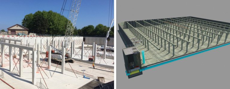
(left) Precast elements being installed and (right) extract from BIM model showing Phase 2 – Courtesy of Laing O’Rourke/NMCNomenca
The precast twin-wall system comprises two skins of reinforced concrete the height of the reservoir and a typical width of 3m. The overall wall section is 400mm thick. The precast wall sections are lowered on to the vertical reinforcement springing from the in situ concrete base and the void between is filled with in situ concrete forming a monolithic structure. Great attention to detail is required to ensure that the reinforcement does not clash with the panels as they are landed. Excellent coordination in this respect has avoided the need to amend any of the panels as they are landed. The tops of the wall panels have been detailed to allow for the erection of the precast beams which along with the roof construction tie the tops of the walls forming a composite structure.
To achieve the volume required for Reservoir 2, the walls needed to be 8.1m tall making it one of the tallest full height twin-wall water retaining structures constructed by Laing O’Rourke to date. To reduce soil pressures on the walls an innovative solution was adopted. Approximately 2,400m3 of polystyrene was recovered from the roof of the previously demolished reservoir. This will be used to part-backfill the reservoir walls and negated the need to dispose of the material off site resulting in an extremely efficient design solution and reducing the carbon footprint of the scheme.
The BIM model was used to optimise the sequence of erection of the wall panels and close coordination between the site team and the manufacturing facility producing the wall units ensured that the panels could be cast in the most efficient order to minimise any need for panel storage at the factory or on site.
DfMA
Early in the design process for Phase 2, a comprehensive workshop was held to review best practices and lessons learnt from previous projects that had used similar DfMA elements. From this review, key elements such as column and beam connections were standardised.
To allow standardisation of twin-wall panels, an exercise was carried out to understand the optimum size, taking into account the number of in situ concrete stitches, the weight of deliveries to site and cranage limitations. The output from this review was to alter the shape of the reservoir to allow the best panel layout to be used.
The construction programme for the reservoir was also re-sequenced to best suit the production and delivery rates for the DfMA elements.
Value engineering
Modelling in the early stages of the project confirmed the optimum size of the reservoir as 137Ml and with planned future development upstream at the Bamford WTW and improvements to the Derwent Valley Aqueduct the reservoir was required to accommodate a throughput of 200Ml/day. By examining various options it was found that by limiting the flows into the cells at top water level to 170Ml/day and using the bypass at these conditions it was possible to reduce the feed pipework diameters significantly from 1,400mm to 1,000mm resulting in savings in pipe materials, valves, flow meters, and associated valve/meter chambers.

Nivus wetted ultra-sonic flow meter – Courtesy of Laing O’Rourke/NMCNomenca
Incorporating new technology to the outlet flow meters made significant additional savings. Due to the critical importance of the reservoir, (both existing and proposed), the project required all construction and operation to be carried out without interruption to flows. The original design called for full bore ‘Magflo’ meters, which would have required bypasses to be installed in the pipework to allow for maintenance/replacement. Research by the client revealed that the use of ‘Nivus’ wetted ultrasonic flow measuring technology would provide high accuracy flow measurement whilst negating the requirement for the bypasses, by facilitating the replacement of electronic components without the need for shut downs.
Collaboration between the client, design and construction teams, utilising 3D visualisations, helped to realise the potential benefits, which resulted in significant savings by virtue of simplification of the pipework design and elimination of bypasses and valves which, in turn, generated reduction in the size of the civil structures.
Connections at the existing inlet and outlet mains were carried out whilst the main was live to avoid loss of supply to customers using under-pressure tapping techniques. Further isolations to redundant mains have been completed using a similar technique with under-pressure line stops.
Building information modelling (BIM)
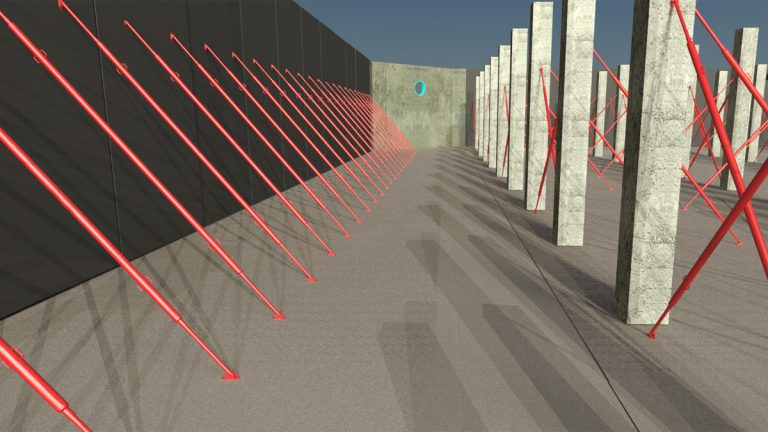
Temporary works shown in BIM model – Courtesy of Laing O’Rourke/NMCNomenca
From inception, there was constructive dialogue between all stakeholders to consider expectations for the project, particularly with regard to the client’s performance requirements. Regular design and development reviews, involving the whole project team, using digital engineering and the 3D model were instigated. The digital model produced during the design stage was instrumental in achieving agreement on details of operability and maintenance with the client. This has led to cost savings through minimising late changes during hand-over.
The design and construction teams have further initiatives planned for Phase 2 to enhance the DfMA process, including modelling of temporary works supporting precast elements and linking the risk register to the model via risk beacons. When navigating around the model, risks will be highlighted and information given.
Temporary works installed on site – Courtesy of Laing O’Rourke/NMCNomenca
Component tracking
The digital model has been developed to allow the live tracking of all precast structural components. From the beginning stages of the design intent, all the way through to the installation, the status of a particular element could be identified through the model. The ability to track the progress of each component gave the site team the confidence that all the units would be available for delivery when required. This helped to prevent delays during the construction of the reservoir.
When the site team was ready for a certain component to be delivered to site, it was called off directly from the model; greatly assisting in communication between the relevant parties. The components were then loaded onto a lorry, which was tracked via GPS by the project logistic manager on a programme called Road Runner. This programme allowed all deliveries to site to be booked into specified delivery slots allowing the cranes on site to be utilised in an efficient manner.
All these tools help minimise the amount of potential disruption to the local community and has also helped reduce the overall construction period of the project.
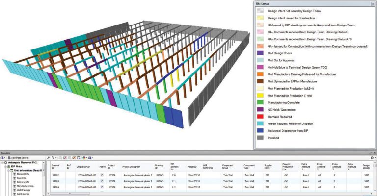
Extract from component tracking database – Courtesy of Laing O’Rourke/NMCNomenca
Community engagement
Due to the rural location of the site, there was some opposition to the project within the local community. A full project Environmental Impact Assessment was undertaken along with extensive customer consultation. Planning permission was granted in 2012 with a number of conditions. A traffic management plan limited the number of HGV movements during the day and also restricted permitted times that vehicles could use the local road network to avoid coinciding with local schools opening and closing times.
Engagement with the community has continued throughout the construction phase. A community liaison group chaired by the leader of the local council, and including representatives from County, Borough and Parish Councils, as well as local residents was established. Regular meetings were held on site with the project team who encouraged the group to raise any concerns they had as well as giving project progress updates.
At early stages of the project, residents initially had some concerns about potential disruption but as the project progressed trust was developed and these concerns were allayed. Trust was engendered through open and transparent engagement, including open days to site with invitations extended to local residents and presentations delivered by the project team to local community groups.
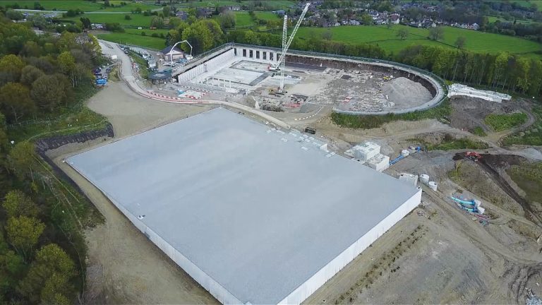
Aerial photographs showing completed Phase 1 and Phase 2 under construction – Courtesy of Laing O’Rourke/NMCNomenca
Conclusion
Phase 1 of the project was commissioned in December 2016 and has now been handed over to the client. The existing asset has been decommissioned and construction of Phase 2 is underway, due for completion in Spring 2018.