
Ayrshire Resilience: Phase 1 (2016)
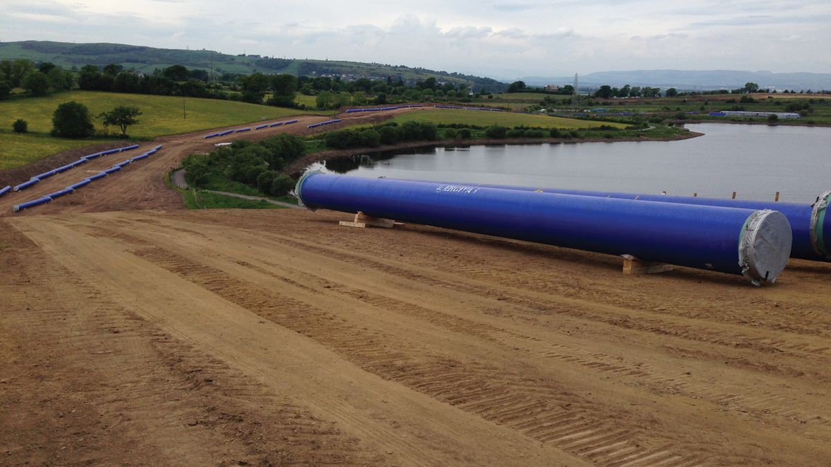
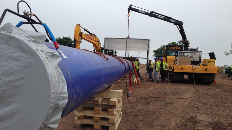
Pipe laydown - Courtesy of Caledonia Water Alliance
Scottish Water has recently commenced the first phase of construction on a £120m investment project designed to improve the drinking water network throughout much of Ayrshire and parts of East Renfrewshire. The project involves the installation of a new large diameter strategic water main from Newton Mearns continuing down towards the Fenwick/Waterside area and finally terminating at a water treatment works (WTW) close to Dundonald. Once complete, this project will benefit more than 200,000 of Scottish Water’s customers both residential and commercial. Caledonia Water Alliance (CWA), working in partnership with Scottish Water, developed the initial design concept ready to progress to the construction phase and is now ardently working on the installation of welded steel pipe sections.
Pipeline design
CWA design development involved intense option investigation and analysis. With pressures in the pipeline projected to exceed 20bar at points, the design team identified steel as the most suitable option for the pipeline material. The preferred optimal pipeline design was determined to be welded steel pipes coated with 3 layers of medium density polyethylene (MDPE) and lined with an epoxy resin.
The key element to this steel pipeline option is the novel jointing system adopted, whereby the E-Joint is an insulated joint which makes it possible to weld the pipe sections together without causing any damage to the internal epoxy resin lining. The design team considered the next best alternative, a butt fusion welded system; however it was designed out to avoid the need for man entry to the pipeline, to repair any damage to the internal lining caused by the welding process.
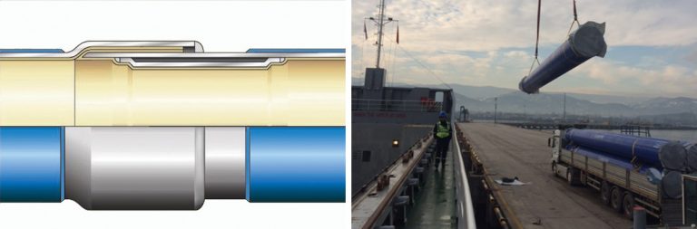
(left) Typical E-Joint and (right) loading pipes off the ship – Courtesy of Caledonia Water Alliance
Corrosion can be an issue with steel. To alleviate concerns and protect the pipe, the pipeline design incorporates three separate elements to form a complete protection system:
- Step 1: Apply an epoxy lining internally.
- Step 2: Apply a 3-layer MDPE coating externally.
- Step 3: Apply an impressed current cathodic protection system.
This strategic water main project comprises a pumping station, a service reservoir which acts as a break pressure tank and 3 (No.) steel pipelines (1 (No.) rising main and 2 (No.) gravity mains).
Water will be pumped from south Glasgow approximately 14km to a new service reservoir, and from there, will feed Amlaird Water Supply Zone (WSZ) by gravity. A steel pipeline, approximately 3.3km long, will be laid in parallel with the rising main from the new service reservoir to feed South Moorhouse WSZ, where a 1.6km HDPE branch will be laid and also incorporate a blanked off branch, which will later be connected to a main feeding Eaglesham. A 3.7km branch from the gravity main feeding Amlaird WSZ will connect to Corsehouse WSZ via a smaller 355mm diameter HDPE pipe.
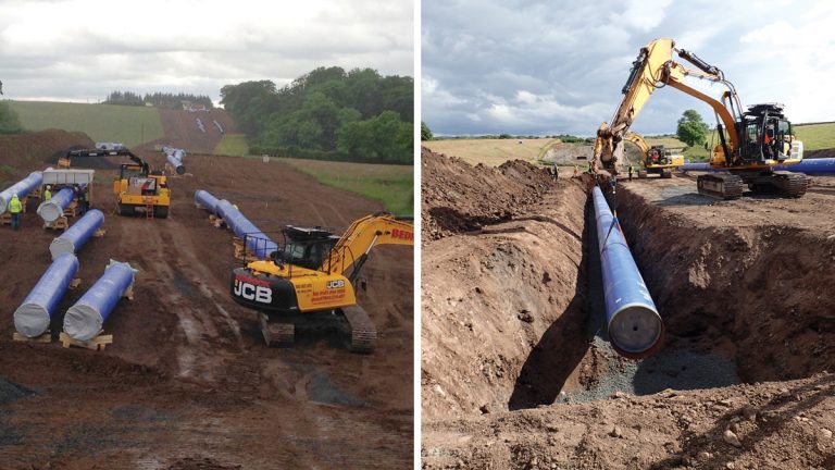
(left) Excavation prior to pipe laying and (right) pipelaying in progress – Courtesy of Caledonia Water Alliance
On a £120m investment project such as this during an unsettled economic period, CWA is overcoming a variety of challenges in order to support Scottish Water to achieve optimum service and value for money, with all required fittings, chambers, iron work, plant, backfill materials, concrete etc. supplied via Scottish Water’s own dedicated supply chain. CWA, in partnership with Scottish Water, has successfully formed close working relationships with a number of key suppliers which has included a broad range of companies, specialist suppliers and consultants.
Scottish Water’s supply chain has assisted in getting various subcontractors, suppliers of plant and equipment, and other specialists such as archaeologists, geotechnical/mining/tunnelling experts, and environmental consultants on board.
For the Amlaird Strategic Water Main Project, CWA and Scottish Water have worked with AE Yates Trenchless Solutions and JBA Consulting for provision of tunnelling expertise, ESG for carrying out the ground investigation works, FT Pipeline Systems Ltd for supplying the steel pipe and AVK for supplying the valves.
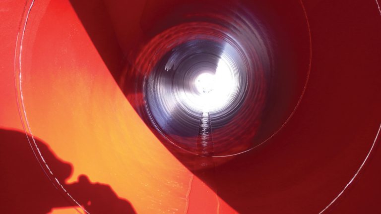
Internal view of pipe – Epoxy resin lining – Courtesy of Caledonia Water Alliance
Engineering constraints & challenges
To support efficiency in design and construction phases, the project was split up into four manageable sections, each with their own constraints and challenges which had to be addressed. During initial design development stage, a suite of environmental screening was conducted and highlighted the following items which critically affected the pipeline design and route planning.
Section 1: 900mmø steel rising main
KEY PURPOSE: Connect Glasgow water network to new service reservoir to feed Amlaird WSZ and to facilitate water transfer between Greater Glasgow and Ayrshire.
Ground conditions: Old mine and quarry workings: Historical mine and quarry workings were identified within the Dams to Darnley Nature Reserve. In the case of mining, historical records indicate the location of known shaft entrances but do not show the associated shaft tunnel locations or depths.
Specialist environmental advisors conducted a desktop study followed by physically walking the planned pipeline route to identify any mine workings which could affect the planned route. Discussions with CWA design team evolved to settle on agreed alterations to the pipeline route which would avoid known shaft entrances thus reducing associated risk level for construction works.
Ground conditions: Deep peat: Areas of deep peat greater than 3m in depth posed issues for the pipeline design as the peat was determined to be in a near liquid state and as such too soft to support any excavation or pipe installation activities. Construction through peat poses issues with either floating or sinking.
A 900mm diameter steel pipeline could potentially float when first installed and require to be held down in position. Conversely, once the pipe is commissioned and running at full capacity, the weight of the water could potentially force the pipe to sink. Welded joints on a steel pipeline are not expected to be flexible and if the pipe was to sink into exceptionally soft ground conditions, then the risk of a joint failure cannot be ruled out.
The final design incorporated excavation to competent ground and consequently, building up with imported fill material. The pipe was also held down using specially designed ‘saddle bags’ at regular intervals to counteract the float effect. The works were completed utilising an integrated peat management plan to manage the careful handling, storage and reinstatement of the fluid peat layer.
High voltage power lines: At various points along the planned pipeline route, construction works have had to be adjusted to suit working in close proximity to high voltage 132Kv and 275Kv power lines.
Crossing or running parallel to these power lines has required direct consultation with the energy provider and tailoring construction works to comply with their set working guidelines, with regards agreed working height restrictions or stand-off distances.
Gas pipelines: The planned pipeline route crosses a number of steel high pressure gas pipelines, each with their own individual cathodic protection systems. Preparations for such crossings has required direct consultation with SGN and National Grid, tailoring construction works to comply with working guidelines, agreed stand-off distances and depth of cover. The water pipeline passes beneath these gas pipelines, crossing at 90o and between identified welded joints.
Contaminated land: Two areas of contaminated land were identified in the vicinity of the planned pipeline route. Without the potential to mitigate out the risk of contamination, the pipeline route was altered to avoid the areas.
Railway crossing: The preferred pipeline route meant that it would be necessary to cross beneath a section of a live railway line. Consultation with Network Rail determined that the pipeline design would need to incorporate twin reinforced concrete tunnels to mitigate risks associated with ground vibration which may disturb normal rail operations and also to minimise the associated risk should a burst occur at the point of the railway crossing.
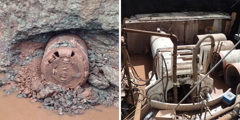
(left) Rail tunnel reception pit and (right) Rail tunnel drive pit – Courtesy of AE Yates Trenchless Solutions
Collaboration with FT Pipeline Systems’ own fabrication shop was essential in the development of special bends and support system for the tunnel pipework. The initial tunnel depth estimations ended in rock; hence the design steered towards a large reduced level dig as opposed to sinking caissons.
Motorway crossing: Similar to the railway crossing, it was agreed with Transport Scotland that where the preferred pipeline route would cross the M77 motorway, the pipeline would be laid in twin reinforced concrete tunnels.
The 1,500mm diameter twin tunnels crossing beneath the M77 required a large reduced level excavation for the reception pit. This was deemed to be more appropriate than sinking caissons in solid basalt underlying the motorway at this point.
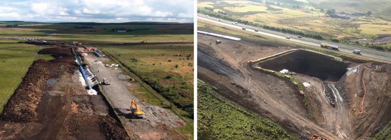
(left) Ariel photo of pipe route and (right) M77 Motorway Crossing TBM reception pit – Courtesy of Caledonia Water Alliance
Section 2: 1,000mmø steel gravity main
KEY PURPOSE: Connect new service reservoir to Amlaird WSZ to facilitate water transfer within Ayrshire.
The new service reservoir is to double as a break pressure tank. It is the hub for 3 (No.) pipelines, which can each be configured to act as inlets or outlets, and as such required the design of a complicated valve arrangement. As with Section 1, this section of the pipeline is also affected by the majority of same constraints. Planning conditions also necessitated a full habitat survey and an environmental watching brief to be undertaken.
Section 3: 900mmø steel gravity main plus 400mmø HDPE branch
KEY PURPOSE: Connect new service reservoir to South Moorhouse WSZ to facilitate water transfer within Ayrshire and parts of East Renfrewshire.
The principal engineering constraint is crossing 2 (No.) high pressure steel gas pipelines, twice.
Section 4: 355mmø HDPE branch
KEY PURPOSE: Connect new service reservoir to Corsehouse WSZ to facilitate water transfer in Ayrshire.
Major Road Crossings: The principal engineering constraint with this section is the crossing by directional drilling of the M77 and A77 for the 355mm diameter HDPE branch, as opposed to the tunnelling option employed for the main M77 crossing. The M77 and A77 directional drill for the 355mm diameter Corsehouse branch is still in the design and approval phase; drilling operations within this section will encounter peat and basalt.
Project benefits: Customers & the environment
The project has developed from the solution to a water quality issue for a single works into one which will now main out 3 (No.) ageing WTWs and provide a resilience link thus improving efficiency of Scottish Water network assets. The project will improve network resilience by forming a direct link between the Greater Glasgow and Ayrshire communities, enabling transfer of water from Glasgow to Ayrshire, and vice-versa, if required.
The strategic water main is designed to operate in both directions, where the typical operational regime will be pumping water from south Glasgow to serve the new service reservoir in Ayrshire, with the mained out WTWs fed by gravity from the tank. The Reverse Resilience Mode is for water to be pumped from Ayrshire via a pumping main to be constructed in the next phase, via the Amlaird pipeline to the service reservoir and gravitating to south Glasgow, South Moorhouse and Eaglesham.
Weld inspection – Courtesy of Caledonia Water Alliance
The project will contribute to a more robust and connected supply zone, benefiting Scottish Water’s customers across Newton Mearns, Eaglesham and a number of key towns and villages across parts of Ayrshire. The new resilient and expanded network will enable Scottish Water to establish a sustainable solution to raw water quality issues (pre-treatment), to provide greater security of supply across this section of the network, respond more effectively to operational issues thus minimising disruption and reduce long-term costs to their customers.
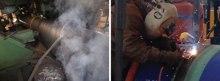
(left) Steel pipe fabrication – Courtesy of pipe manufacturer Erciyas and (right) welding in action – Courtesy of Caledonia Water Alliance
Progress to date
CWA has been working hard over the past 18 months in order to deliver a fit for purpose design and progress into the construction phase of the project. CWA consulted with potential large subcontractors, however in May 2016, the decision was taken to self-deliver effectively giving the delivery vehicle full control of the project, providing a saving for Scottish Water on the cost of an extra layer of overheads.
The final route deviated slightly from the original proposal for several reasons, predominantly linked to land issues and ground conditions such as avoidance of a designated SSSI, evidence of historic mine workings and, where possible, avoidance of very deep peat up to 8m in depth.
The construction phase began picking up pace from February 2016 with the start of Right of Way fencing and land drain diversions. May 2016 had seen a rapid mobilisation of CWA resources, plant and equipment, to the extent that by the end of the month, most of the topsoil stripping for the route was complete.
Ground investigations and route proving started back in September 2015, involving a specialist ground investigation contractor to undertake trial hole and borehole investigates. Ground investigation data was essential for the design of the tunnelled sections beneath the railway and motorway crossings. Consultations with Network Rail and Transport Scotland progressed well and work on the tunnels, with excavation work for the tunnel entry and exit pits commencing at the end of June 2016.
The first tunnel drive under the railway line was completed in early August 2016. Pipe-laying also started in early June 2016.
To date, the project is on target to meet Scottish Water’s key target for the WSZ by achieving our anticipated completion date and the regulator’s water into supply date set for the end of March 2017.