
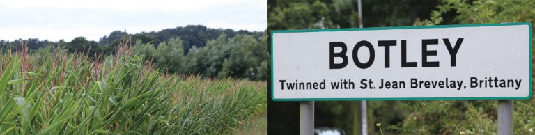
Botley Park Trunk Sewer (2016)
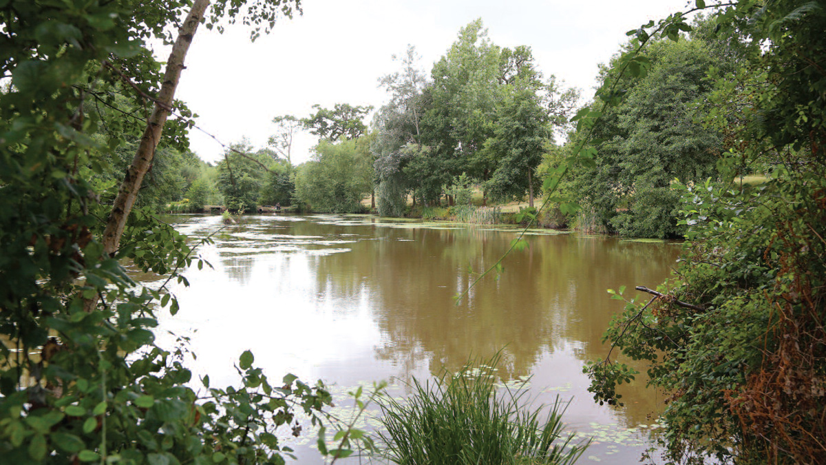
Botley Park pond - Courtesy of Mott MacDonald
The Ashill Group is building a development of 1,400 new homes and businesses to the east of Southampton on Botley Park Golf Course and the adjacent farmland. As the local sewerage undertaker, it is Southern Water’s statutory duty to connect this development to its foul sewer network. Following initial investigations, Southern Water confirmed that the proposed development would significantly increase flows to the public sewerage system which may put existing properties and land to a greater risk of flooding. In response to these investigations, Ashill Group requisitioned a new foul sewer under Section 98 of the Water Resources Act (1991). This represents an investment of over £8m in sewerage infrastructure.
Introduction
Southern Water commissioned Mott MacDonald to undertake options appraisal, statutory Environmental Impact Assessment, Town & Country planning application and detailed design under the Master Framework Agreement (MFA) for AMP5 (extended into AMP6).
A new pumping station and new trunk sewer will be constructed to collect wastewater from the new homes and businesses and transfer flows to the existing Brook Lane Wastewater Pumping Station (WwPS) to the south east of Botley. From here wastewater is being pumped to the Peel Common WwTW in Fareham where it undergoes final treatment.
Outline design: Route selection
A number of potential route options were considered with a direct route initially chosen largely along roads between the new development and Brook Lane WwPS. This route included works through the Botley High Street Air Quality Management Area and following consultation with Eastleigh Borough Council the air quality effects were deemed too significant for this option to go ahead.
The final route alignment is approximately 5km long and avoids Botley High Street. It runs mainly through open countryside on privately owned farmland and on this land a traditional open-cut pipe laying technique is planned. There are three main roads and a railway line which have to be crossed. At these locations trenchless techniques are proposed such as horizontal directional drilling (HDD) to minimise disruption and reduce risk associated with buried services.
The new pumping station will be constructed within what is currently the golf course to pump flows in a rising main along the first 2.5km of the route. Once flows reach the high point, they will travel the remainder of the route under gravity. Most of the gravity sewer follows the alignment of an existing gravity foul sewer up to Brook Lane WwPS.
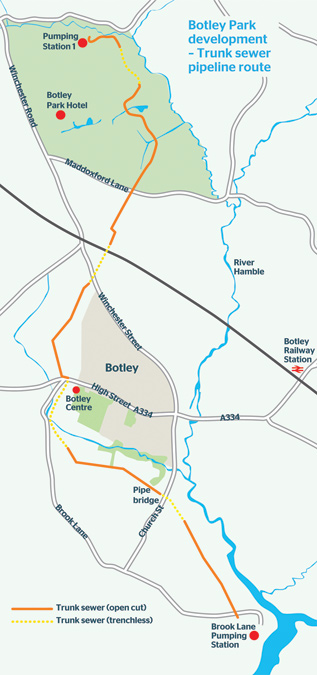
Botley Park Development trunk sewer pipeline route – Courtesy of Mott MacDonald
Non-dig construction via HDD and the associated inverted siphons are planned at two locations in order to reduce disruption and minimise construction risks. The pumps and the motor control centre (MCC) at Brook Lane WwPS will be upgraded to cope with the additional flows.
The pipe diameter will vary between 315mm and 400mm. The trunk sewer has been designed for a peak flow of 67 l/s. A 315 OD SDR17 PE main has been selected, which gives a velocity of 1.15m/s at peak flow. The gravity pipe section will be a 400 ID structured wall plastic pipe in the open cut sections and 315 or 355 OD SDR11 PE in the HDD sections. The gravity section of the trunk sewer will generally be laid at very low gradient, because it is restricted by existing ground levels and the invert level at discharge.
Surveys and ground investigations
Manholes and culverts along the route were surveyed by Dene-Tech Services Ltd to provide information where there were crossings with the proposed sewer or where the new sewer will follow the alignment of the existing sewer. The data from the manhole survey was also incorporated in the hydraulic model.
A ground investigation to obtain geotechnical and environmental information was carried out along the route of the proposed new sewer including the on-site pumping station. It was completed by Environmental Scientifics Group Ltd. Cable percussion boreholes and machine-dug trial pits including sampling, in situ testing and laboratory testing were undertaken. Hand excavated inspection pits including CAT scanning were undertaken to determine the position and depth of existing services along the pipeline route.
Additional ground penetrating radar survey was undertaken to determine the depth and location of services that were not found using inspection pits and CAT scans.
The ground levels along the proposed route were determined using data from a topographical survey undertaken by 3D Engineering Surveys Ltd. The topographical survey was completed using a combination of unmanned aerial survey vehicle, terrestrial LiDAR method and conventional topographic surveying method. A digital terrain model was created from this data; this was used in the pipeline design. A topographical survey of the development site was provided for use in the detailed design.
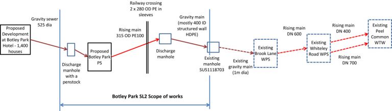
Botley Park SL2 scope of works – Courtesy of Southern Water/Mott MacDonald
Design elements: Botley Park WPS
The new pumping station will receive foul drainage from the proposed new development. The pumping station design flow is 67l/s. The inlet manhole will incorporate an isolating penstock. There will be two pumps, fitted with variable speed drives. At the initial development phase the WPS will operate at 45l/s. There will be a valve chamber, housing non-return valves, isolating valves, a Bauer coupling and an air valve. A flow meter in a separate chamber will also be provided.
The site will be provided with a chemical dosing plant for dosing Nutriox into the flow in order to prevent septicity occurring in the rising main. The pumping station compound will be fenced out and will be provided with a concrete hardstanding.
Design elements: Railway crossing
The railway crossing will be constructed via auger boring. A twin crossing is required, proposed as two 280 OD PE carrier pipes in a 600mm OD steel sleeve. Only one leg will be operational at a time. Parallel to the railway, there is an existing 42” high pressure gas main. Due to the 3m clearance required from the gas main, the crossing will be approximately 8m deep and therefore the valve chambers at each side are proposed at a higher level where the pipe would be closer to the ground. In each chamber there will be isolating valves, air valves and Bauer couplings for flushing.
Design elements: Winchester Street crossing
Immediately downstream of the railway crossing, the rising main crosses Winchester Street. As this is a busy road with a number of services, this crossing is also designed as a HDD. The pipe will be a 355mm OD SDR11 PE pipe.
Design elements: Brook Lane siphon and second inverted siphon
The rising main will discharge to an energy dissipating and vented manhole at the high point of the scheme. Downstream the pipeline runs downhill by gravity until the crossing of High Street and Brook Lane. At this location there is a large number of below ground services, including HV cables and gas mains. There is also a tree with a tree protection order in the verge.
Downstream of High Street, there is a stream running in a wooded area. This section has therefore also been designed for a trenchless construction. To ensure safe clearance from services (including 2.6m deep HV cables) and from the bed of the stream, the main will be laid deep, so the section will operate as an inverted siphon of over 500m length.
Due to the depth of the siphon no washout will be provided at the lowest point. Instead, jetting facilities will be provided in chambers at each end.
Downstream of Brook Lane the gravity pipe needs to cross a shallow valley along an existing earthen pond dam. The proposed pipe was originally proposed to run parallel to an existing sewer pipe, which crosses via a pipe bridge with steel frame foundations.
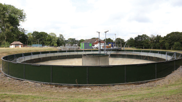
Brook Lane Pumping Station – Courtesy of Mott MacDonald
However, following constructability review with the contractor (MGJV), this section will also be constructed using HDD as a second inverted siphon in a similar configuration to the Brook Lane siphon. The pipe sections immediately upstream of the Brook Lane siphon and between the two siphons will have an operational regime, affected by the siphons. Hydraulic analysis has been carried out to determine the optimum configuration and the pipe size for the siphons, ensuring adequate velocities and at the same time minimising the risk of flooding.
Based on this, a 315 OD SDR11 PE pipe has been selected for the Brook Lane siphon and a 355 OD SDR11 PE pipe – for the second siphon. The gravity pipe sections between the discharge manhole and Brook Lane siphon and between the two siphons are designed as sealed pipes. Double orifice air valves are provided at each end of the siphons. The discharge manhole after the second siphon is provided with a vented cover.
Design elements: Brook Lane WwPS
Flow will be transferred to the existing Brook Lane Botley WwPS, from where flow is pumped to a second pumping station, Whiteley Road WwPS, before finally being pumped to Peal Common WTW. The existing 4 (No.) pumps at Brook Lane Botley WwPS are rated for the current incoming flow up to ~400 l/s in duty/assist/assist/standby mode and cannot accommodate the additional incoming flow from the new Botley Park WwPS. The existing pumps cannot be upgraded with larger impellers and motors either, and consequently new larger pumps are required. The new pumps will have similar body size however, and therefore the upgrade will require minor amendments to the pipework within the wet well.
The existing motor control centre (MCC) at Brook Lane Botley WwPS will be replaced to accommodate the larger pumps.
CAD element
The pipeline drawings were prepared in AutoCAD Civil 3D using data from the manhole, topographic surveys.
Archaeology and ecology
Archaeological assessment has found that there is the potential for the construction of the scheme to encounter archaeological remains of importance from different periods in history. For this reason a specialist archaeological contractor will be used during the construction phase to provide supervision and any specialist works required.
A preliminary ecological appraisal was undertaken in 2013 and detailed protected species and habitat surveys were undertaken throughout 2014. Surveys confirmed the presence of several bird species protected under the Wildlife and Countryside Act (1981) or identified as the being of conservation concern. Five badger setts were identified along the route and the presence of reptiles and bats was observed. There are three European-protected sites (SPA/SAC/Ramsar) within 2km of the scheme and a further 18 designated sites within 500m of the scheme including one statutory (Site of Special Scientific Interest) and 17 non-statutory designated sites (Sites of Importance of Nature Conservation).
There are likely to be temporary effects on these sites and mitigation measures have been defined, including directional drilling for the most sensitive locations together with a comprehensive mitigation strategy for ecological features. An Environmental Clerk of Works will be employed to oversee ecological aspects during construction.
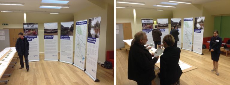
Public exhibition photographs – Courtesy of Mott MacDonald
Construction phase
Construction will be carried out by Southern Waters approved delivery partner for networks MGjv – a joint venture between Morrison Utility Services and Galliford Try. MGjv will be engaged under an NEC3 ECC Option C. Work is planned to start in April 2016.