
Euston 42” Trunk Main Diversion (Phase 1) (2018)
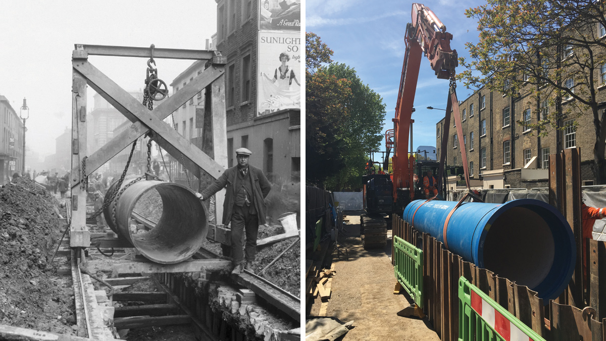
(left) The 42” main being laid (1925) - Courtesy of Thames Water (right) Pipe installation in Albany Street - Courtesy of SMB JV
High Speed 2 (HS2) Phase 1 will intersect a large number of critical third-party assets along its 190km route, with a significant impact on several of the UK’s water and wastewater companies. In London, approximately 50kms of Thames Water’s buried assets are affected by construction of the new railway, including a number of highly strategic clean water trunk mains. At Euston Station, an existing 42” diameter cast iron main must be diverted for 2kms to make way for the new high speed rail tracks and a major station expansion. Stantec UK are working closely with HS2 and Thames Water, through the eight2O alliance, to deliver Phase 1 of this diversion.
Introduction
In February 2017, the Hybrid Bill for Phase 1 of HS2 gained Royal Assent from Parliament, paving the way for construction of the UK’s new high speed railway. Enabling works for the project are underway, with main railway construction works due to start in late 2018.
Between Central London and the M25 motorway, the majority of the HS2 route runs in twin tunnels, passing beneath Thames Water’s assets at varying depths. At the south of the route, extensive upgrades are planned at Euston Station and within its approach cutting. The works to extend the station will directly impact a 42” strategic trunk main in several places, and construction of the new tunnels and portal within the approach cutting also threaten to cause unacceptable settlement to it. The 1925 pipeline is one of the top five most critical third-party obstacles along the HS2 route, and requires a 2km long diversion away from the impact areas.
Due to HS2’s programme, the pipeline must be diverted in two phases, with Phase 2 being constructed later within a designated multiple utilities corridor around the new station building. Phase 1 is a £17m, 1.4km diversion pipeline project and is currently under construction. As a result of its criticality to HS2, eight2O was awarded the design and construction of this project ahead of the appointment of a HS2 enabling works contractor. As it is relatively independent of the main HS2 construction work, this diversion is being delivered as a standalone Thames Water infrastructure project by the eight2O alliance.
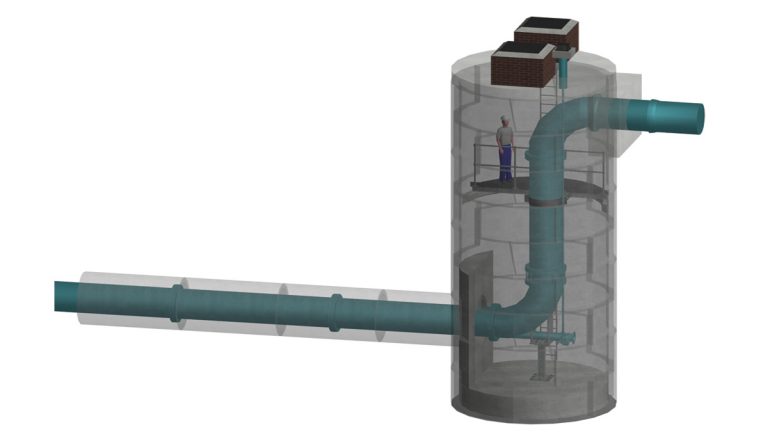
3D model of Shaft 1 in Park Village East – Courtesy of Stantec
History
The section of main to be diverted was constructed by the Metropolitan Water Board in 1925 as part of the original transfer route between the water treatment works in the west and Central London. The supply network in the city has been reconfigured a number of times since 1925, most notably through introduction of the Thames Water Ring Main (TWRM), and the 42” main is now a strategic feed into the Maiden Lane Flow Monitoring Zone, from the Barrow Hill TWRM Shaft.
The zone supplies a population of approximately 225,000 in a large area of North Central London, including areas such as Covent Garden, Kings Cross, Camden, Islington and Finsbury Park.
The existing pipeline consists of 12’ long, bitumen coated, 42” internal diameter, class D cast iron pipes connected using lead run, non-end restrained spigot socket joints. Non-destructive testing carried out as part of the project has indicated that the pipework is still in excellent condition, and since installation almost one hundred years ago, an average loss of wall thickness of only 2.8mm (7%) has occurred due to corrosion.
Diversion route
The route of the new pipeline runs from a connection point at the north end of Park Village East, doubling back on itself through the London Zoo car park to avoid the shallow decked, Grade II listed Gloucester Gate Bridge. The pipeline then runs along Albany Street, turning east into the Regents Park Estate and through to Cumberland Market, where the south temporary connection back onto the existing main will be installed. Although a significant undertaking, a temporary connection is necessary to clear the pipework from Park Village East and put Phase 1 of the diversion into service. This means that HS2’s works in the Euston approach cutting can commence, without waiting for the Phase 2 pipework to be installed.
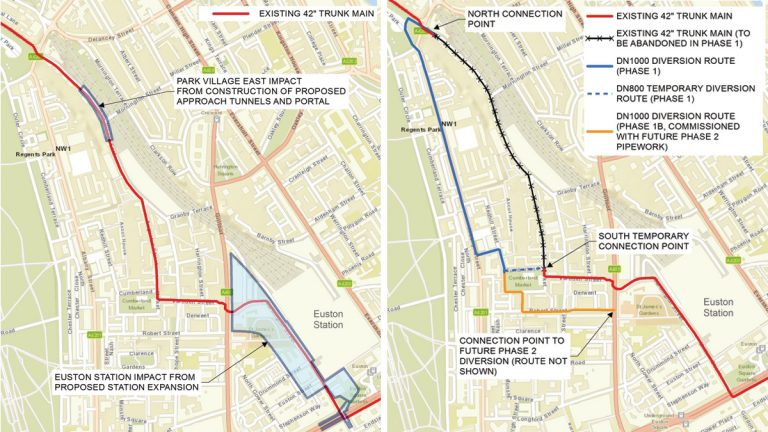
(left) HS2 construction areas impacting the 42” trunk main (flow is north to south) and (right) Phase 1 diversion route (flow is north to south) – Courtesy of Stantec
Finally, as part of the Phase 1 contract, a 425m long section of Phase 2 pipework will be laid between Cumberland Market and the east end of Robert Street. Effectively Phase 1B, this pipework will be installed and capped until Phase 2 of the diversion has been constructed. This section was included in the Phase 1 project scope to reduce the overall construction duration of Phase 2.
With the majority of the pipeline being installed by open cut trenching, finding a route through the utility congested streets of London which minimised the impact on various stakeholders was difficult to achieve, however, the real challenge in this project laid at the two connection points to the existing historic pipeline.
Euston 42” Trunk Main Diversion (Phase 1): Supply chain – key participants
- Project delivery: eight2O alliance *
- Designer: Stantec UK
- Main contractor: SMB JV **
- Principal sub-contractor: Kier
- Pipework supplier: Saint Gobain PAM UK
* The eight2O alliance is Thames Water’s capital delivery vehicle for AMP6 and is made up of eight partners: Thames Water, Skanska, Stantec, Balfour Beatty, Costain, Atkins, Black & Veatch and IBM.
** SMBJV (Skanska, Stantec, Balfour Beatty Joint Venture) is one of the two delivery joint ventures within the eight2O alliance.
North connection (Park Village East)
At the north connection point, the new pipeline connects to the existing 42” main at the north end of Park Village East. The justification for this centres around the complex arrangement of existing utilities within the Parkway junction, including a 36” branch from the 42” pipeline which feeds the zone’s reservoir. The other utilities in the junction include a second 36” trunk main, a 17” gas main, a 30-way BT duct, a bank of 66kV oil filled extra-high voltage cables, two high profile fibre optic cables and a large brick egg sewer. At this point, the 42” main dives down to a depth of 4m to cross underneath these utilities.
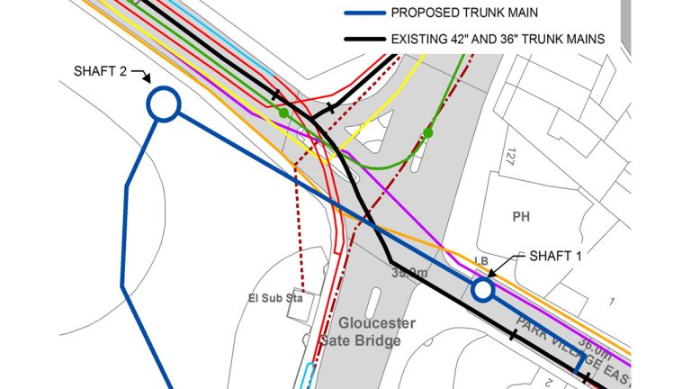
North connection arrangement showing the existing trunk mains and utility congestion in the Parkway junction – Courtesy of Stantec
Any connection or modification to the existing pipework in the junction would require a lengthy isolation of this critical trunk main and a large thrust block, which would have to be constructed amongst the high-risk utilities. This would introduce significant health and safety risks, cause major disruption, and reduce Thames Water’s network resilience in this critical area of central London during an isolation.
Therefore, a solution was devised by the design team which involves connecting at the location of an existing, relatively new valve in Park Village East, utilising the existing thrust restraint structure. From this point, a 1200mm diameter tunnel will be installed by microtunnelling under the Parkway junction between two 10m deep shafts, which will host a downsized section of new 800mm trunk main. This approach has minimised disruption and improved health and safety by avoiding all work in the junction. The drive shaft has been located in London Zoo carpark to avoid the listed Gloucester Gate Bridge and the infilled Regent’s Canal which historically ran beneath.
Installing a reception shaft in the narrow carriageway of Park Village East is particularly challenging as it contains a number of sensitive utilities including the 42” trunk main itself. In order to safely construct this structure, a complex temporary network reconfiguration has been agreed with Thames Water’s Operations team to isolate this section of trunk main for the duration of the works, mitigating the risk of a burst in the event of any accidental damage to the pipeline.
South temporary connection (Cumberland Market)
At the south temporary connection point, where the existing pipework to the north will ultimately be capped and flows diverted into the new pipeline, the 42” main operates at a maximum pressure of 5 bar. In pipework of this size, this pressure will generate a force of approximately 500kN at the capped end, which must be resisted to prevent the joints in the old cast iron pipework dislocating. A traditional mass concrete thrust block to resist this force was deemed to be too large, expensive to construct and disruptive to the local area. To mitigate these factors, a piled solution has been developed which significantly reduces the footprint of the work at this location.
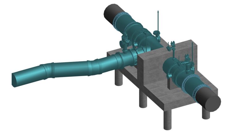
3D model showing the temporary south connection – Courtesy of Stantec
Installing this structure around a critical trunk main brings inherent risk, therefore a further series of network isolations have been agreed and a safe methodology for pipe installation developed through close collaboration between the design and construction teams.
To further complicate the solution at this constrained location, the design team identified an existing 2’8” by 2’4” brick egg sewer directly beneath the 42” water main. Following a gyroscopic survey of the sewer, it was identified that it would clash with the proposed pile cap. Therefore a sewer diversion was added to the project’s scope to secure the required space for the thrust restraint structure. This included the design of a 5m deep ‘backdrop’ manhole on to the existing sewer. This complex sequence of works has been communicated to the site team and key stakeholders using 4D BIM which merges the project’s 3D drawings and the P6 programme.
Pipeline material selection
The new pipeline will consist of a DN1000 fully restrained ductile iron pipe system. A number of different options were considered for the pipeline material, however, ductile iron was selected over steel and polyethylene due to the constructability issues associated with installing welded pipe systems in urban environments.
The design team secured acceptance of a technical waiver from Thames Water to use the innovative ‘Universal Rapid Ve’ boltless pipe jointing system from Saint Gobain PAM UK, which had not been used in the Thames Water network before. The current Thames Water framework system required bolts to be installed around the full circumference of the pipe, and the team decided to challenge its use as they were concerned about the risks associated with its installation on such large pipework in this constrained and utility dense area of Central London.
The use of this system will save hundreds of hours of confined space work installing bolts and tape wrapping. It will also reduce lifting and manual handling on site, reducing the likelihood of accidents. The system will also significantly reduce temporary works requirements around each joint, by removing the need for operatives to access under and around the large diameter pipework. This will in turn reduce the amount of excavation required around high risk utilities. These aspects will also increase productivity and allow project milestones to be achieved quicker on this key project.
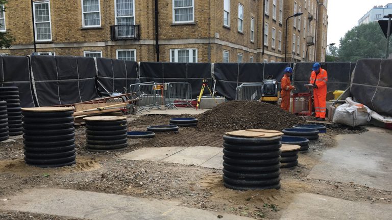
Pile sleeves installed around the existing trunk main in preparation for piling – Courtesy of SMB JV
Customer care
The pipeline route interfaces with a number of key stakeholders, including the London Zoo, two churches, the Regent’s Park Barracks, several schools and a significant local community. Therefore, customer engagement has been crucial in the period leading up to construction, which has been managed though a collaborative approach with HS2. Working in London Zoo’s car park is set to provide some unique challenges including having to safeguard the last remaining breeding hedgehog population in a central London park, and the removal and reinstatement of a Grade II listed wall and railings.
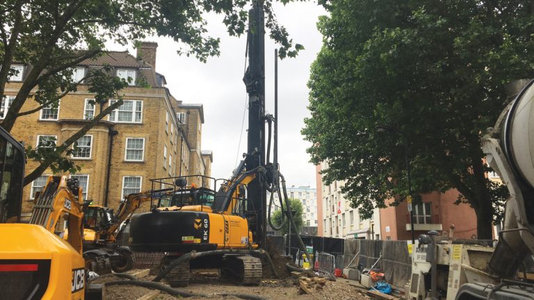
Piling operation to install piles for the south temporary connection – Courtesy of SMB JV
Summary
Through effective collaboration between the project team, Thames Water and HS2, this project is leading the way for the UK’s flagship infrastructure project. The significant challenges that the project has provided throughout the design phase have included technical, stakeholder and environmental aspects, which are sure to continue throughout its delivery. Works to construct the diversion commenced on site in January 2018 and are due to be completed in late 2019.