
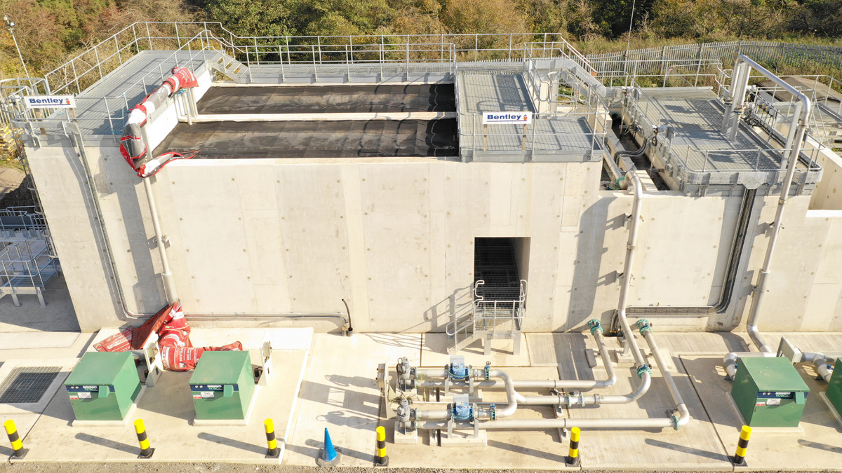
Pegswood STW (2019)
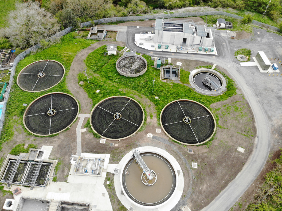
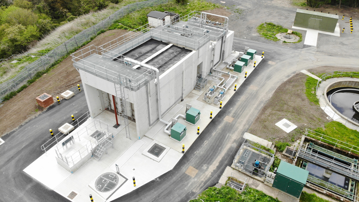
Pegswood STW: redundant and new primary tanks, and new sludge removal pumps (bottom left), existing biological filters, humus tanks and sludge storage (centre-ground); new tertiary treatment plant and MCC (top right) - Courtesy of MMB
Pegswood Sewage Treatment Works (STW) is a Northumbrian Water (NW) site located 16 miles north of Newcastle-upon-Tyne and 2 miles north-east of Morpeth, Northumberland. The treatment process comprised inlet screens, flow control and storm separation to storm tanks, two Dortmund pyramidal settlement tanks, four biological percolating filters, with a circular humus tank discharging final effluent to the Bothal Burn, a tributary of the River Wansbeck. The upgrade was included in Northumbrian Water’s (NW) AMP6 programme. The new quality consent required a new tertiary plant for removal of ammonia, and the plant was to be sized to accommodate development within the catchment over the design horizon.
Project drivers
There were three investment drivers:
- Quality (a tighter discharge consent): The Environment Agency had identified high levels of ammonia in the receiving watercourses and so included the site in its National Environment Programme, requiring the discharge of ammonia in the treated effluent to be reduced from 7 mg/l to 3 mg/l by the end of March 2018.
- Population growth: The contributing population was forecast to increase by 10% within the design horizon and there was insufficient process capacity to treat the additional load.
- Operational/maintenance issues: The works was already performing poorly due to inadequate performance of the existing primary settlement tanks, resulting in increased load passing onto the downstream treatment process, placing the works at risk of failing its consent. Final effluent was therefore being temporarily over-pumped to a ‘polishing’ stage comprising a mobile HSAF (hybrid submerged aerated filter) operating in solids filter mode to reduce suspended solids and associated biological oxygen demand (BOD) prior to discharge. An improved primary settlement stage was therefore required.
Investigate and define phase (I&D)
In November 2015 Mott MacDonald Bentley (MMB) was appointed to investigate and define the issues and solution under NW’s AMP6 Runway 2 Design and Construct framework. MMB confirmed that replacement of the two existing Dortmund primary settlement tanks with a more efficient circular settlement tank, together with tertiary treatment comprising a nitrifying submerged aerated filter (NSAF) and deep bed filter (DBF), would ensure compliance with the new consent.
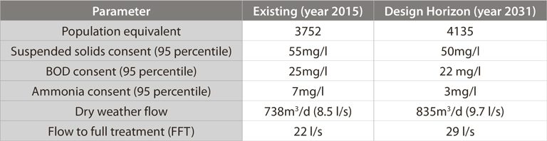
Pegswood STW – Parameters
NSAF/DBF
The longest lead item in the construction programme was the tertiary plant. This was a relatively compact but complex structure with variable wall heights, deep compartments, elevated cantilevered channels, baffled chambers and interconnected pipework. An in situ concrete design would have incurred significant challenges in construction, with the need for a significant proportion of working at height, substantial and complex temporary formwork, and a substantial quantity of site-fixed rebar.
Programme and cost comparisons showed that a precast concrete (PCC) solution would be a very cost-effective construction method. Advantages included off site pre-fabrication of the PCC units, improved quality control and buildability, reduced wall thicknesses, reduced construction programme, overall reduced costs, and improved health and safety.
Critically, the programme savings for a PCC design would allow the project to meet the new consent date with greater certainty.
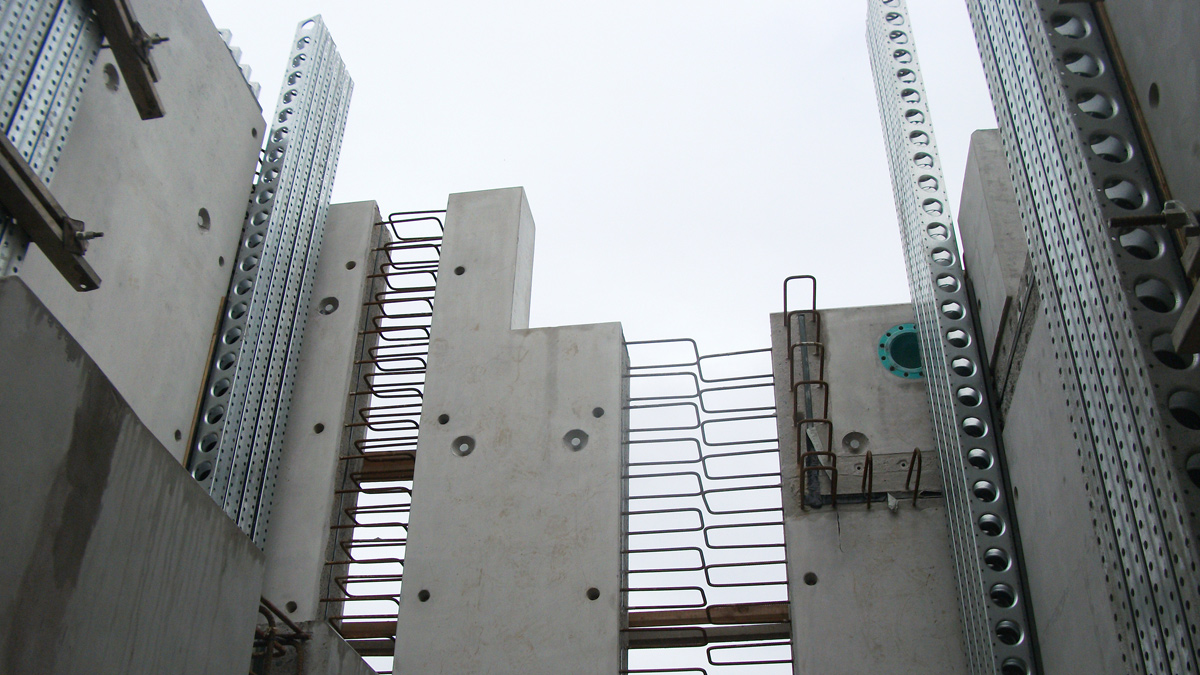
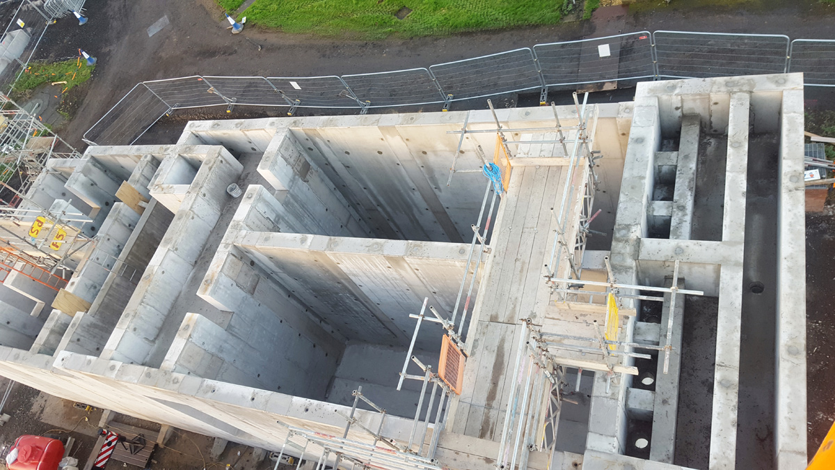
PCC wall panels for NSAF/DBF structure showing stitch joint reinforcement and shutter system – Courtesy MMB
The works site was already congested with process tanks and buried services, but the new tertiary plant could be located on the footprint of redundant sludge drying beds near the works outfall, bringing back into beneficial use a previously disused part of the site.
The drying beds were recessed into a sloping part of the site and had a perimeter road. Ground investigation boreholes showed rock-head to be within a metre of the base. It was decided to found the new tertiary plant at ground level by removing the ground over a plan area of 277m2 and replacing it with imported granular fill compacted to provide a firm foundation.
The NSAF plant ranged in height from 4.5m above finished ground level to 6.7m at the inlet. A low-lift interstage pumping station was required to raise secondary treated effluent from the existing humus tank to the new tertiary plant.
An off site built pre-assembled pump station and associated valve chamber were chosen: the chambers were of GRP and came complete with internal pumps, guide-rails, pipework and valves fitted.
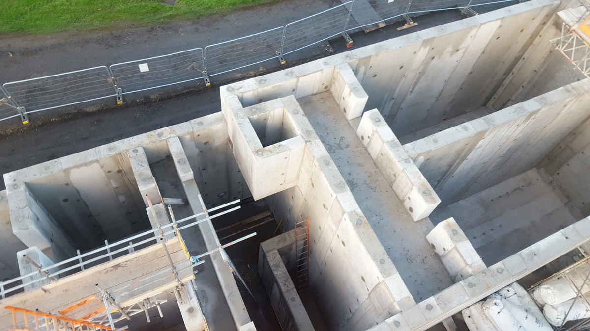
PCC was effectively used to form the complex shapes of the NSAF/DBF structure – Courtesy MMB
In agreement with the process supplier, MMB designers altered the proposed layout of the new tertiary plant to allow it to fit within the available space and existing road layout. The mechanical plant was sited at ground level immediately adjacent to the structure, so the road provides ready all round access for Hiabs and cranes to the process blowers and pumps, the interstage pump station and valve chamber, for future maintenance and replacement.
Since the process plant contains relatively small diameter pipework, filter distribution system nozzles and the media, the secondary treated effluent was to be screened in order to protect the plant from blockage by extraneous fines.
Unlike other sites where screening has been provided at high level, at the inlet to the NSAF, the MMB design opted to pass the flow through a 6mm static peak screen in a chamber immediately upstream of the interstage pumping station, so that the screen could be readily inspected and cleaned from ground level.
The pumped flow was split and passed through two NSAF beds and then two DBF cells, before being discharged via a wash water storage well to the existing outfall.
PCC NSAF/DBF structure nearing completion – Courtesy MMB
Primary tank
The only possible location for the new primary tank required the diversion of numerous buried and several uncharted services including:
- The gravity feed to the existing filter beds.
- Electrical and ICA cables.
- Washwater and humus sludge return mains.
- The storm overflow sewer.
- Demolition of a redundant storm overflow measurement flume.
During the define phase a Customer Engagement Plan was developed to mitigate the effects of construction activities on the neighbourhood, residents, adjacent allotment holders, and recycling centre, keeping them informed of progress and, for example, ensuring that the narrow shared vehicular access to the site would not be obstructed.
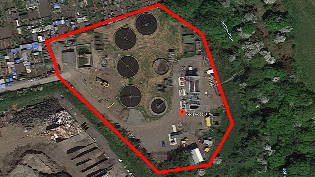
Pegswood STW showing the site boundary and neighbouring land use – Image from Google Earth – Courtesy MMB
Since there was an obligatory legal date for meeting the new discharge consent, the work was programmed to be carried out in two phases:
- Provide tertiary treatment for the removal of ammonia.
- Provide the improved primary treatment performance.
An NEC Option C contract for Design and Construction (D&C) of the project was awarded with a target cost of £1.6m for the new NSAF/DBF and £0.84m for the new primary tank (totalling £2.44m).
Design and construction phase (D&C)
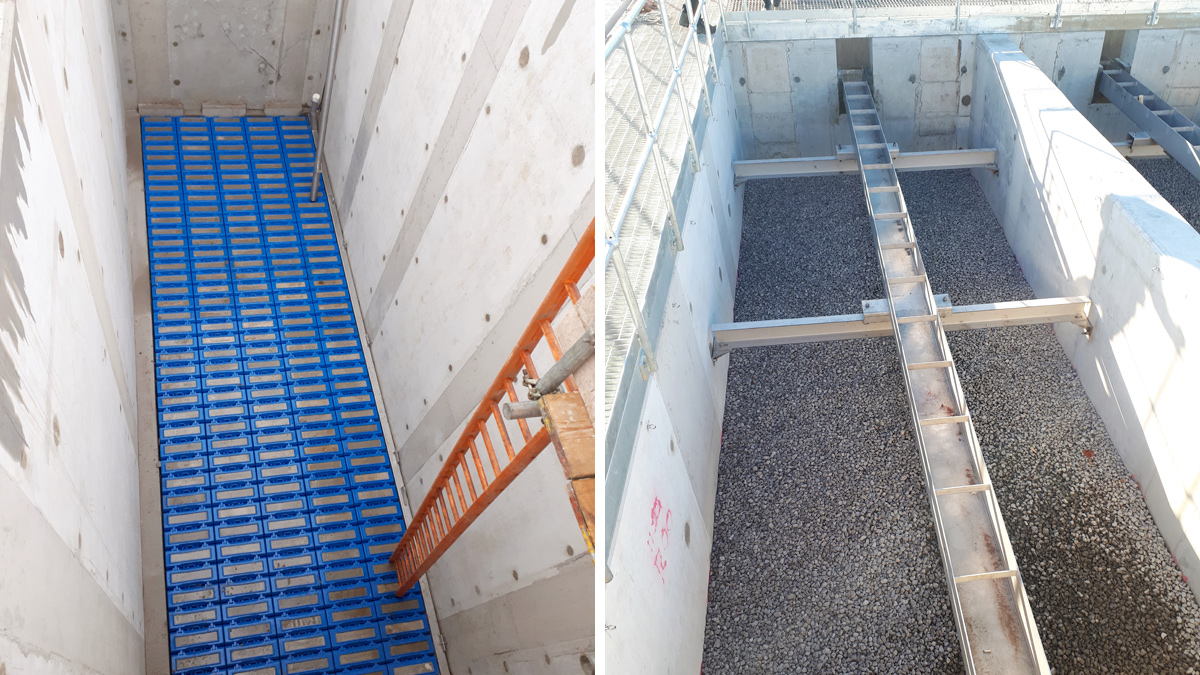
(left) NSAF filter cell floor: Combined flow/backwash distribution system and (right) media in the NSAF cell: Combined inlet/backwash launder channel – Courtesy of MMB
MMB had recently designed and commenced construction of another new NSAF/DBF tertiary plant at a larger Northumbrian Water site (East Tanfield Sewage Treatment Works, County Durham, PE 21,337 – Refer to UK Water Projects 2018 pp.188), from which learning and efficiencies were passed on to the Pegswood D&C team. These included:
- Off site PCC build for the NSAF/DBF structure, not only affording reduced exposure to site-based health and safety risks but also increased quality control (factory produced units), cost reductions (slimmer wall thicknesses hence less concrete) and reduced site installation programme (also reducing the site establishment costs).
- Commonality of process and precast concrete suppliers for the plant.
- The Pegswood construction team visited the East Tanfield project to witness the installation of the PCC wall units, so gaining valuable experience before installation on their site.
- To minimise the need for temporary high-level access over the walls and into the tanks whilst installing internal components, a number of 1000mm wide ‘stitch’ joints, without projecting starter bars, were left uncompleted so that construction workers could enter the tanks at ground level until most of the internal work had been completed.
- To further reduce working at height, flanged pipe inserts were cast into the PCC wall units at the required positions, to facilitate later high-level pipework installation.
- A revised formwork system was used for the in situ concrete stitch joints between PCC wall units, allowing quicker installation and removal times.
- A 10mm aggregate concrete mix was specified to fill the 450 wide in situ ‘stitch joints’ between adjacent PCC wall panels. The mix was designed to allow the full height of a joint (up to 6.7m tall) to be poured continuously in one lift. An added bonus was that the increased rate-of-gain in strength of the mix allowed formwork to be stripped earlier after placing, so a quicker turnaround of formwork and joint completions.
Static screen chamber, interstage feed PS (foreground), new NSAF/DBF plant in operation (centre) and new MCC Kiosk (top right) – Courtesy of MMB
With little space around the perimeter of the NSAF plant and the need to maintain operational vehicular access for tankers to an adjacent sludge tank, a concrete blinding 200mm thick provided not only a level surface for the PCC wall units but also support for the 100t mobile crane required for placing them.
The free-standing full-height PCC wall units (up to 6.7m high) were called off and delivered to site in the order required for construction on a ‘just in time’ basis, to match a pre-determined installation sequence working out from the furthest point, so avoiding site storage and double-handling.
The wall units came with exposed lapping rebar, pre-scabbled concrete faces and ready-fitted hydrophilic strips at each in situ joint location, removing the need for any on-site preparation of the in situ joints. The in situ wall joint concrete was placed at a rise-rate of 2m/hr. All units were installed in just two weeks, with the in situ base slab and wall joints completed within the following month. Good workmanship and the high quality of the in situ joints meant that each tank compartment passed its water test first time.
Weekly CLIP and coordination meetings with client operators, sub-contractors and suppliers underpinned the effective coordination required to fit out the access metalwork, process plant, pipework, monitoring instruments, power and signal cabling, and control panels by the respective sub-contractors, and commission the plant to meet the compliance date.
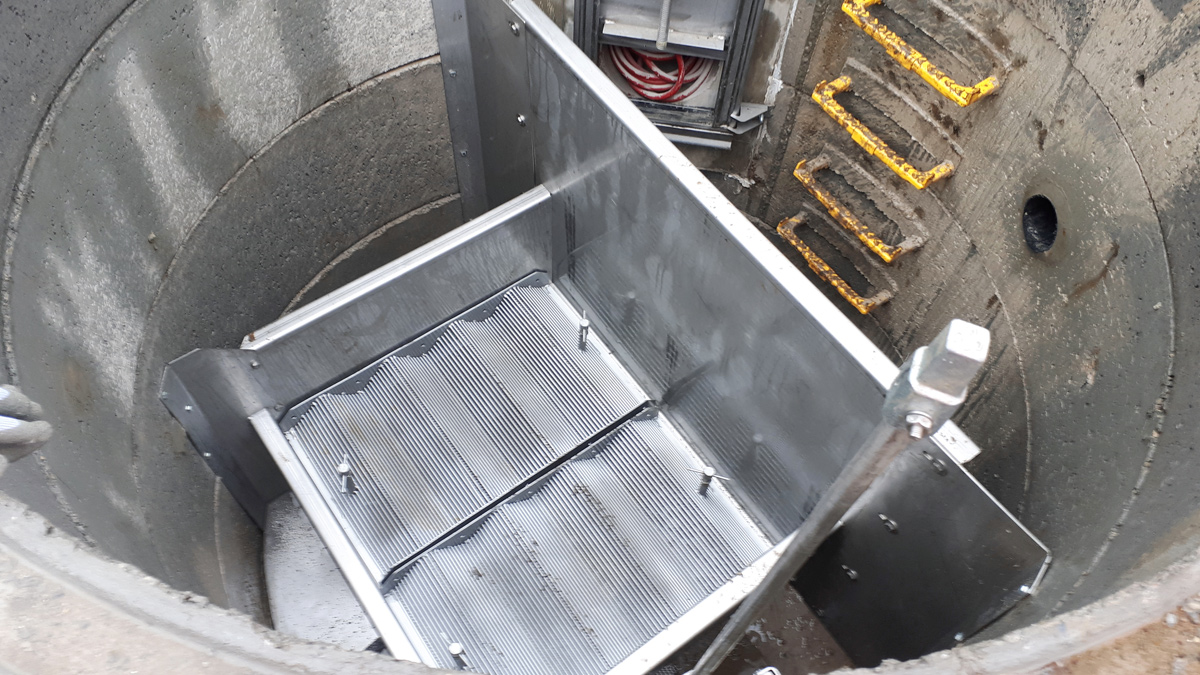
6mm static peak screen protection for the NSAF – Courtesy of MMB
Programme
The D&C contract was awarded in March 2017, with the new tertiary plant required to be meeting the new discharge consent by 31 March 2018. The construction team mobilised to site in June 2017 and the plant was commissioned in February 2018, ahead of the consent date. Completion of the whole contract, including the new primary tank, took place in November 2018.
Pegswood STW: Supply chain – Key participants
- Client: Northumbrian Water
- Principal designer & contractor: Mott MacDonald Bentley
- Precast concrete tank design & supply: FLI Carlow (now FLI Precast Solutions)
- In situ reinforced concrete & shuttering: Crestfix Ltd
- Nitrifying submerged aerated filter (NSAF) & deep bed filter (DBF) process design & plant: De Nora Water Technologies UK Services
- Packaged pumping station & valve chamber: Xylem Water Solutions UK
- Temporary works (shoring for primary tank): MGF
- Primary tank system formwork: EFCO
- Galvanised mild steel access metalwork: JHT Fabrication Ltd
- Half bridge scraper: George Green (Keighley) Ltd
- Control panels: TES Group Ltd
- Control panel kiosks: Northern Pump Supplies
- Precast concrete U-channels: Wolfenden
- Systems integration: IDEC Technical Services
- Power supply & electrical installation: Dimewest Engineering
- Kiosks: Industrial GRP Ltd
- Mobile cranes: Mammoet
- Acoustic survey: Paul Horsley Acoustics Ltd
6mm static peak screen protection for the NSAF – Courtesy of MMB
The use of a 3D model and the adoption of Off Site Build (OSB) and Design for Manufacture and Assembly (DfMA) contributed significant savings to the programme. The interstage pumping station and valve chamber were provided as GRP chambers pre-fitted with pumps, guide-rails, internal pipework and valves, ready for installation and interconnection.
The 3D model of the tertiary plant was used to agree the layout for both the PCC solution and the metalwork access platforms and stairs, and was used in the design, approvals and fabrication for both items. Metalwork fabrication progressed in parallel with site civils construction so that it could be delivered to site in pre-assembled sections ready to be craned and fixed directly into position.
The 3D model was also used for detailing and visualising the rebar for the new primary tank.
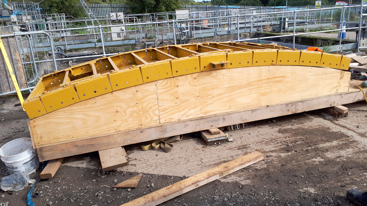
Proprietary formwork shutter system being set up to match the PST wall radius – Courtesy MMB
Ground conditions & temporary works for the primary settlement tank (PST)
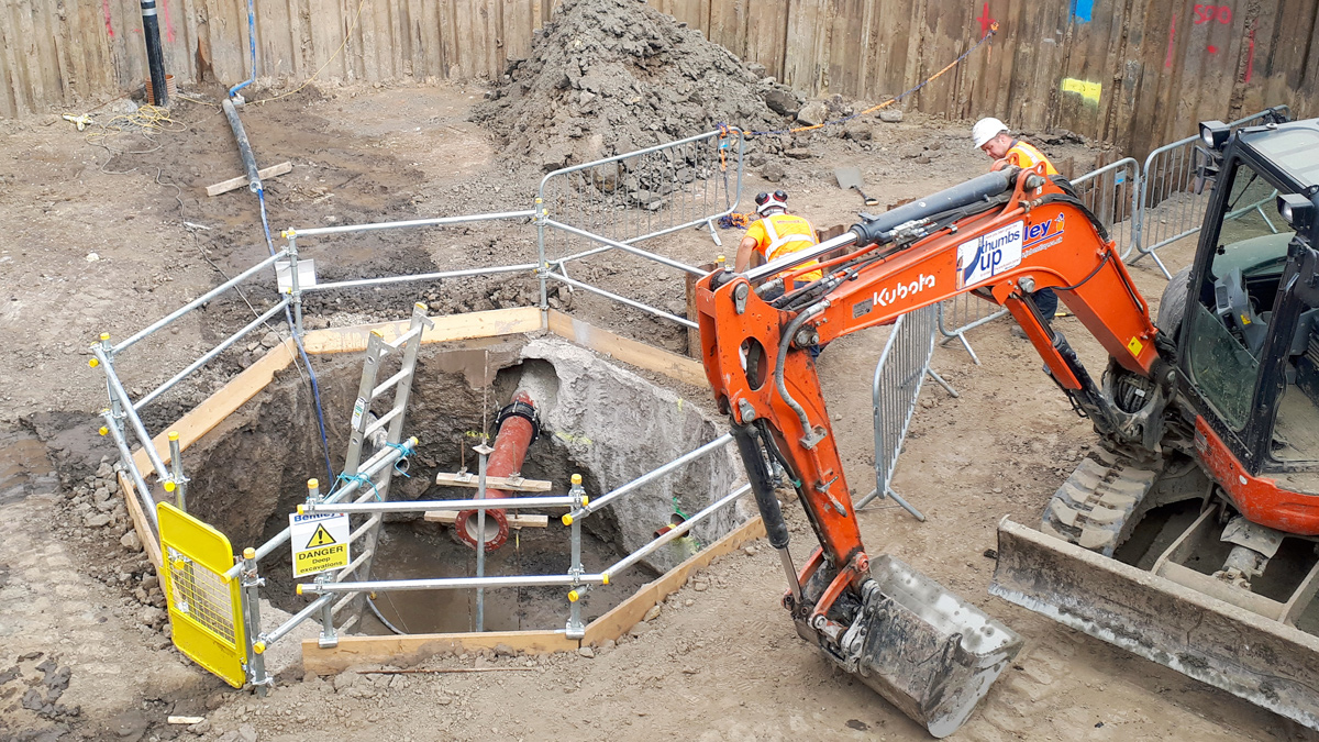
A 4 m deep hexagonal-shaped temporary cofferdam was installed within stiff to firm clay, with sheet piles toed in and a single internal brace.
A 21t excavator was used to carry out the bulk dig whilst a 5t excavator was placed inside to complete the dig to formation level. At this level, the 5t excavator was fitted with an auger to cut and excavate a 2m deep circular trench which was filled with concrete and A393 mesh to provide temporary ground support for excavation and construction of the central reinforced concrete sludge hopper.
A concrete base was poured with a specially made inverted timber cone to form the central sludge hopper containing effluent inlet and sludge removal pipes.
The formation was trimmed to final slope, blinding concrete and base rebar placed, and the concrete base poured. A cost-effective way of constructing the tank walls was in two near full-height circumferential halves followed by completion of the top in a single continuous pour.
The curvature of the wall formwork system was set to achieve the required internal tank radius and was used twice to form both the first and second halves of the tank. After the first pour the vertical stop ends were stripped and retarder washed off to avoid the need to scabble the construction joints.
The new Pegswood STW primary settlement tank was successfully water tested first time. It was then backfilled, the temporary works were removed, the upstream and downstream pipe connections were made, and the half bridge scraper fitted by George Green (Keighley) Ltd.
NSAF/DBF process being commissioned – Courtesy of MMB
Conclusion
The new tertiary plants at both East Tanfield and Pegswood were both commissioned and meeting their new consents by the required end date of 31 March 2018.
East Tanfield Sewage Treatment Works is generally achieving a final effluent ammonia value of 1 mg/l and phosphorous of 0.5 mg/l. Pegswood is generally achieving an ammonia value of less than 0.21 mg/l, BOD less than 3.5 mg/l and suspended solids less than 3.0 mg/l.