Plas Uchaf Reservoir (2022)
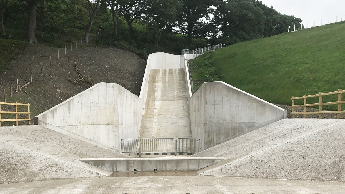
Looking up the spillways chute - Courtesy of Skanska
The construction of Plas Uchaf Reservoir was completed in 1870. It has an embankment dam that is approximately 15m high, with a puddle clay core. It has a retained capacity of 225,500m3 and a surface area of 3.5ha. The reservoir is formed across a tributary of the River Elwy, with Dolwen Reservoir located approximately 0.7km upstream of Plas Uchaf. In July 2013, the statutory section 10 inspection (at least 10 yearly inspection), identified the requirement to investigate whether the capacity of the overflow spillway could safely pass the probable maximum flood (PMF). The study carried out by Arup concluded that the overflow spillway was inadequate and reservoir safety improvements were required.
Investigations
Following a feasibility study exploring possible options to increase the overflow capacity, it was recommended that the spillway was enlarged and replaced along the same alignment as the existing structure. To enable this construction, the water level in the reservoir would need to be reduced with the level controlled using the supply siphons and/or the scour pipe. However, further investigation found that the footprint of the new spillway would clash with existing siphon valves and pipework at the toe of the dam, requiring the siphon valves and pipework to be relocated.
Therefore in addition to the clash mentioned above, the limited resilience to provide supply to the Glascoed WTW downstream and the lack of emergency reservoir drawdown capability, Welsh Water opted to add the replacement of the siphon and scour pipe and valves to the project scope.
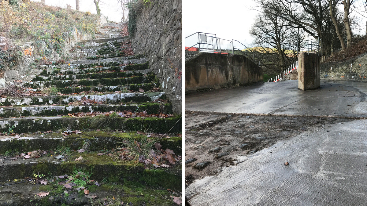
(left) Existing spillway and (right) image showing existing access shaft – Courtesy of Skanska
Spillway design
Existing spillway overflow
The spillway consisted of a 11.63m flat crested weir, with a crest level at 144.65mOD. It is located at the right abutment of the dam. This weir discharged into a concrete channel that transitioned to a steep 4m wide stepped spillway channel with masonry side walls.
At the downstream toe, floodwater was conveyed through a masonry lined horseshoe shaped culvert (1.32m wide by 1.27m high with an arched roof) and returned to the original water course 179m downstream.
The access shaft to the upstream end of the supply tunnel was located in the centre of the spillway having been extended up to dam crest level by a hexagonal reinforced concrete shaft. The shaft was connected to the dam crest by a narrow footbridge.
Design consideration of new spillway overflow
Several options were identified to comply with the design and safety criteria defined in the Floods and Reservoir Safety 4th edition and to ensure Plas Uchaf dam could safely pass the PMF. Many of these options were ruled out on the basis of technical viability and cost, leaving three options, which were taken forward for a more detailed evaluation.
- Option 1 involves retaining part of the existing structure and amending it to increase conveyance capacity and make it structurally sound.
- Option 2 involves construction of a new reinforced concrete spillway on the same line as the existing spillway.
- Option 3 involves removing the existing spillway and constructing a new reinforced concrete spillway in a separate location, passing directly over the dam crest and discharging at the toe of the dam.
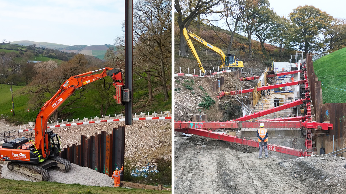
(left) Sheet pile installation and (right) temporary propping installed – Courtesy of Skanska
Each of the three options were evaluated against a scoring matrix to determine the most favourable solution. Evaluation considered 11 weighted criteria including capital cost, constructability, visual impact, sustainability, maintenance, health and safety, and flood risk. Option 2 was determined as the preferred option and was recommended to be taken forward to detailed design.
An additional consideration was that the stilling basin must reduce the existing flow velocities significantly enough that the PMF event would not cause downstream erosion that could affect the stability of the dam or spillway.
New spillway overflow
The new overflow spillway consisted of a spillway forebay that channels flow from a 15m wide entrance weir. This reduced in width to 5.5m at the top of the chute. The 5.5m wide cute discharges in to a 9m long stilling basin. The stilling basin then channels low flows in the existing downstream culvert via a new stilling chamber, and discharges high flows overland through an embankment channel into the downstream field.
Siphons and scour pipe
There was no gravity feed to the reservoir from any indirect catchment, but water was regularly pumped into the reservoir from the River Elwy. Water from the reservoir gravitated to Glascoed WTW and was the main source of supply. A supplementary borehole supply was used to balance water quality issues and peak demands.
Siphons installed on the face of the dam and through the dam – Courtesy of Skanska
There were five siphons over the top of the embankment dam [1 (No.) 150mm diameter CI 1 (No.) 200mm diameter CI 3 (No.) 300mm diameter uPVC), which were used for both supply to the WTW and as a method of part-drawing down the reservoir. However, the existing siphons were in poor conditions with only one siphon working.
A feasibility study was carried out by Arup resulting in a long list of options to determine which solution to progress. Options 3a and 4c were combined to form the final solution and meet the project objectives, particularly:
- Supplying the required quantities of raw water to Glascoed WTW.
- Meeting the new drawdown guidance.
- Ensuring the enabling works would be completed in time to not affect the construction of the spillway.
The preferred solution was the installation of two new siphons across the centre of the dam and the replacement of the existing scour pipe with a larger diameter pipe within the dry section of the tunnel. One of the project constraints was that during installation of the new pipework, the maximum WTW shutdown should be 12 hours in the summer and 20 hours in the winter, unless additional sources of water were arranged.
Plas Uchaf Reservoir: Supply chain – key participants
- Client: Dŵr Cymru Welsh Water
- Principal contractor: Skanska
- Civil contractor: William Hughes Civil Engineering
- Lead designer: Arup
- Geotechnical investigation: Geotechnics Ltd
- Temporary works: MGF Ltd
- Piling contractor: Ivor King (CEC) Ltd
- Diving contractor & emergency siphons: Edwards Diving Services
- Landscaping: Man Coed VM Ltd
- Ground investigation: Quantum Geotechnic Ltd
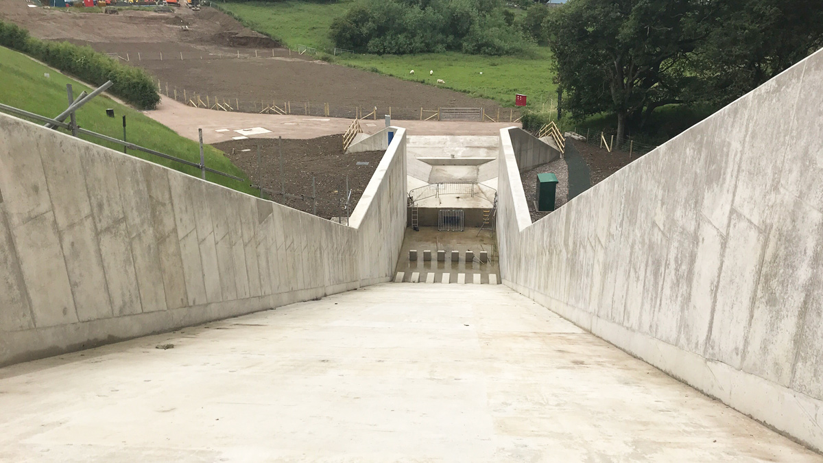
Looking down the spillway chute and into the stilling basin – Courtesy of Skanska
Construction
Construction constraints
The location of Plas Uchaf Reservoir provided unique challenges to construction. Due to the rural location of the reservoir, the largest vehicle that was able to get to site was a 40T excavator. In an ideal situation, a project of this scale would also require a crane, however this was not possible due to the access restrictions. Furthermore, several of the deliveries had to be escorted along the country lanes to site by the sub-contractor due to their size.
Another challenge the project had to manage was the proximity of the neighbours which was managed by Welsh Water Estates team.
Constructing the new spillway
Access around the existing spillway was very limited, as such, a haul road had to be built to the right-hand side of the existing spillway prior to starting construction on the spillway.
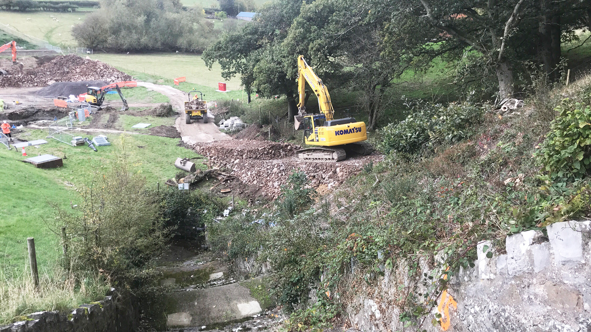
Haul road created to the left-hand side of the spillway – Courtesy of Skanska
Construction started at the top, stating with the 15m wide forebay. This was then followed on by the chute; sheet piles were installed either side of the existing spillway. This allowed temporary props to be installed, following this, the excavator was then able to track down the left-hand side of the spillway, if you are looking downstream. This allowed the existing spillway to be removed and excavation down to the new formation level before building back up to base slab and wall slabs. It also allowed the installation of the back of wall drainage, shear keys and cross drainage.
Prior to the chute walls being constructed, the access shaft was raised and a new pedestrian footbridge installed, allowing the excavator to reinstate the access on the left hand side as the wall construction progressed downstream.
Constructing the siphons
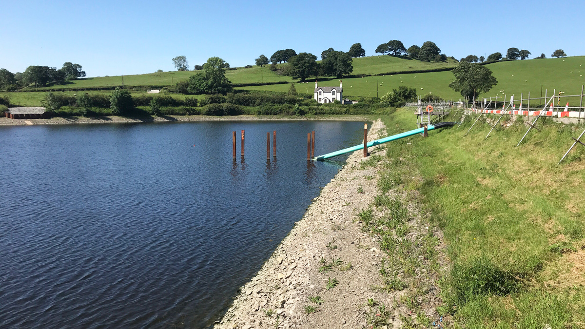
Having to install siphons on a reservoir in which we could not reduce the water level required out of the box thinking. Piling sub-contractor, Ivor king CEC Ltd, installed a barge in the reservoir. This was anchored to the side of the dam to avoid the barge moving and colliding with the live siphons (which fed Glascoed WTW). Edward Diving Services used divers to move pitching stone, to enable the installation of the piles. From the barge, it was then possible to install piles using a 30T excavator with a piling hammer. Crossbeams were installed on these piles. Then siphons were then connected to the crossbeams. A Spider Excavator was used on the downstream face of the dam to excavate a channel for the siphons on the downstream face. It was cut into steps, to reduce the risk of slippage.
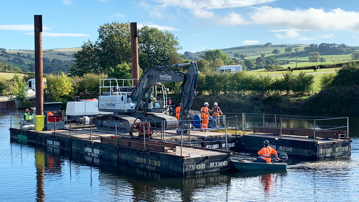
Barge used to complete the piling – Courtesy of Skanska
COVID-19 impact
As with many construction projects, that were live in March 2020, Plas Uchaf Reservoir was impacted by the changes brought on by COVID-19 and the project suffered a 6-week delay. This was due to inefficiencies brought about to self-isolating staff and having to maintain a 2m distance between personnel: for example, carpenters could not work in the same area of the steel fixers for some of the wall sections.
Conclusion
This project was possible due to the collaboration of all involved. The location in a remote part of north Wales, with limited access provided a challenge, the limited working space available and working on a reservoir that had to be kept live was also a huge challenge. This project has brought resilience into the system and is confident it meets the requirements for dam safety.
In addition to building a new spillway and installing new siphons and a scour valve, the project also created a new bat cave and carried out landscaping in the area to meet the planning constraints.