
Preston WwTW (2018)
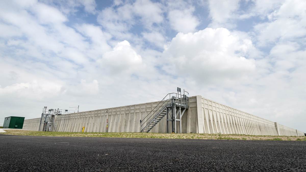
New storm tanks at Preston WwTW - Courtesy of MMB
Preston WwTW serves a population in excess of 250,000 and has six sub-catchments: Lytham, Fairhaven and Freckleton within the Fylde District to the west, Lea Gate and Watery Lane to the east within the Borough of Preston and Penwortham to the southwest within the South Ribble District. United Utilities (UU) has invested £20m during AMP6 at Preston WwTW and in August 2015, awarded the Preston Storm Tank Project to specialist design and build contractor Mott MacDonald Bentley (MMB). The project’s objectives were a reduction of storm water spills and improvements to both the underperforming inlet works and the primary settlement stage. The project has been handed over to United Utilities operations staff, and contract completion was 31 May 2018.
Project background
All of the inflows to the WwTW are pumped and the catchment generates high concentrations of screenings, particular during storms after long dry periods. Recently the existing inlet works has struggled to deal with the peak screenings load, exacerbated by the many recent UID projects undertaken within the sub-catchments.
Measures to provide improved operability and resilience at the inlet works were essential. Route cause and analysis techniques were adopted to ensure the best outcome.
Additional storm storage capacity was required to meet the AMP6 three spills per bathing season and ten spills per annum (shellfish) drivers; spill performance being averaged over a fifteen-year period to a 2036 design horizon, that included for climate change.
Maintenance scope requirements were identified following asset surveys and a review of operational maintenance reports.
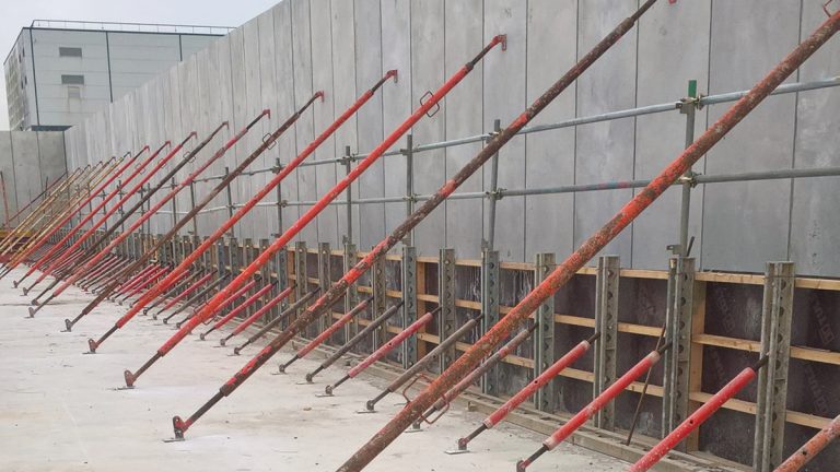
Temporary propping of the PCC wall unit prior to pouring of the in situ ring beam base – Courtesy of MMB
Scope of works
The scheme components include:
- New storm tanks with a combined capacity of 51,000m3.
- Storm tank fill and emptying pipework.
- Flow to works measurement.
- Concrete repairs to the primary settlement tanks (PST) numbers 1-8.
- Mechanical and electrical refurbishment to PSTs numbers 1-8 including replacement scrapers.
- Improvements to the existing under-performing elevated inlet works.
- All associated electrical, control and telemetry works.
- Landscaping.
Site constraints
The Preston WwTW site is located on the northern bank of the River Ribble estuary and is surrounded by areas of historic and current land fill. A desktop study also identified that areas within the WwTW have previously been used as landfill sites. The western end of the treatment works footprint, closest to the location of the proposed storm tanks, was known as Grange Farm, with the northern end being named Clifton Marsh. The site is within an area designated as being at risk of both tidal and fluvial flooding.
The Ribble Estuary adjoining the treatment works site is designated as both a Ramsar and a Special Protection Area, under European and UK legislation.
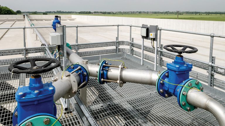
View down the completed storm tanks from the access platform – Courtesy of MMB
BIM and information management
The Preston Project was delivered to a full PAS 1192-2 information delivery cycle. A clear defined Employers Information Requirements (EIR) was in place as part of the contract. A BIM Execution Plan (BEP) was developed to address the EIR and explain how the information modelling aspects for Preston would be carried out. Included in the BEP was a Master Information Delivery Plan detailing when project information was to be prepared, by whom and using what protocols and procedures.
Data developed during the design and construction phase of a project – the Project Information Model [PIM] – was progressively developed and delivered to UU, to coincide with their decision-making processes as defined by the EIR. The asset centric PIM was prepared, compiled and delivered on UU’s BS1192 configured Common Data Environment (CDE) – Bentley ProjectWise. The Asset Information Model (AIM) including health and safety documentation, operation and maintenance data and as-constructed information including 3D models where all delivered through the CDE in a structured and defined process documented in the EIR, enabling UU to maintain the AIM through the lifecycle of the assets constructed during the Preston WwTW project.
With Preston being a collaborative 3D BIM project, a federated model was compiled by amalgamating several different models from MMB, GHD and Longwood into one. The advantages included:
- Earlier design coordination and development.
- More efficient clash detection and avoidance during the design process.
- Efficient tool for design review, buildability and temporary works design.
- Enabled faster design iterations and streamlined historically time-consuming tasks.
- Allowed metadata to be added to existing services, confirming the accuracy of their geospatial position from inaccurate historical drawings to positions verified by trial trench data.
- Provided setting out data direct from the model to the site team’s survey equipment.
- Effective visualisation for the whole design and site teams.
Autodesk’s Civil 3D was used extensively through the design stage for storm return pipework development, where large diameter pipework had to be threaded through a site heavily congested with services.
The Access, Lifting and Maintenance (ALM) review for the inlet works was carried out utilising the federated model. This allowed the whole project team and client to interact with information in a 3D format. The use of a virtual reality headset was adopted, providing a new way to engage and review spatially accurate information, deliver a safe design and ensure ease of future operation and maintenance.
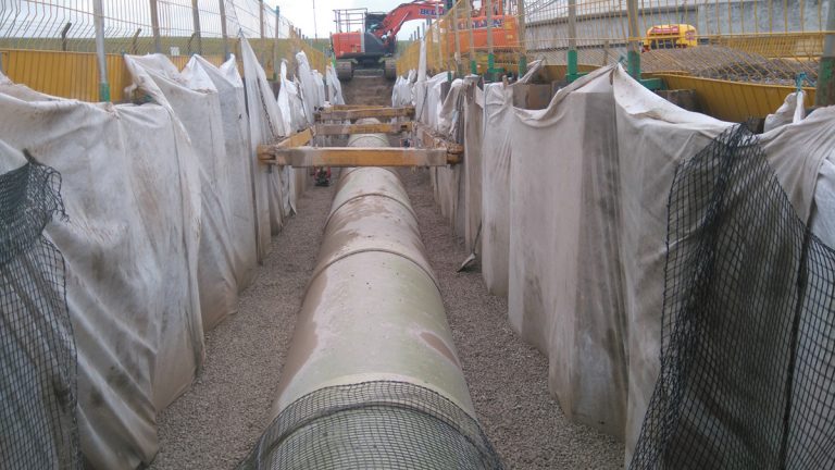
Laying new GPR pipeline – Courtesy of MMB
Scheme optimisation
Additional storm storage was required to supplement the existing 64,140m3 storm tanks to meet the reduced spill frequency requirements and also replace the structurally derelict 1938 storm tanks that have a capacity of 13,400m3.
During the solution development stage, major CAPEX savings were realised in comparison with the tender design. These savings included:
- Storm tank volume reduced by 25% to 51,000m3.
- Requirement for well point dewatering eliminated.
- Storm tank compartments reduced from three to two.
- Requirement for stabilisation of excavated soil eliminated.
The storm tank volume reduction was realised following extensive development and dynamic optimisation of the network model. This included amendment of the real time control functionality of the existing Preston Storage tunnel (40,790m3), matching the existing pass forward flows, whilst also ensuring no detriment to the existing network CSOs.
Furthermore, the model was optimised to better reflect the efficient storm return system, modelling the variable speed pumps feeding in when flow to works drops below flow to full treatment (FtFT).
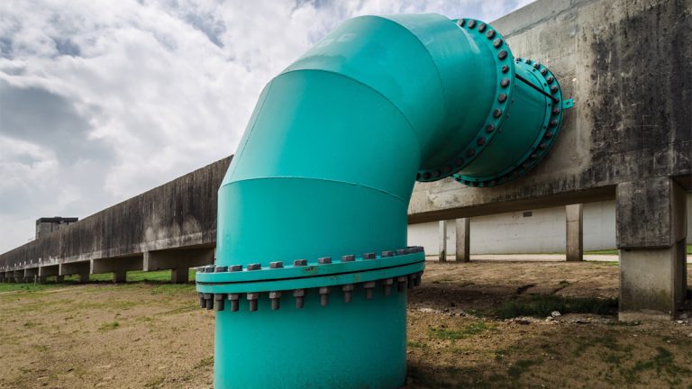
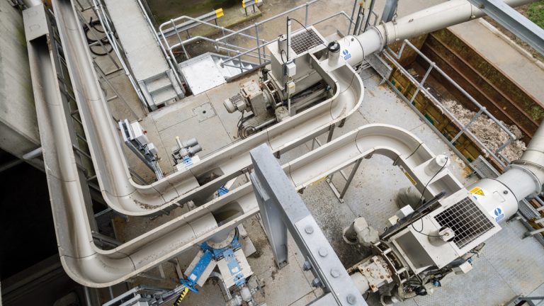
Connection between new pipeline and existing elevated inlet structure – Courtesy of MMB
Early in the design process it was recognised that due to potential contaminated soils and high ground water levels, a key objective was to reduce the depth and volume of excavation. A significant amount of additional ground investigation was carried out to better understand the ground conditions and behaviours of the water table. Adoption of a large footprint tank with reduced depth together with a better understanding of the groundwater allowing the elimination of well point dewatering.
The reduction in anticipated dewatering was also welcomed by UU, as the potential discharge of additional ground water flows containing elevated ammonia levels into the treatment stream was raising concerns.
The provision of precast concrete (PCC) piling to control both settlement and risk of flotation was adopted. The adoption of PCC piling also eliminated any risk of contaminated arisings which may have required disposal off-site.
The flushing gate system adopted for tank cleaning has very low energy demand when compared with a traditional jet system. This was an important consideration as the site is close to its power supply limit.
Contaminated land/remediation
At tender stage, several significant ground risks were identified. These were associated with high water table, low strength soils and contamination. The tender design assumed that a significant amount of remediation would be required during placement of the excavated material.
Prior to construction commencing, a significant amount of additional Ground Investigation was carried out to better understand the risks around contamination and high-water table.
These risks were quantified in a Contaminated Land Risk Assessment, Remediation Strategy and Materials Management Plan (MMP) in accordance with the CL:AIRE Definition of Waste: Development Industry Code of Practice (DoW CoP).
Material excavated from within the footprint of the proposed tanks was deposited across 2.9 hectares of land, to the west of the new tanks within the boundary of the wastewater treatment works. Combining this excavated material with that excavated from associated pipe trenches and bulking factor, approximately 24,000m3 of material was deposited.
As Preston WwTW is located close to European protected sites, it was essential to ensure that the proposed works did not pose any adverse effects on the local environment, and also presented an opportunity to improve the local habitat. A combination of habitat creation and environmental landscaping was agreed with UU and Natural England.
Adoption of the MMP encouraged lower project development costs through reduced works programme time, and by eliminating the need to transport and landfill material, with the associated Landfill Tax. The MMP was successfully submitted to the Environment Agency in July 2017.
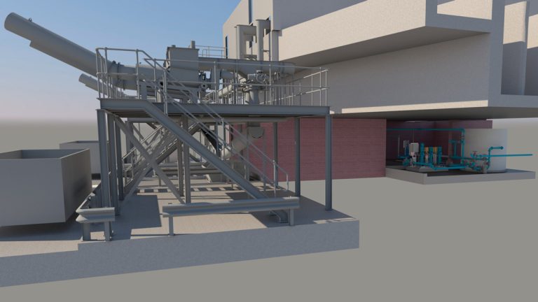
Civil 3D model showing inlet works modifications – Courtesy of MMB
Storm tanks
The solution called for a dual compartment storm tank with a total storm water storage of 51,000m3. The tank is 155m long by 80m wide, with a maximum depth of 6.6m. After consideration of several alternatives, MMB agreed with UU that the storm tank would feature:
- A single fill and draw pipeline.
- Precast concrete piles.
- An in situ concrete base sloping at 1 in 200 down to a collection channel and sump.
- Precast concrete walls (Sealwall units supplied by Naylor Concrete).
- A gated flushing system supplied by Jacopa.
The detailed structural design of the storm tanks was carried out by GHD who was appointed as subcontractor to MMB. GHD designed the in situ concrete elements, including the piled base slab, internal dividing wall between two compartments, flushing reservoirs and the interface with the PCC wall units. The design ensured a Class 1 watertight interface between the precast units and the in situ base.
The storm tank incorporates an innovative self-cleaning mechanism which involves holding water back in the end flushing reservoirs when draining down the storage tank. A series of gates are then released, flushing the channels of the tank. This system reduces whole life costs by significantly reducing the energy associated with traditional re-suspension pump systems.
The structure is supported on 1557 (No.) precast concrete piles driven to a depth of 20m below ground level. There is a perimeter pile cap supporting the PCC walls and a 400mm thick RC concrete base slab. The two compartments are divided by a 600mm thick in situ concrete wall.
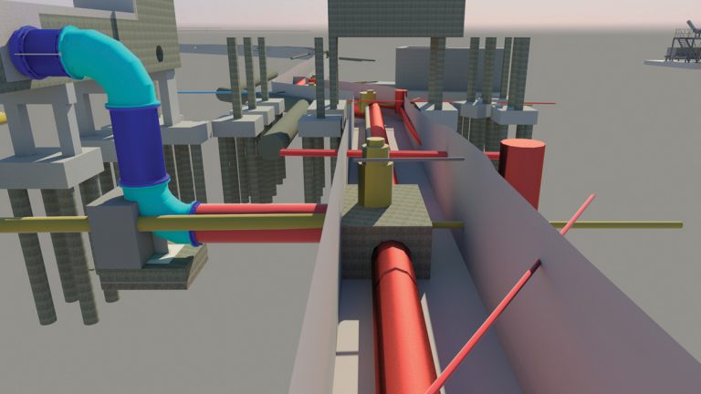
Civil 3D model showing the connection between the storm return pipework and the existing structure – Courtesy of MMB
A design for manufacture and assembly (DfMA) approach was adopted in order to deliver the scheme as efficiently as possible in terms of time, cost, quality and safety. The use of PCC wall panels reduced the risks associated with fixing reinforcement, working at height, working with readymix concrete and also reduced the number of workforce required on site.
The external walls are formed of a system of modular precast Sealwall panels which are bolted together and temporarily propped prior to casting them into the in situ poured perimeter ring beam. The ring beam depth varied to increase the height of the wall and achieve the required fall on the base slab.
The wall panels are made water tight by a combination of surface sealant and hydrophilic strips at the bolted joint locations.
Cross-site pipework
A 530m long pipeline was required to transfer screened and de-gritted storm water from the inlet works to the new storm tanks during storm events. When the new storm tanks reach capacity, this pipeline provides 800m3 of additional storage, before the existing storm tanks begin to fill.
Once storm flows cease, the same pipeline transfers this storm water to the existing storm return pumping station.
The installed pipeline is made up of 1400mm (450m) and 1200mm (80m) diameter glass reinforced plastic (GRP) pipe. Choosing a GRP pipe solution provided a significant materials cost saving, when compared to the alternative ductile iron option.
However, the adoption of the GRP solution resulted in a more technically involved installation for the site team. The increased buoyancy of GRP coupled with a high-water table made it necessary to negate flotation. The solution that was adopted utilised a geogrid geotextile as part of the backfilling detail. The geotextile is designed to mobilise additional soil loadings to counteract the flotation force.
Surplus excavated material from the pipeline route remained on site, used to landscape around the new storm tanks and associated new access roads.
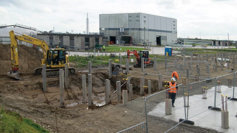
Excavation for pilecap following installation of piles – Courtesy of MMB
A joint locking system was adopted adjacent to the pipe bends which ensured that few thrust blocks were required; this proved advantageous on a spatially constrained and service congested site. The integrity of the pipeline was proved by pressure testing to 1.5 bar once backfilling ceased.
The new pipeline needed to connect to the existing reinforced concrete elevated storm channel and the existing 900mm diameter steel storm return pipeline.
A steel swan neck fabrication was utilised to overcome the abrupt change in elevation necessary to connect to the existing storm channel. To form this connection, the existing concrete channel structure required a point of entry as well and an RC soffit to the existing open channel to prevent hydraulic overtopping during operation.
Additionally, the channel at this point, required permanently isolating to prevent storm water from reaching the decommissioned 1930s storm tanks. The arrangement and elevation of the existing structure made this feature of the pipeline a challenging build.
Careful planning ensured the extensive formwork and access falsework, was in place in good time to adhere to the programme of works.
‘Hot’ (live) tapping was adopted for the connection to the existing storm return pipeline which needed to remain live during the works. The detail at the connection included a 900mm diameter steel gate valve and a 45° bend.
This connection was housed on a concrete base more than 4m below ground level. The construction of this installation was further complicated by working within a cofferdam arrangement of limited area that required regular dewatering.
Preston Storm Tanks Project: Key Project Participants
- Principal Contractor: MMB
- Principal designer: MMB
- Structural Design of storm tanks: GHD
- Geotechnical investigation: Geotechnics Ltd
- Precast concrete piling to storm tank: Aarsleff Ground Engineering
- Storm tank FRC construction: Stam Construction Ltd
- Inlet screen launder channels & washwater drum screen: Longwood Engineering
- Storm tank flushing gate system: Jacopa
- Primary settlement tank electrical installation: Bilfinger SE
- Inlet works electrical installation & storm tank flushing gate systems integration software: Boultings Ltd
- Inlet works mechanical and electrical installation works: Franklyn Yates Engineering
- Storm tank penstocks and actuators: Glenfield Invicta
- Primary settlement tank scraper bridge refurbishment & inlet screens washwater pipework: Integrated Water Services
- Supply of inlet screen washwater booster pumps: Northern Pump Supplies
- PST inlet penstock actuators: Rotork
- Primary settlement tank automation & storm tank systems integration software: Tata Consultancy Services
- Inlet works systems integration software: Adsyst Automation
- Flow to works measurement: RS Hydro
- Supply of precast concrete wall units: Naylor
- Readymix concrete supply: Cemex
- Supply of GRP pipework: Amiantit
- Supply of GRP pipework: Amiblu Norway AS
Inlet works improvements
To improve the performance of the inlet works the following interventions have been carried out:
- Replacement launder channels.
- Dedicated launder pumps.
- Automated launder stone traps.
- High speed actuators to the screen inlet penstocks.
- New inlet screen washwater system.
- Filtrate pumping station upgrade.
- Replacement laser type flow to works flow measurement.
The two existing launder channels connecting the four existing escalator screens to the 4 (No.) existing washpactors in duty/standby pairs, have been replaced with four dedicated launders. This, along with ancillary instrumentation and equipment and a re-write of the PLC, HMI and SCADA control software, has simplified the control and operation of the inlet works by dedicating each washpactor to its corresponding screen.
The replacement of the existing screen inlet penstock actuators with four high speed actuators, along with some additional control interlocks with the upstream terminal pumping stations, has enabled the inlet works to respond better to the large fluctuation of incoming flow rates.
The existing washwater pumping set has been replaced with a new system comprising of a 3mm 2D drum screen, a 500-micron Bollfilter and a variable speed booster pump set.
Due to the increase in launder flows, the existing filtrate pumping station has been upsized, including an increase of the wet well capacity, increased capacity duty/standby pumps and associated ancillary instrumentation and equipment.
Replacement launder channels – Courtesy of MMB
Conclusion
Whilst delivering a challenging and complex project, MMB and their subcontractors have worked over 250,000 hours without a RIDDOR reportable incident. By driving for innovation and adoption of a highly collaborative approach, MMB and UU have realised significant CAPEX savings whilst delivering a scheme that meets the Environment Agency commitments and delivering operational improvements.
The project has now been successfully handed over to United Utilities Operations staff.