
Queen Elizabeth II Reservoir (2022)
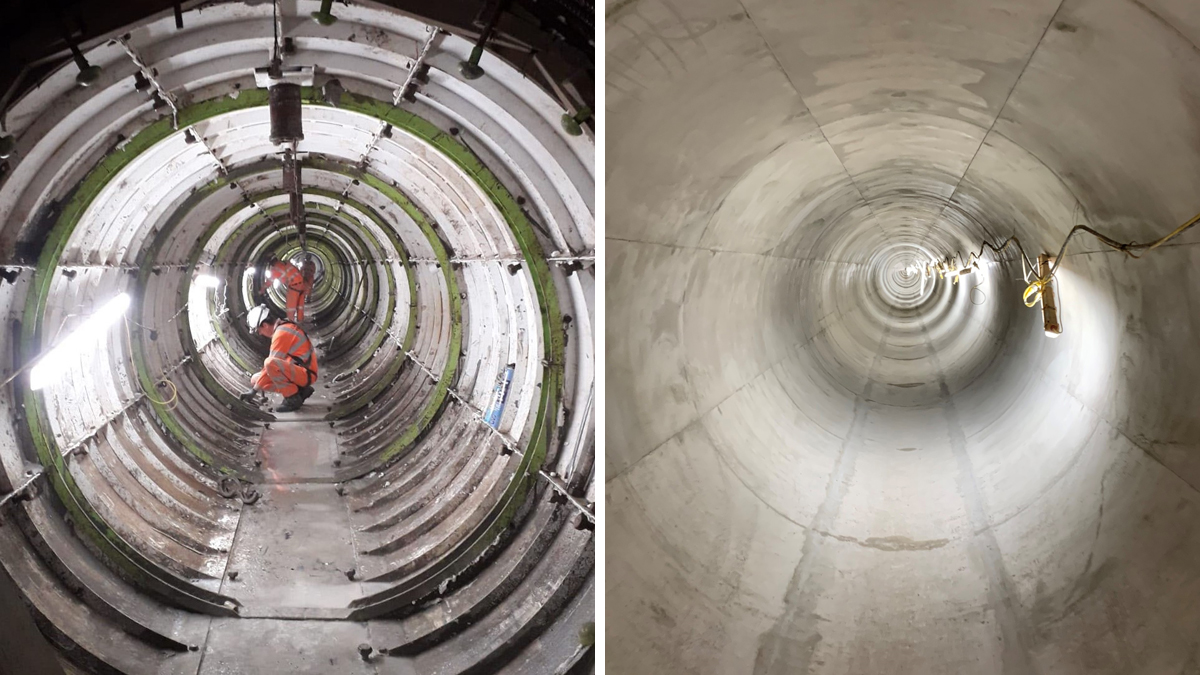
(left) Concrete relining underway and (right) relined tunnel - Courtesy of Barhale & Thames Water
The Queen Elizabeth II (QEII) Reservoir is a raw water reservoir in South West London that is owned and operated by Thames Water. The reservoir holds over 19 million litres of water, equating to 10% of the raw water storage for London. Once treated, this provides clean potable drinking water for millions of people across Surrey and London. Barhale was engaged by Thames Water as principal designer and principal contractor to complete the £11m tunnel relining contract to guarantee the integrity of the inlet and outlet transfer tunnels. The goal of the project was to increase resilience by strengthening the Wedgeblock tunnels.
Project scope
The main scope of the project involved relining two tunnels, each with an internal diameter of 2.54m. Maintaining this significant asset is an important measure in the enhancement of the supply network’s resilience.
Programme implementation
From the outset, a strategic outage plan by Thames Water was developed, implemented, and monitored. This was in keeping with the temporary and permanent design specifications, design risk and sequencing of construction; all of which would maintain the integrity of the Queen Elizabeth II Reservoir and the quality of the water.
Successful completion on time was essential to enable Thames Water to refill the reservoir during the winter months, ready for summer demands.
The programme was implemented in keeping with other works on the network, and the management of the pre-scheduled isolation programme on this project set a new benchmark for success. A highly collaborative approach between Thames Water, Barhale, other partners and stakeholders enabled the project to complete 6-months ahead of schedule and 7% under the contract budget. Making the most of winter flows to recharge the reservoir and reducing abstraction elsewhere from the River Thames, enabled 10% of London’s potable water supply to be reinstated early.
Queen Elizabeth II Reservoir – Courtesy of Barhale & Thames Water
Reservoir drawdown
Before the repair works could commence, the reservoir needed to be drained down in a planned and controlled approach, at optimum timing to ensure that all the water was transferred into the supply network and used for customer supplies. Starting in April 2021, the water level was reduced by 11m, leaving 6m of water in place to sustain the aquatic wildlife in and around the water.
Inlet and outlet tunnels
The inlet tunnel is 1060m in length and the outlet tunnel is 826m in length. Both were constructed in the early 1960s using an unbolted Wedgeblock technique that is reliant on the surrounding overburden pressures to keep the hoop structurally integral – keeping the tunnel intact. The tunnels are 40m to the mid-axis below ground.
To access and reline the tunnels, both the inlet and outlet required two access points.
For the inlet tunnel at Walton WTW, a surge tower pipe was removed for access and subsequently refurbished before reinstalling on completion of the tunnel lining. At this location, additional works included adding a 600mm butterfly valve to future-proof the surge tower to aid maintenance. The secondary access point for the inlet tunnel was a temporary 6m internal diameter access shaft constructed at the north-west boundary of the reservoir, constructed to an invert of approximately 44m below ground.
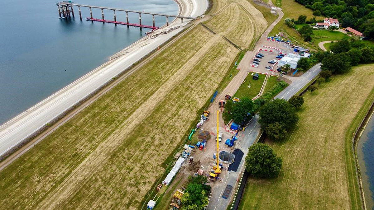
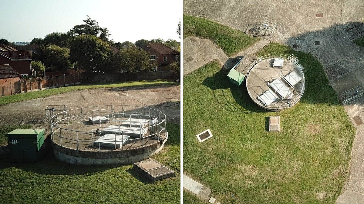
Aerial view of the reservoir and temporary shaft over the inlet tunnel – Courtesy of Barhale & Thames Water
The access points for the outlet tunnel were at an existing permanent shaft at Boormans Field site in a nearby residential area and at a new 6m diameter temporary access shaft constructed within the boundaries of the reservoir near the north-east entrance. The metrics of the shaft design were similar to the inlet.
To protect its workforce while relining the tunnels, Barhale worked collaboratively with Thames Water to complete and implement the robust and thorough isolation procedure. This included making sure that every valve and outfall into the tunnels was physically double-isolated as well as being electrically isolated to prevent all local and remote controls.
In total there were over 30 isolation points, which included a number of large valves within the reservoir. Specialist divers, DiveCo Marine Ltd, worked with the Barhale team to install blanking plates to provide the secondary isolation to each valve. These plates were 3.5m diameter and weighed 2.3 tonnes each, so required careful fitting and placement to guarantee full isolation.
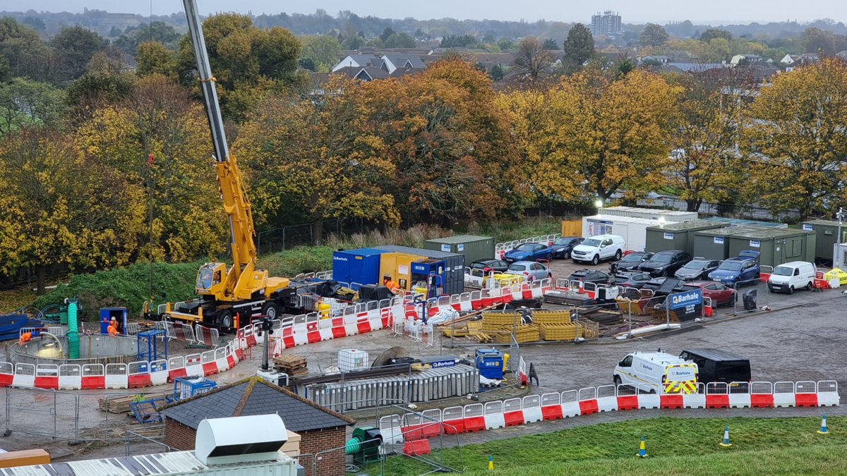
View of the outlet tunnel works area – Courtesy of Barhale & Thames Water
The temporary access shafts were constructed through a combination of caisson and underpin techniques. Both shafts were sunk to a depth of around 18m, using a 40t excavator with a telescopic pole grab and clamshell bucket. The team then changed to under-pinning, using a 3t excavator at the base of the shaft to excavate to formation level, encompassing the existing tunnels.
Reinforcing ribs were installed inside the tunnels to ensure their structural integrity was maintained during the shaft construction. Once the crowns of the tunnels were reached, the existing Wedgeblocks were carefully removed to facilitate the lining works. Each shaft progressed to around 2m below the invert of the tunnels, with a final depth of 44m.
The temporary shaft required for the inlet tunnel was located at the base of the QEII Reservoir embankment. This access shaft was between the reservoir embankment and Walton Road, which runs parallel to the northern side of the reservoir and is a well-used route between residential areas. To gain access safely and at the correct location over the tunnel, it was necessary for the shaft to encroach on the road. Initially it was essential that the road was closed, but as soon as it was safe to do so, one side of the road was reopened to minimise disruption to the travelling public.
A monitoring regime was discharged to data collect any ground movement and if the movement exceeded the higher trigger points, then the contingency plan would have been implemented. The monitoring was in place prior to construction to set a baseline trend and remained in place a month after final reinstatement of the works.
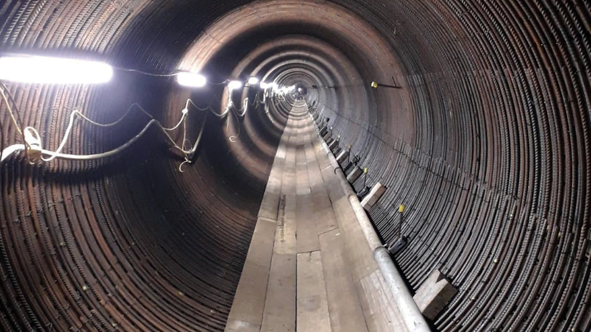
Tunnel in the process of being relined with the rebar installed – Courtesy of Barhale & Thames Water
Queen Elizabeth II Reservoir: Supply chain – key participants
- Client: Thames Water
- Main contractor & designer: Barhale
- Underwater surveys & secondary isolations: DiveCo Marine
- Resurfacing: Elm Surfacing Ltd
- Tunnel cleaning: Industrial Water Jetting Systems (IWJS)
- Steel fixing: KYN Services Ltd
- Lining shutter design: M3 Global – Kern Tunneltechnik SA
- Designer: Mott MacDonald
- Asbestos removal & demolition: Squibb Group
- Concrete supplier: Tarmac
- Steel: Devoran Metals
- Precast segments: FP McCann
Tunnel lining
To create the new 150mm thick liner, reinforcing radial and longitudinal bars were lowered through the shaft/tunnel interface and manually handled into place. The lining shutter design was undertaken by M3 Global – Kern Tunneltechnik SA. Once fixed in place, the shutter pans were installed in situ by the team, with concrete poured and cast in place. The team were working at a rate of 39m of tunnel concreted per day, allowing the night shift to strike the shutters, clean, remove and prepare the site ready for the commencement for the day shift to repeat the process.
The concrete was pumped down the shaft and along the tunnel, into the crown of each shutter section. The maximum distance of pour from the pump was 560m, utilising a 4” pipeline. Due to the distance to pump, the above ground and ambient temperature in the tunnels, the concrete mix was changed through analysis to ensure fluidity and workability were optimum, whilst not compromising the strength, finish or curing time.
All aspects of permanent design calculations were checked with an independent Category 3 consultant managed via Barhale’s designers Mott MacDonald. Once shaft construction at the inlet tunnel was complete, the team commenced work to the outlet tunnel temporary shaft which was within the grounds of the reservoir. At the location of the outlet shaft, an existing disused sampling building was demolished in advance to enable works to progress.
Outlet discharge at Boormans Field – Courtesy of Barhale & Thames Water
While relining works were underway on the inlet tunnel, the outlet tunnel was cleaned to enable relining to progress. This involved the removal of silt and zebra mussels which had settled along the tunnel walls and invert. This was carried out manually by Industrial Water Jetting Systems (IWJS) using scrapers and tunnel trollies which were then emptied at the tunnel access points using a vacuum system. Once cleaned, and with the isolations in place, a similar process was applied to the outlet tunnel. The benefit of utilising the same team across both tunnels increased productivity and reduced risk, whilst maintaining exemplary health and safety standards. In doing so, the commissioning of the entire site wide works was completed in an efficient process, allowing swift project closure.
Conclusion
Barhale implemented efficiency levers to improve the outline construction programme and worked in collaboration with Thames Water, resulting in completion 6 months ahead of schedule.
This was a significant efficiency saving for Thames Water, allowing the reservoir refilling operations to commence in November prior to the Winter flows in the River Thames, which significantly reducing the refill duration and maximised the stored water ahead of summer demands. Given the exceptionally hot and dry summer, the early completion and maximised storage has been more important than ever this year.