
Salford Priors S101a – First Time Sewerage Scheme (2017)
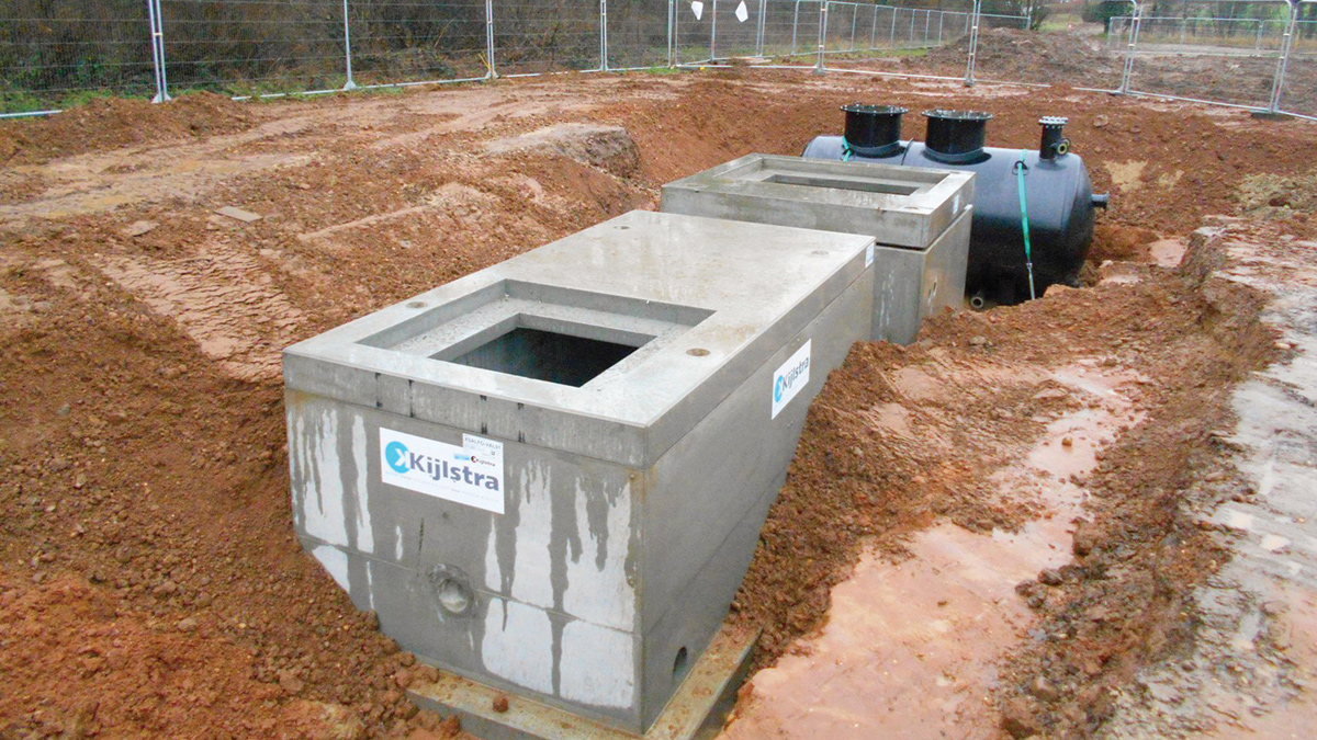
Valve chamber, SPS and vacuum tank - Courtesy of Severn Trent Water
An application for first time sewerage has been made under Section 101A of the Water Industry Act 1991. The application requests Severn Trent Water (STW) provide access to a public sewer for 28 duty (polluting) properties in the Iron Cross, Rushford and Pitchill settlements in the area to the west of Salford Priors, Warwickshire. An additional 29 non-duty properties have also been planned to be enabled in the course of the scheme. The main basis of the request for a public sewer is that private septic tanks or small treatment works discharging to individual soakaways do not work satisfactorily. Moreover, the soakaways are affected by the seasonal high water table or unsuitable ground conditions, which leads to pollution/environmental issues. This scheme contributes to STW Business Plan objective ‘We will safely take your wastewater away’, as well as to help fulfil their regulatory obligation to deliver 312 duty properties during the AMP6 period.
Solution
Under the AMP6 framework agreement, NMCNomenca (now Galliford Try) was appointed as the main design and build contractor and worked closely with STW from the feasibility stage of the project.
Using a conventional solution, 4 (No.) sewage pumping stations (SPS) would have been required due to the area’s undulating topography, leading to deep gravity sewers, thereby increasing the construction programme and cost. Additionally, full road closures would have been required, causing long term disruption to the local residents with an official diversion route of 20km (which the Highway Authority objected to during discussions in Stage 1). It is also likely that the extended programme and disruption caused by the road closure would have resulted in a significant increase in business compensation, particularly from the quarry and the industrial park to the north of the area. One further complication is that the location of one of the pumping stations would have clashed with the proposed access for a scheduled mineral extraction promoted by Warwickshire County Council.
Because of these significant disadvantages of a conventional system in this application, the chosen solution was a vacuum sewage system which included 3km of vacuum main with just one centralised vacuum and pump station, 750m of pumped rising main and 640m of gravity sewer.
The effluent discharges at a rate of 5l/s into the nearby wastewater sewer network in Salford Priors catchment. This solution eliminated the need for 4 (No.) SPSs which has a significant saving in OPEX costs, allowed the work to be carried out under traffic lights to minimise disruption and reduced the associated land & planning complications.
NMCM appointed specialist vacuum subcontractor CG Godfrey Ltd to undertake the work on a full design and build framework.
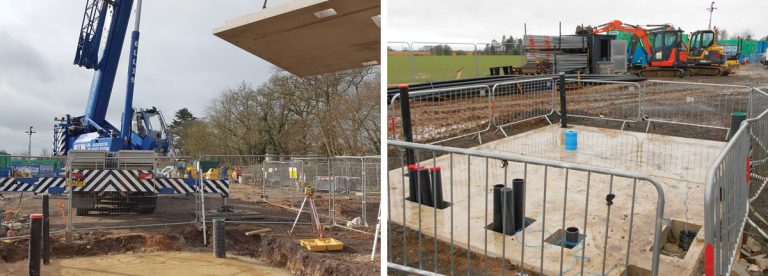
(left) Installation of precast concrete kiosk base – Courtesy of NMCNomenca and (right) Precast concrete kiosk base – Courtesy of Severn Trent Water
The vacuum network
All the properties within the application will be enabled using Vacuflow® Vacuum Sewer Systems, (Vacuflow systems), apart from three properties along School Road, which will be serviced by a gravity lateral connection from the gravity sewer system. Each property, or in some cases a group of houses, has a vacuum chamber or ‘pot’, which collects their sewage via a new gravity pipe immediately upstream of their existing septic tank/cess pit.
These pots are a similar size to a standard manhole and are preferably located in the highway verge or, where this is not feasible, within the customer’s property boundary.
Vacuflow systems are a mechanised method of wastewater conveyance that utilises differential air pressure to convey wastewater i.e. atmospheric pressure in the collection chambers and negative pressures (reaching -0.8 bar) within the infrastructure pipework.
Each collection chamber requires an interface valve to seal the vacuum lines and maintain internal negative pressure. The interface valves work pneumatically: once wastewater within the chamber reaches a predetermined level, the operation of the valve is triggered by a starter valve switch mechanism positioned on top of a ball float. When the interface valve is open, the resulting differential pressure drives the wastewater in the collection chamber towards the central vacuum station. The starter valve will remain open until the ball float trigger switch has dropped back down. No electrical installations are required within the collection chamber, creating a low-maintenance solution.
The vacuum network is laid to a ‘saw tooth’ profile, whose ‘lift pockets’ are used to effectively form a plug in the pipeline network, overcome obstacles, transport wastewater uphill and ensure shallow pipework where possible.
The vacuum station is the only element within the Vacuflow system requiring electrical supply, whose vacuum pumps run for approximately 2 to 5 minutes per cycle (just long enough to create sufficient negative vacuum).
Once the wastewater reaches the vacuum station, it is deposited into the vacuum tank where it is temporarily stored until the tank fills to a predetermined level. Once this level is reached, the system’s discharge pumps are activated and the wastewater is conveyed through a pumped rising main and then a gravity sewer to the nearby sewer network.
Innovation
A number of efficiencies have been made to meet a tight construction programme, in particular the emphasis on prefabrication. The use of prefabrication in construction offers the potential for a reduction in construction programme, improves health and safety because construction is undertaken in a controlled factory environment, reduces waste and ensures precision and efficiency.
Examples of the use of prefabrication in this project include the vacuum collection pots, control kiosk delivered to site fully fitted and wired with pumps and MCC, kiosk base slab, vacuum collection tank, valve chamber and pump station.
All off-site manufacture components were consecutively programmed for delivery to ensure only one crane visit was required, and the vacuum pumps are fitted with retractable wheels, which eliminates the requirement for manual handling.
Hermelock’s composite manhole covers have been used in both the highway verge and on private property. They are constructed from polyurethane and reinforced with fibreglass with matching frame made of reinforced polypropylene. Its major advantages include; being lightweight, having a bolting system, odour-proof sealing, resistance to chemical attack, non-conductive and water-tight properties, resisting loads according to the standards EN-124 class D-400 and having zero scrap value, thereby preventing theft.
They have been given a 25 year guarantee (subject to correct loading requirements and installation) and, providing they are successful, will be added to the approved products, having been approved by STW standards development.
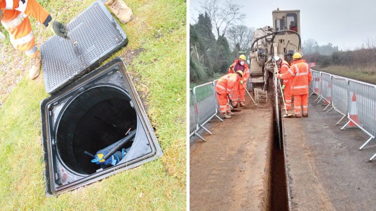
(left) Hermelock composite cover – Courtesy of Severn Trent Water and (right) Narrow trench created by trencher machine – Courtesy of NMCNomenca
The vacuum mains have been installed using a road trencher, where possible, to excavate narrow trenches to the required depth to reduce the extent of highway reinstatement. It is a rapid method of excavating within the road, typically achieving between 150 and 200m per day. All the pipe-laying and telemetry is carried out from the surface, eliminating the need to enter the trench. Foamed concrete, which is used to backfill the trench, has several advantages:
- Its air content (between 50% and 75% by volume) makes it a very lightweight and free-flowing material. It is therefore easy to place, pour or pump to the required location.
- It is self-levelling, which eliminates the requirement for compaction/vibration.
- It is less likely to crush objects below it.
- It imposes less lateral loading.
- It is a sound and thermal insulator.
- It absorbs very little water, meaning it is resistant to freeze-thaw cycle that can cause spalling in traditional concrete, and offers reliable quality control because each batch can be quickly and easily reproduced.
- It is easy to re-excavate if necessary.
- It is naturally resistant to fire.
- It is a non-hazardous material, both during the application and once it is set in place.
Building for the future
At the time of writing (June 2017), approximately 70% of the enabled properties have taken STW up on the offer of connection; however, in circumstances where the customer has decided that they do not want to connect, provisions have been put in place to allow for a future connection.
Each collection pot includes a sensor that feeds back to the vacuum station such that, if a blockage occurs, the station’s control panel will inform STW SD and identify which pot is affected.
Where the collection pots are located within the customer’s land, an isolation valve is positioned at the boundary to enable the operator to shutoff the pot if access cannot be taken at the time. Each pot has enough storage for approximately two days of flow, which is considered sufficient to allow SD to attend the property and resolve any problems. Otherwise, the collection pots only require an annual cleanse using a Jet-vac tanker.
Customer involvement
A scheme of this nature clearly warrants thorough customer engagement. In addition to the letter drops at a number of milestones in the project, members of the design team met with each resident to discuss their current drainage arrangement and agreed the preferred location for their collection pot (where the verge was not an option).
Furthermore, a well-attended two-day public exhibition was held at the village hall, which gave local residents the opportunity to find out more about the scheme, how it may impact them and provided another opportunity to confirm their private drainage arrangements.
During construction, the site team maintained pedestrian and vehicular access to the customers’ properties, typically by the use of road plates. In a small number of cases, where the circumstances and construction method did not allow this, customers were contacted several days in advance to allow them to make alternative short-term parking arrangements.
As a result of the site team’s continuous commitment to excellent customer engagement, numerous positive feedback forms have been received.
Progress
Construction began on site in September 2016 and progress is such that, following commissioning and training, completion within the agreed time-frame, cost and quality is anticipated in July 2017. The project team has achieved highly in all design, construction and environmental audits to date (both internal and external), which resulted in the receipt of an Integrated Assurance Award from STW’s Project Delivery Assurance team. In addition, there have been no major H&S or environmental incidents.