Bynea Sewage Pumping Station (2017)
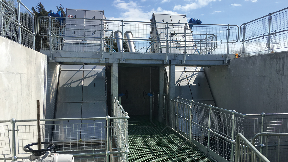
View of escalator screens installed within screens chamber - Courtesy of Arup
Dŵr Cymru Welsh Water (DCWW) is carrying out a strategic package of works in the Llanelli and Gowerton catchments with the aim of reducing spills into the Loughor Estuary. Bynea Sewage Pumping Station (SPS) is a key asset, receiving sewage flows from the local catchment and transferring them to Llanelli WwTW. The site originally operated as a sewage treatment works but in 1995 was converted to a sewage pumping station. The pumping station was upgraded in 2003 by adding storm pumping and storm storage capacity.
Background
Bynea Sewage Pumping Station serves an upstream catchment with a population equivalent of 19,698. Combined flows from the catchment are transferred via gravity sewers and are received at the pumping station wet well. Flows up to the pass forward flow (PFF) of 501l/s are pumped to Llanelli WwTW for treatment. The foul pumps discharge into a 700mm diameter rising main that is 1,700m in length and discharges to the inlet works at Llanelli WwTW.
Flows in excess of the PFF are pumped to the circular storm storage tanks on site. Excess storm flows spill over a high level weir around the edge of each tank. There are two overflow pipes, the use of which depends upon tide conditions.
The primary discharge is down the sea outfall to the Loughor Estuary; however, when the outfall is tide-locked, then the overflow is to an unnamed tidal pill. Return storm flows are pumped back to the wet well.
During AMP5 Welsh Water carried out a project to resolve sewer flooding in the upstream catchment by increasing the capacity of the sewer network. A performance assessment of Bynea SPS was carried out to identify any risks at the pumping station that could impact on the flooding upstream.
The assessment determined a number of issues:
- Foul pumps not achieving the required PFF, unreliable and failing repeatedly; primarily due to blockages.
- Large amounts of solids settling out within the rising main, reducing its capacity and increasing the pumping head.
- Rising main air valves inaccessible for maintenance.
- No storm pump standby capacity and the storm pump rising main inadequately sized.
- Manual intervention is required to empty the storm tanks.
- Inadequate screening of overflow discharges and screen prone to blinding.
- Capacity of the mains power supply reached and exceeded on occasions.
- Standby generator inadequately sized to run all duty pumps.
It was determined that the pumping station and rising main would be dealt with under separate projects. The scope of this paper covers only the pumping station project.
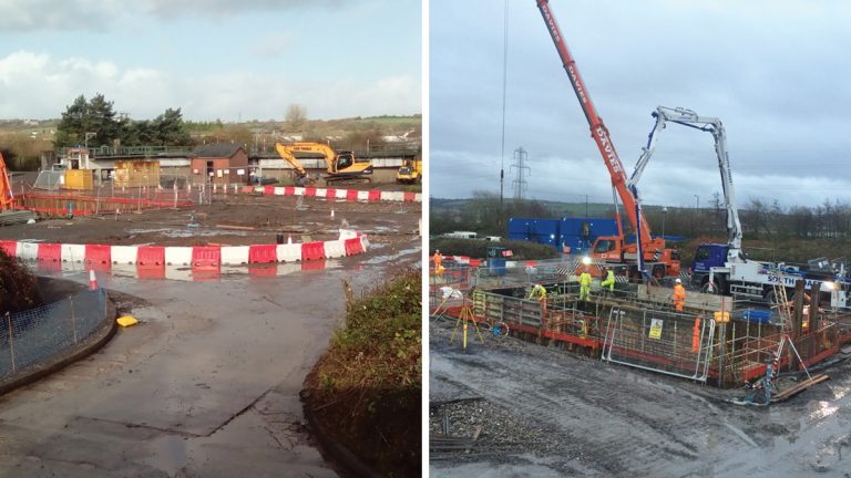
(left) View of construction works – Courtesy of Arup and (right) overall working area – Courtesy of Morgan Sindall
Design
The key drivers for the design were meeting consent requirements and reducing the risk of flooding in the upstream catchment.
Hydraulic modelling of the sewer network was used to determine the flows received at the pumping station. The peak inlet flow is 850l/s, therefore given a PFF of 501l/s, excess storm flows of up to 350l/s are anticipated.
The existing pumping station included a grit trap that was not maintained and had become disused. The design reinstated this grit trap, preventing solids being carried forward and reducing deposition in the rising main. The design also caters for screening of all incoming flows at the pumping station. This provides benefit by reducing the risk of pump blockages and removal of rags from flows passed forward to Llanelli WwTW.
The hydraulic design considered the need to avoid surcharging of the upstream incoming gravity sewers and hence influenced the depths of the new screens chamber and pumping station shaft (approximately 6m and 8m deep). The new inlet screens and screen channels were designed to operate over a wide flow range, from 50l/s to 850l/s.
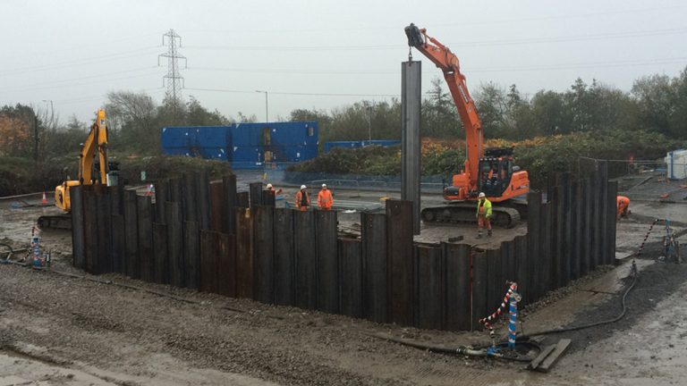
Installation of sheet piles for screens chamber excavation – Courtesy of Morgan Sindall
The water retaining screens chamber was designed as an in situ reinforced concrete structure. The design uses thicker walls with less reinforcement, which saved construction time and cost. The chamber is designed so that in dry weather it can be temporarily isolated from incoming flows and then ‘free-drained’ into the new pumping station structure, to avoid the requirement for pumping out prior to access for maintenance.
The pumping station wet well was designed to incorporate both foul and storm pumpsets. The wet well was physically scale-modelled to optimise the hydraulic design, which enabled a smaller diameter shaft. The pumping station shaft structure design to account for flotation takes benefit from the jacking collar, skin friction and significant volumes of benching to reduce the overall volume of concrete used.
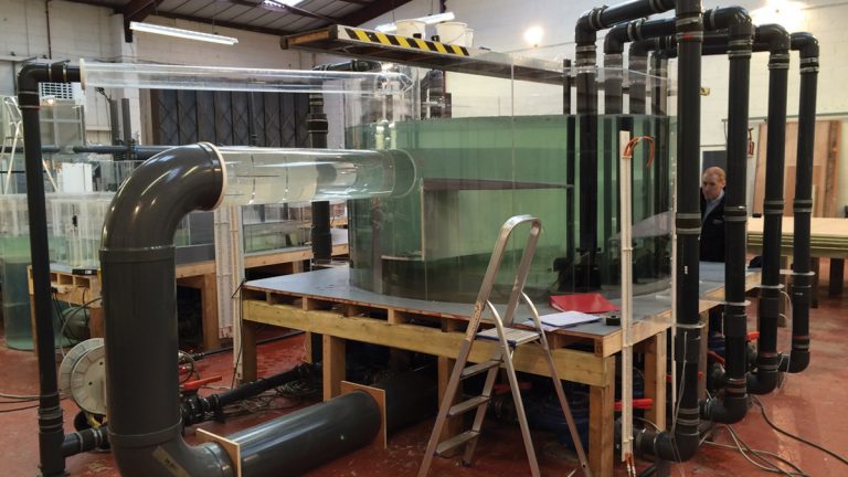
Physical scale model of pumping station – Courtesy of Arup
Welsh Water and the pump supplier were closely involved to develop a design with good access to all maintainable components. Access arrangements over the pumps and wet well avoid the need for operators to remove floor covers or work over unprotected openings. Fixed walkways and landings with handrailing were incorporated along with stairway access to assist with pump removals, while valves were located above ground to remove the need for confined space entry.
The position of both the new screens chamber and pumping station shaft allowed them to be constructed and then partially-commissioned off-line, prior to connection to the existing incoming gravity sewer, avoiding the need for significant temporary overpumping.
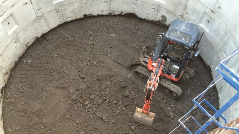
Construction ongoing within pumping station shaft caisson – Courtesy of Morgan Sindall
A 600mm diameter ductile iron pipe connects the new foul pumps to the existing rising main. The connection point is to a ductile iron section of the rising main upstream of the transition to GRP pipework, to avoid the difficulties associated with connecting dissimilar materials.
The existing storm storage tanks were modified to allow them to be drained by gravity, cutting the costs associated with the old pumped return system. The new rising main pipework feeding the storm storage tanks was designed for off-line installation, enabling the storm tanks to be kept in service throughout the construction phase.
The controls for the new equipment are contained within a motor control centre (MCC) located in the existing control building. The design enabled off-line installation so that testing and commissioning of the new equipment could be carried out while the existing pumping station remained operational. A touchscreen human machine interface (HMI) provides a local interface for the operators, while the programmable logic controller (PLC) is linked to Welsh Water’s telemetry system for remote monitoring and reporting of alarms. The control philosophy for the variable speed foul pumps incorporates features to minimise blockages whilst maintaining smooth pass forward flows. The existing storm MCC was retained for existing equipment that forms part of the new storm system, including storm tank cleaning pumps and instrumentation. The PLCs in the two MCCs communicate over an ethernet network.
An upgraded mains power supply was provided, with a new ground-mounted substation established outside of the site boundary. The existing standby generator was replaced with a new 500kVA containerised standby generator including an integral bulk fuel tank. The container design facilitated rapid installation and provides increased security.
Construction phase
The site is located down an access track of approximately 3m width, which is also part of a frequently used public right of way. Due to the scale of the structures and the need for large plant to access the works, it was decided that a separate access track would be constructed for construction vehicle movements and to safeguard pedestrians and cyclists in the area. Arrangements were made to provide site access through an adjacent car park via a purpose made 100m long track complete with segregation.
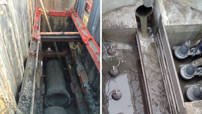
(left) 900mm concrete pipe being installed – Courtesy of Morgan Sindall and (right) Pumping station wet well during commissioning – Courtesy of Arup
The site’s water table is at approximately 1.8m below ground level. Given the excavations required for the 8.9m deep pumping station and the 6.1m deep screens chamber it was decided to install a dewatering system to enable the construction of the large structures. Seven deep well dewatering points and one observation point were installed to a depth of 10m around the main working area to encompass the zone of influence. The dewatering system was operational for 24 hours a day over a period of 16 weeks.
Civil works construction
The programme was developed to enable construction of the two large underground structures simultaneously in order to achieve the optimum output and limit the duration of the overpumping on site.
The 12m long, 5.9m wide screens chamber was constructed with in-situ reinforced concrete, while the excavation for the chamber was undertaken by installing a cofferdam allowing for working room.
The 9m deep, 7.5m diameter pumping station shaft was constructed via a top down caisson method. Six jacks bolted onto a jacking ring pushed the bolted concrete segments down as the earth within the caisson was excavated. A 1.4m mass concrete plug was poured at the formation level, which enabled the reinforced base and benching to be constructed.
Whilst working on the large concrete structures, the separate deep pipelines were installed to improve efficiency of the programme and completed whilst the dewatering system was in place.
The cable duct runs used precast drawpits, which were delivered to site and installed on the same day. The use of precast concrete enabled a cost saving of over two thirds compared to traditional plastic sections/brick work. Excavated material was utilised to create a screening bund. The screening bund provides effective visual and noise screening of the site from the public rights of way that run parallel. This 1,800m3 bund resulted in a saving of 95% of the waste sent to landfill.
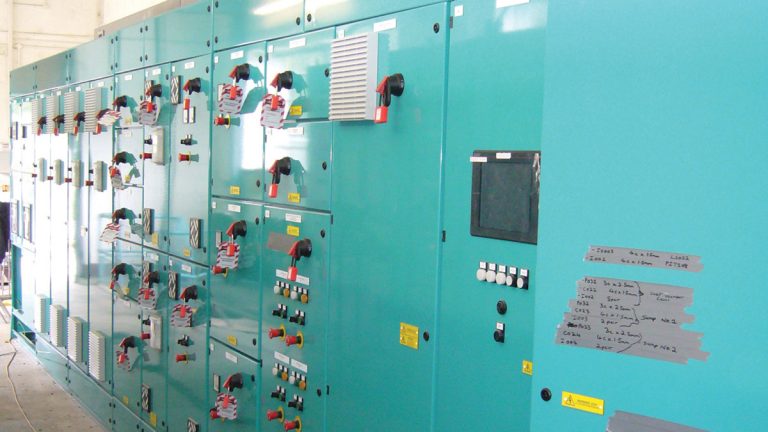
New MCC being installed – Courtesy of Arup
Mechanical and electrical installation
The pumping station shaft houses four foul pumps and three storm pumps as well as the riser pipework, handrailing, access bridge and pipe manifolds. As well as benching within the wet well, the more intricate flow vanes and baffle plates were fabricated from steel and fixed within the base of the wet well.
The existing MCC was fully operational whilst the new one was being installed and a phasing and commissioning plan was developed to ensure a smooth transition from the old system to the new operating system. As the new MCC and associated variable speed drives generate more heat, a new ventilation system was installed to mitigate the increased temperature.
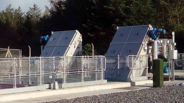
View of new inlet screens – Courtesy of Arup
Commissioning
Following completion of all construction works and once all the necessary equipment was dry commissioned, the final change over of flows and systems could begin. The first operation was to make a connection to the existing foul rising main, with minimal shutdown time due to the incoming flows. This involved draining down the existing rising main and overpumping to the storm tanks on site, which was undertaken during a sustained period of dry weather to minimise the incoming flows.
A shutdown of the electrical systems was undertaken with the backup generator running so the new mains power upgrade could be connected and the electrical apparatus transferred over to the new system.
Bynew PS – Supply chain – key participants
- Client: Dŵr Cymru Welsh Water
- Principal contractor: Morgan Sindall Construction & Infrastructure Ltd
- Designer: Arup
- Dewatering installation: WJ Groundwater Ltd
- Cofferdam designer: MGF Ltd
- Screens chamber: HOS Civils Ltd
- Pumping station shaft: HB Tunnelling Ltd
- Mechanical installation: Whitland Engineering Ltd
- Electrical installation: Zone Electrical Ltd
- Inlet screens & screenings handling: Huber Technology
- Motor control centre: General Panel Systems Ltd
- Standby generator: Power Electrics Generators Ltd
- Pumps: Xylem Water Solutions UK Ltd
View of pumping station – Courtesy of Arup
Conclusion
The project has achieved its aims by delivering improvements in pumping efficiency and reliability. The reinstated grit removal and new inlet screens will reduce future maintenance requirements at both Bynea SPS and Llanelli WwTW. The new pumps achieve the required PFF and in combination with improved control is resulting in less flow into the storm storage tanks, which will contribute to a reduction of spills into the Loughor Estuary.