
Hayle STW – Inlet Refurbishment Works (2018)
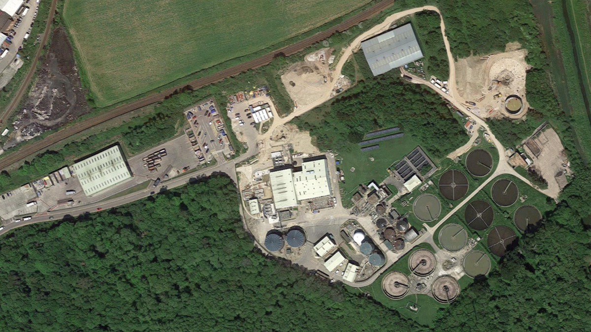
Hayle STW situated adjacent to the River Hayle - Courtesy of SWW Delivery Alliance H5O
Hayle STW is located at the end of the Hayle estuary in West Cornwall approximately 7 miles east of Penzance.The area immediately surrounding Hayle STW has a small population made up of St. Erth Village. The site itself is located within a large plot bordered to the north by the West Coast Main Line, and to the east by the River Hayle. The primary objectives of the project were the remediation of concrete corrosion within the existing inlet works chamber and launder channels, the provision of effective inlet screening and screenings handling from the 7 (No.) incoming pipelines that provide the 1800 l/s pre-storm separation to the inlet works, and the provision of covers over grit plant to allow appropriate and safe access.
Background
The wastewater treatment facility receives flows via 3 (No.) siphon mains and 4 (No.) pumping mains, 1 (No.) tanker import and 1 (No.) site drainage and liquor returns pumping main. These flows are received into a concrete reception chamber and delivered to the existing coarse screens, ‘detritors’ then fine screens via a series of RC channels circa 1.2m by 2m deep. Full flow to treatment is 795 l/s; however, the inlet works is pre-storm separation and so can receive 1800 l/s.
All elements of the existing inlet scheme are badly affected by the resulting attack due to the high levels of H2S. The upgraded treatment facilities at Hayle had to be designed to withstand the harsh environment, and various options were considered.
Summary of options
The process review considered seven different options which were categorised into two types:
- New off-line build.
- Refurbishment and adaption of the existing system.
The scope of the works
Refurbishment and adaption of existing system: This would require systematic shutdowns of sections of the existing inlet works to enable concrete repairs and changes to the channels to suit the new screens dimensions and hydraulics. This option would require a complete diversion of incoming flows to the reception chamber during its refurbishment, and the facility to use the numerous outdated valve, penstock and stop-log isolation assets plus the addition of new methods of further isolation to enable the work.
Critically, the option to refurbish the existing channels would require man access into confined space in close proximity to the live flows that have created H2S and subsequent decay to the concrete and screens.
The work would mean the existing building, which has suffered from historic H2S attack, would need to be brought up to current standards to suit the new system and provide a safe working environment for the client.
Due to the numerous and complex interfaces, and a lack of information, e.g. whether the new screens would have the required hydraulic conditions to enable them to perform, meant this option was too onerous to price and would have resulted in the client holding many financial and time costs risks.
New off-line build: This option meant the whole scheme could be built off-line, with little interface with the existing works; in fact only the nine incoming flows to the works, the one back end connection and odour control requirements would interface with the existing works.
With the project designer able to provide basic design of the flow paths, the screen suppliers were happy the hydraulics would be correct for their screens.
Proposal
From the seven options tabled, it was decided that Option 6, an off-line build, would be chosen to go forward for construction.
Screen and grit plant materials were to be suitable for saline environment, and the new channels/structures were to be PE lined, or similar corrosion resistant material. All interconnecting pipelines were also required to be MDPE or similar corrosion resistant material. Performance had to be in accordance with the relevant South West Water technical standards with exceptions: i.e. no stone trap in the reception chamber or reception chamber bypass; coarse screen to be 50mm bar spacing, and a sacrificial replaceable corrosion resistant liner will be applied to grit trap.
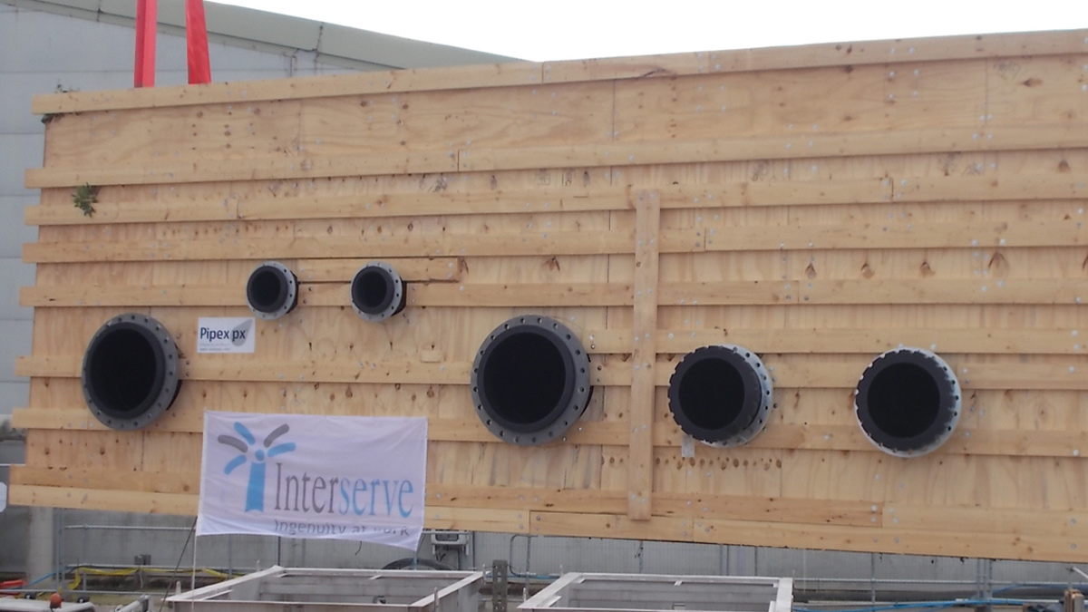
MDPE reception chamber being craned in – Courtesy of SWW Delivery Alliance H5O
Main MEICA assets
- Duty/standby coarse screens – rated at 110% of influent design flow (2035 l/s).
- Duty coarse screens screening handling unit.
- Duty grit trap – rated for 1850 l/s.
- 3 (No.) fine screens (duty/assist/standby). Each screen is rated for 70% of the design inflow (1295 l/s).
- Duty/standby screening handling units.
The provision of a failsafe hydraulic bypass to coarse and fine screens would also be allowed. All plant and channels had to be effectively enclosed and be connected to and ventilated via the existing odour control to reduce odour risk and minimise H2S concentrations. Visual screening of the new plant was required and where any existing plant and equipment were to be removed, openings to be made safe with new handrail. All options required repairs to the existing building which were scoped via a third-party quotation.
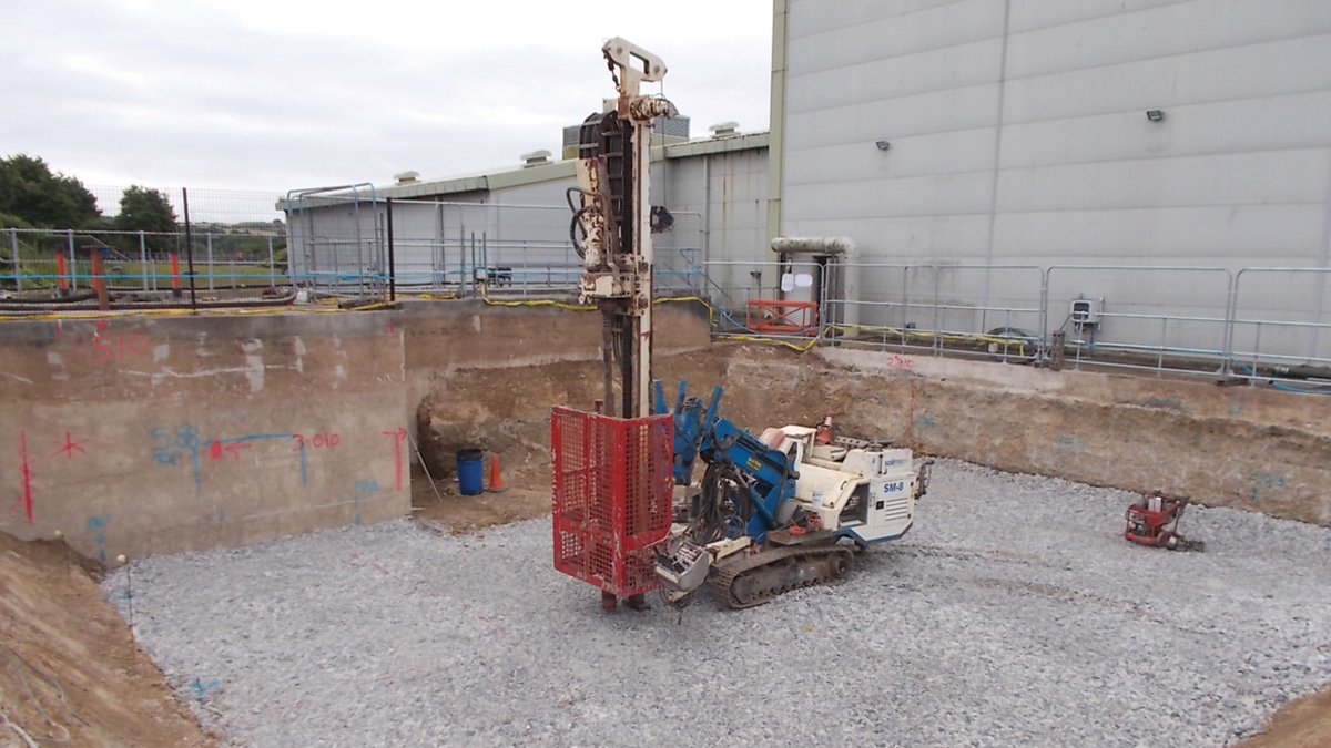
Reception chamber/coarse screen construction works – Courtesy of SWW Delivery Alliance H5O
Flow path
The chosen design diverted all the incoming flows into a new MDPE structure from Pipex px® containing 2 (No.) Rotork actuated IVL 1200mm wide-wall mounted penstocks, through 2 (No.) duty/standby Longwood Engineering 50mm coarse screens, with the provision of a bypass, and isolation at the rear of the screen provided by 2 (No.) MDPE 1200mm diameter gate valves from Althon Ltd.
The flows are carried through this area in Uponor 1200mm diameter MDPE pipes, some above-ground and some buried. The screenings collected by the 2 (ER) ER screens flow along Longwood launders to a Combi 400 Screenings handling unit.
The flow is next carried to the Tuke and Bell 6m diameter grit removal plant, complete with a dry well pumping station, and then piped between the grit plant and the fine screen reception chamber along a buried 1200mm diameter Weholite® pipe, which was internally welded.
The fine screen area consists of a Pipex reception chamber, complete with overflow weir and associated bypass pipework, and then into 3 (No.) 6mm duty/assist/standby Longwood fine screens, with the same isolation provision on the front and rear as the coarse screens.
Launders transport the screenings to 2 (No.) Longwood screening compactor units at a lower level.
Hayle STW Inlet Refurbishment Works: Table of designers, contractors and main suppliers
- Main contractor: Interserve
- Project designer: Arcadis
- Electrical installation: Bridges Electrical
- creen, launder, compactor and prefabricated tank: Longwood Engineering
- GRP fabrication – covers: GRPro Ltd
- MDPE reception chambers and 1200mm pipe: Pipex px Ltd
- Weholite® MDPE tank & pipe supplier: SDS Limited
- Groundworks and pipe installer: EA Grey
- Crane hire: Macsalvors
Construction
With the existing site continuing to operate during the new construction phase it was important to maintain small footprints within the site at key locations.
Diversion of 7 (No.) pipelines
- Start Pumping Main: A 600mm DI pipe from the catchment pumping station on the treatment plant land carries sewage from the PS to the reception chamber (flows were tankered during the connection).
- East Quay Main: A 600mm DI pipe from the catchment pumping station on the harbour wall in nearby Hayle, carries the sewage to the site and into the reception chamber (flows were tankered during the connection).
- St. Ives twin siphon mains: These transport the St Ives sewage via a balancing tank that was investigated and utilised by the site team as a location to divert/hold/tanker the flows during the connection works.
- Treloweth and the Creamery Pumping mains: These are two mains local to the site; their respective pumping stations are within a 2 mile radius and were easily tankered during connection.
- Crowlas siphon main: This carries the flows from Chyandour, Penzances’ pumping station, which has a shaft and tunnel storage attached, plus four other pumping station flows on its route to Hayle STW. This connection required a large excavation as the pipe is 700mm diameter DI and was within a trench 2m deep in the bedrock. The same valve and tee arrangement was used on all the connections.
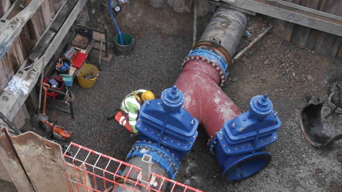
Crowlas syphon main connection within sheets and frames supported excavation – Courtesy of SWW Delivery Alliance H5O
Coarse screens construction
- Decommission and removal of the existing permanganate dosing unit including an RC base and piles, and the temporary relocation of a tanker import facility; the associated RC road was also removed.
- Trial holes and investigations to locate existing services, with subsequent Isolation/decommissioning of existing services.
- Relocation and replacement of existing fences (site security and tanker driver segregation fence).
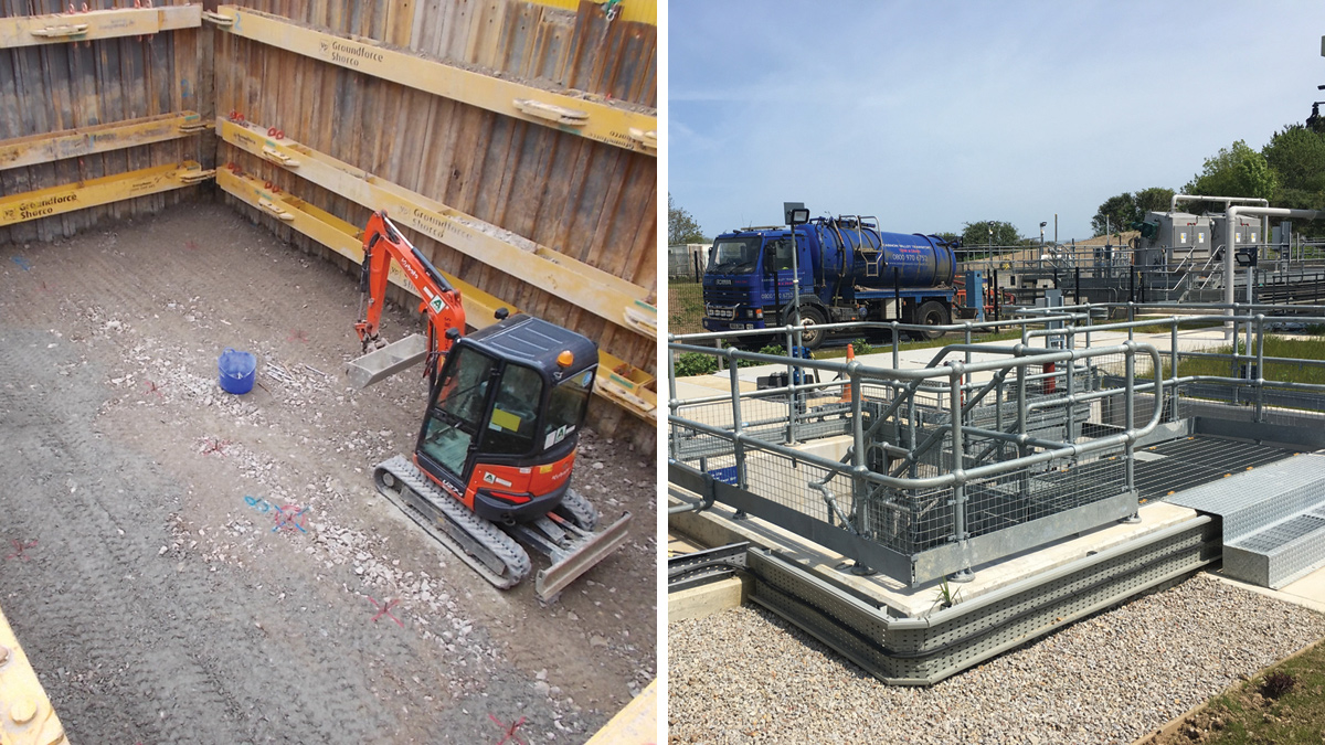
Excavation
- Battered excavation controlled by permits and quality forms to ensure compliance with the temporary works design.
- 2m further excavation to locate 700mm DI feed pipe before piling.
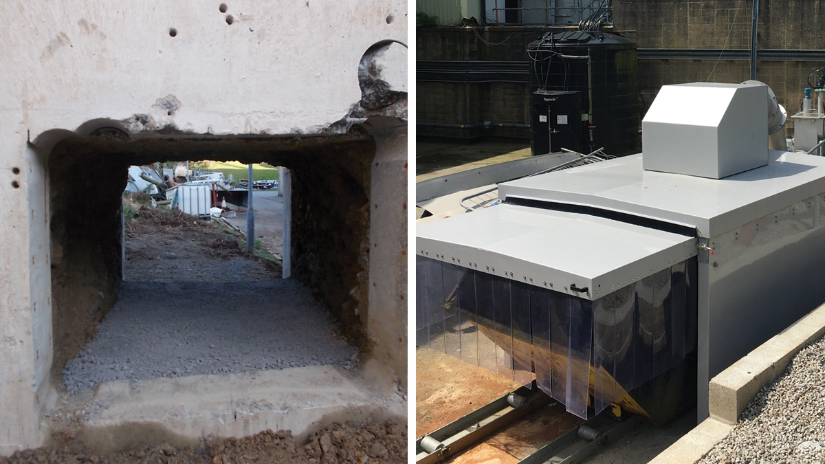
(left) Coarse screen area excavation through an existing structure and (right) Coarse screen screenings handling skip cover – Courtesy of SWW Delivery Alliance H5O
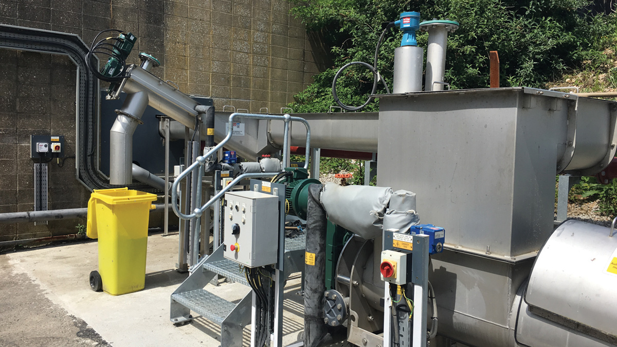
Coarse screen screenings handling area – Courtesy of SWW Delivery Alliance H5O
Civil and MEICA installation
- Preparation of a fully drained piling mat, piling consisted of 20 (No.) mini piles, capped and tied together with a 450mm thick, 20m x 14m RC slab.
- Installation of a prefabricated MDPE (Pipex) unit to form the new reception chamber and prefabricated stainless steel tanks to hold the new screens. Prefabricated GMS access walkways, stairs supports and handrails were installed.
The coarse screen, screenings handling unit was constructed on the other side of an existing 4m tall and 2.5m wide RC structure which the launder channel had to pass through. The 300mm thick walls that were on either side of the structure required ‘stitch’ drilling into an earth filled void below the main Inlet channel from the existing works. This same method had to be adopted to enable the installation of the 1200mm Weholite® pipe between the grit plant and the fine screen reception chamber.
Fine screen construction: This followed the same format as the coarse screen but without the excavation as the topography worked well with the hydraulic requirements of the design.
- Preparation of a fully drained piling mat, piling consisted of 20 (No.) mini piles, capped and tied together with a 450mm thick, 20m x 14m RC slab.
- The installation of a prefabricated MDPE unit from Pipex to form the new fine screens reception chamber and prefabricated stainless steel tanks to house the new screens. Prefabricated GMS access walkways, stairs supports and handrails were installed.
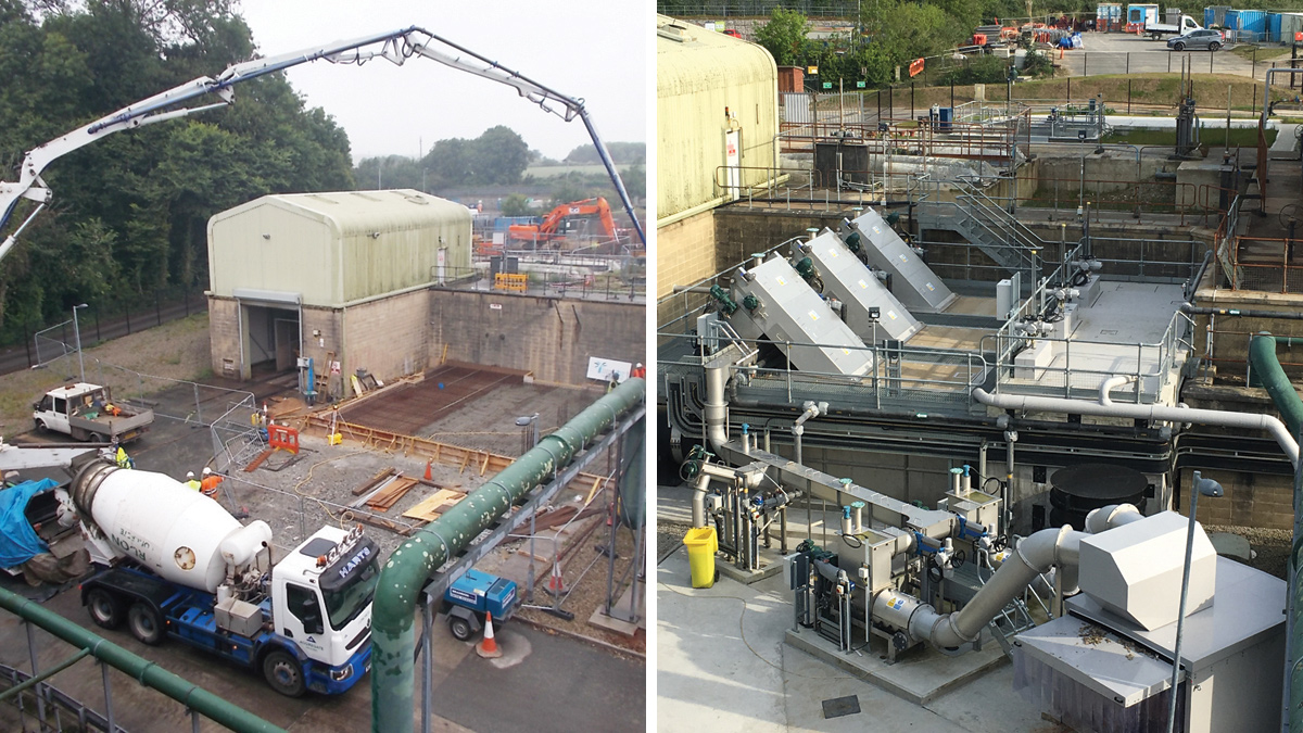
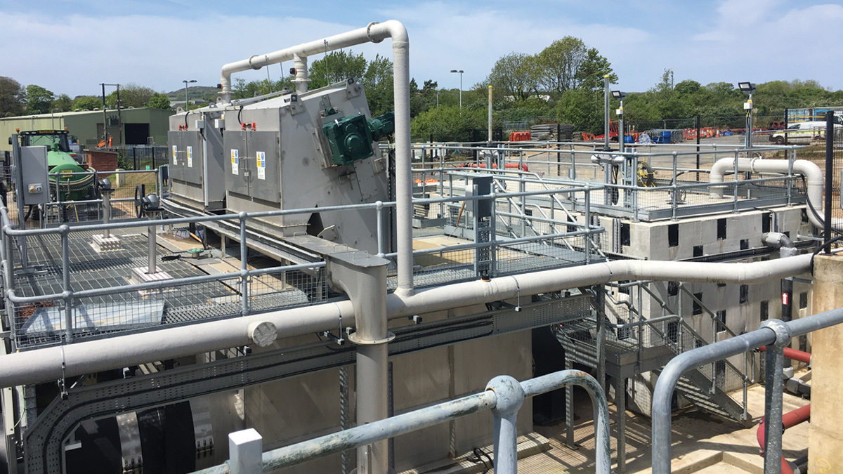
(left) fine screen civil construction works and (right) fine screen works completed – Courtesy of SWW Delivery Alliance H5O
Grit plant construction
- Clearance/enabling:
- Trial holes and investigations to locate existing services.
- Removal of existing RC road.
- Excavation:
- 13 x 9m x 4.5m deep shored with sheets and frames to enable the construction of the deepest part of the structure.
- The in situ RC structure was built with a traditional Internal shuttering system with an earth supported sacrificial external shutter.
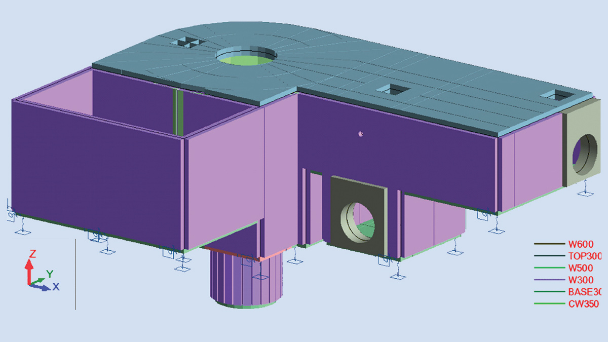
Grit trap pile design analysis – Courtesy of SWW Delivery Alliance H5O
(left) Grit trap excavation and (right) grit trap completed – Courtesy of SWW Delivery Alliance H5O
To protect the in situ RC structure from effects of the H2S, Cemprotec E942 was sprayed to all the internal cementitious surfaces.
The final section of the new Inlet works is a 90m long 2.5-4m deep 1200mm internally welded Weholite® pipe, which has a flow meter and chamber within its length, and outfalls the flows at the existing interstage pumping station. The design was excellently done by navigating the pipe between the existing services which had been surveyed using GPR and basic manhole investigations to confirm positions and depths.
Installation of this pipe was carried out within trench boxes, and sheets and wailers where required, due to service crossings, all within the busy haulage route through the live treatment works.
Coarse screen area completed – Courtesy of SWW Delivery Alliance H5O
Removal of excess material from site would have been extremely difficult due to the restricted routes and increase in time and cost, notwithstanding the environmental impact. During the construction development phase, the Interserve site team, along with the designer, proposed the reuse of this material and they were subsequently able to reuse up to 90% for screening bunds.