
Woolston WwT Scheme – Part 3 (2018)
Woolston WwTW - Courtesy of Southern Water
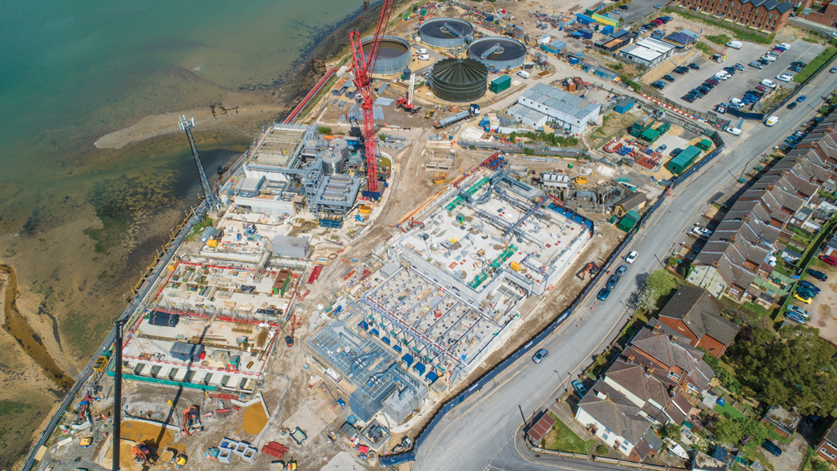
Built in 1966, Woolston Wastewater Treatment Works (WwTW) uses a conventional Activated Sludge Plant (ASP) to treat sewage flows from part of the Southampton conurbation. Serving a population of approximately 62,000, the site occupies an area of 1.26 hectares. The existing sewerage system which feeds into the WwTW collects both wastewater and stormwater from the Woolston catchment area. At present wastewater is continuously treated and the treated effluent discharged into the River Itchen Estuary through the final effluent outfall. Existing storm and final effluent discharge points will remain unchanged during the works. The new treatment process will treat flows up to 36.9MLD, in compliance with the new discharge permit requirements. All new permanent processes will remain within the boundary of the existing site.
This is the fourth paper in a series of case studies detailing the project. The third year of the Woolston WwT Scheme (2017) and earlier articles are all available on this website.
Existing site
Woolston Wastewater Treatment Works includes the following stages and processes:
- Inlet works comprising:
- Coarse and fine screens and screenings processing.
- Fat, Oil, Grease and Grit, (FOGG) removal and processing.
- High rate primary sedimentation lamella process.
- Membrane Bioreactor (MBR) plant comprising:
- Modified Ludzack Ettinger (MLE) activated sludge plant (ASP) for the biological removal of nitrogen.
- Membrane filtration tank, utilising microfiltration hollow fiber membranes.
- Existing ASP converted into a storm tank.
- Odour control comprising of chemical scrubbing and carbon units.
The sludge recycling includes:
- Sludge storage and blending.
- Indigenous sludge dewatering and processing.
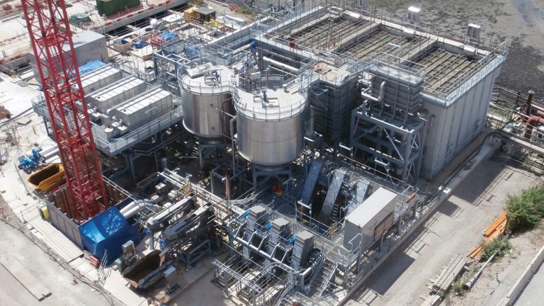
Primary treatment process plant – Courtesy of Southern Water
Improvement drivers
Woolston WwTW discharges into the River Itchen Estuary within the Solent and Southampton Water Special Protection Area (SPA) which has been designated as a nitrate sensitive zone by the Environment Agency. Southern Water is required to provide nitrogen removal for the Woolston catchment to comply with the European Urban Wastewater Treatment Directive (91/271/EEC) and associated Urban Waste Water Treatment (England and Wales) Regulations 1994 as well as nitrogen removal requirements under the habitats directive. A new effluent discharge permit requirement of 15mg/l total nitrogen (TN) has been imposed as part of a coordinated strategy involving changes at other wastewater treatment works.
Dispersion modelling predicts that the impact due to odour from the existing wastewater treatment works at Woolston is substantial and extensive. Once the installation is completed, with a stack on the primary building for the central odour control facility, all ground level impact remains below the target value of 1.5ouE/m3 at all locations.
4Delivery, a joint venture between Veolia Water Technologies, Costain and Stantec UK, is undertaking the design and construction of the project on behalf of Southern Water.
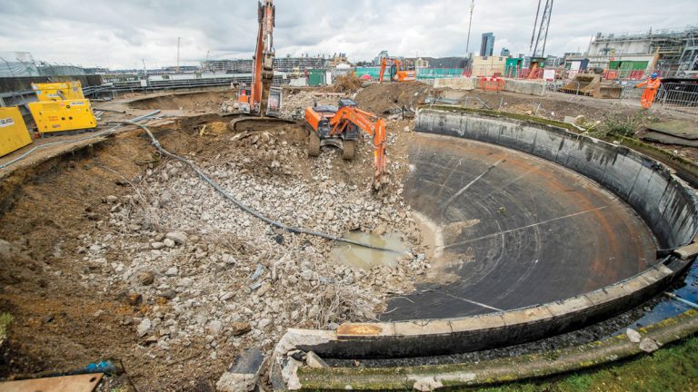
Redundant FST demolition in progress – Courtesy of Southern Water
Enabling works
The Woolston site is small and has a congested layout creating a challenging area in which to construct three large building structures. In order to provide significant programme savings 4Delivery and Southern Water have leased an area of land from a neighbouring development owned by the Homes Agency (HA).
The enabling works has been constructed and were commissioned in December 2015. These process units provide temporary primary treatment of wastewater, stormwater storage and sludge storage to allow Southern Water to continue to meet their environmental permits whilst construction within the extents of the Woolston WwTW site are completed.
Secondary treatment (ASP) within the existing Woolston WwTW site is used to complete the treatment of wastewater whilst the new primary and secondary treatment processes are constructed. Demolition of the existing process units took place in early 2016.
Once the permanent process streams are commissioned, the enabling works primary settlement tanks (PST) will be utilised as part of the secondary treatment to allow the existing final settlement tanks (FST) to be demolished. This creates the opportunity of constructing the new sludge facilities ahead of the programme providing an additional project saving.
Turn of flows
The installation of the mechanical and electrical equipment within the primary area and parts of the secondary area were completed in early 2018. The necessary hydrostatic testing, snagging and commissioning were then carried out in order to be able to turn flows from the temporary enabling works through the new plant and achieve the first major regulatory requirement set by the Environment Agency.
Having now turned flows the incoming flow passes through the new primary processes to the anoxic zone of the ASP. This has enabled the remaining now redundant existing process units to be demolished or developed in line with the permanent works design.
The existing FSTs have been demolished to make way for the new sludge building and the existing ASP is currently being converted into the storm tank.
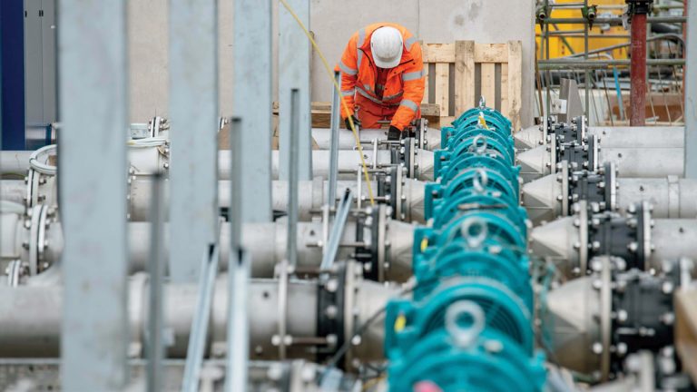
Installation of MBR pumps – Courtesy of Southern Water
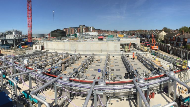
Membrane bioreactor (MBR)
The MBR process at Woolston was primarily selected based on the limited site footprint. The MBR process provides a separation barrier, replacing the requirement for sludge settlement using FSTs.
This in turn removes the limits for reliable settlement and allows the activated sludge plant to operate with significantly higher mixed liquor suspended solids (MLSS) of around 8,000mg/l. To ensure reliable operation of the membranes the incoming effluent flow requires significant preliminary treatment consisting of 1.5mm ultra-fine screens and fat, oil and grease removal plant together with a number of membrane cleaning mechanisms and allowances including high flow recirculation (four-times the treated flow), flow back pulsing, aeration scouring, citric acid and sodium hypochlorite chemical cleaning.
These requirements combined with the nature of diurnal flow patterns to the works result in a relatively complex control requirement to manage the operation of the system when compared with a conventional ASP. Together, this combination of requirements resulted in around ten installation subcontractors working in this area during the MEICA installation phase.
Membrane pipework installation – Courtesy of Southern Water
To incorporate the 40 (No.) hollow-fibre MBR modules into the precast civil structure whilst achieving a number of process parameters, stainless steel traverses were required in order to support and suspend the modules in the sludge liquors. These MBR traverses were combined with access flooring to facilitate the access, lifting and maintenance activities associated with the process.
To ensure the process tolerances were achieved, the 40 (No.) identical level adjustable traverses were accommodated inside a periphery of interfacing fixed flooring side plates. Surrounding channels were covered using GRP flooring due to its ease of workability and reduced cost.
To ensure an accurate fit on site, an as-built laser scan of the tanks was undertaken and dimensions were tailored prior to fabrication off site of all required elements. This pre-work largely reduced clashes and re-work requirement and allowed for a smooth installation.
As of April 2018, the tanks are prepared to receive the modules. In the following weeks a just-in-time delivery approach of modules will be applied. The modules will be delivered, assembled with their traverses and associated connections before lowering into their final position.
Once complete, pressure and leak testing will be performed before commencing wet testing of the modules. Turn of flows to this treatment area will follow shortly after. A period of flow and level control optimisation will then be required before the conversion to a denitrifying process with a view to achieving the new works consent permit by late 2018
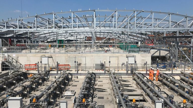
Building steelwork
As part of the planning conditions for the scheme, the treatment processes are to be housed within architectural enclosures to provide visual and acoustic screening for nearby residents. The design concept for these enclosures was developed early-on in the scheme in order to achieve buy in from planning stakeholders.
3D model showing all building steelwork – Courtesy of Southern Water
This effectively froze the ‘envelope’ of the structures in advance of full development of the internal layouts, hence efficient use of space was key throughout the design.
The three building designs consist of steel-framed structures with an aluminium cladding system. The architectural design of all three buildings avoided use of straight-lines and sharp corners, creating geometrically interesting profiles in sympathy with the local built environment.
The steelwork for these structures is supported on a piled foundation shared by the process equipment. This created a number of interfaces between individual steel members and elements of process equipment. As a result, development of the steelwork design had to be coordinated closely with the mechanical and civil design.
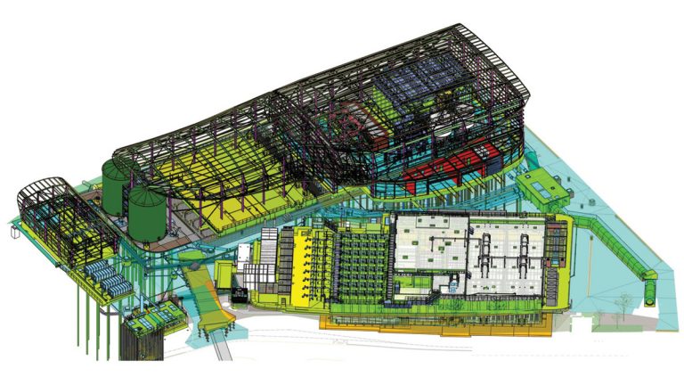
Use of the fully-federated 3D model was key to ensuring the building design did not occur in isolation. This enabled the design team to manage and avoid clashes and identify areas where the building structure could be utilised for support of plant and equipment. Once a working structural general arrangement had been developed, the federated 3D model was issued to the nominated steelwork subcontractor for detailed design development.
Secondary building steel-framework installation in progress – Courtesy of Southern Water
By having access to a more complete picture of the overall layout, the subcontractor could progress the design with cognisance of other elements and avoid compromising the internal layout.
The model was also used to define the positions of load interfaces. For example, odour removal and ventilation ducting support positions could be reviewed with accuracy and captured within the steelwork finite element model. Coordination with the cladding subcontractor occurred entirely through use of the 3D model to define the purlin layout and fixing requirements.
Following construction of the concrete foundation, the cast-in holding down connections for the columns were surveyed and fed back into the steel model and ensure any tolerance issues could be captured at design stage.
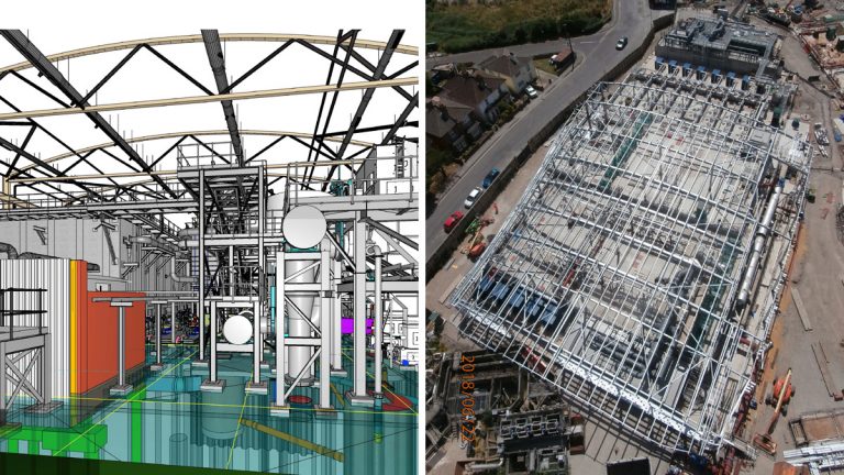
(left) Model image from inside of the primary building and (right) secondary building steel-framework installation in progress – Courtesy of Southern Water
In the interest of hitting programme milestone dates, the process equipment was required to be constructed and commissioned in advance of the steelwork installation. This presents a significant challenge to the steel erection team work above live process equipment. The federated mechanical and civil model has been provided to help plan this stage of the works by assessing access points and space availability for craneage.
The complex geometry of the buildings has presented a challenge for the cladding manufacturers in terms of achieving the required curvature on some facets of the buildings. However, this is being tackled through use of the Bemo-Monro® system which uses the 3D model geometry as an input for precision-controlled fabrication equipment to create the require curvature on the standing-seam panels. The end result is hoped to be a well-considered an integrated building layout, with a modern external finish.
Woolston WwT Scheme : Designers, contractors & main suppliers
- Designer & contractor: 4Delivery Ltd
- Lamella: Paques bv
- FOGG removal/processing plant: Veolia Water Technologies
- FBDA, MBR aeration: Suprafilt
- MBR: Koch Membrane Services
- Odour, HVAC: Air Technology Systems (ATS)
- Structural steel buildings: Peers (framework) and Prater (cladding)
- Steel fixing, formwork, concrete: NJ Doyne Construction Ltd
- Groundworks, drainage, pipework: Davey Civils Ltd
- Precast concrete structures: Carlow Precast Concrete (now FLI Precast Solutions)
- MCCs: MCS Control Systems
- Mechanical Installation: A&J Fabtech and Woodhams MEC Ltd
- Electrical Installation: Interface Contracts Ltd (ICL)
- Supply & installation of tanks: Stortec Engineering Ltd
NB: The above are the main contractors, sub-contractors and suppliers. There were multiple other packages for smaller values
Current status
The Woolston WwTW redevelopment achieved a key milestone in June 2018 when flows were turned through the new MBR. This was a significant achievement in the redevelopment project and met a crucial interim Environment Agency regulatory date.
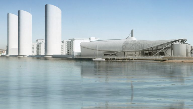
Woolston WwTW visualisation – Courtesy of Southern Water
This was the third regulatory date successfully achieved on the project, bringing into use major elements of the process stream. The MBR plant is particularly notable as it is one of the largest and most technically advanced to be built in the UK. Recent final effluent samples indicate that even at this early stage the plant is operating effectively. The redevelopment team will now focus on achieving take-over and the final regulatory consents by May 2019.