
Huddersfield Energy & Recycling Facility (2020)
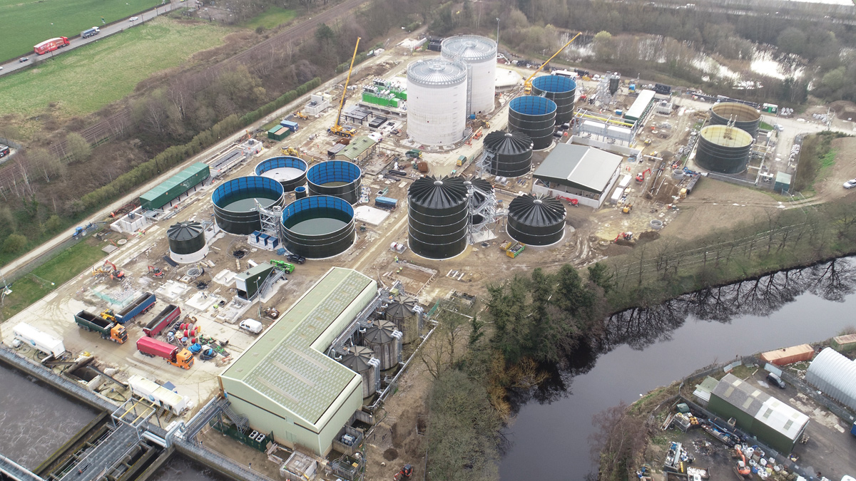
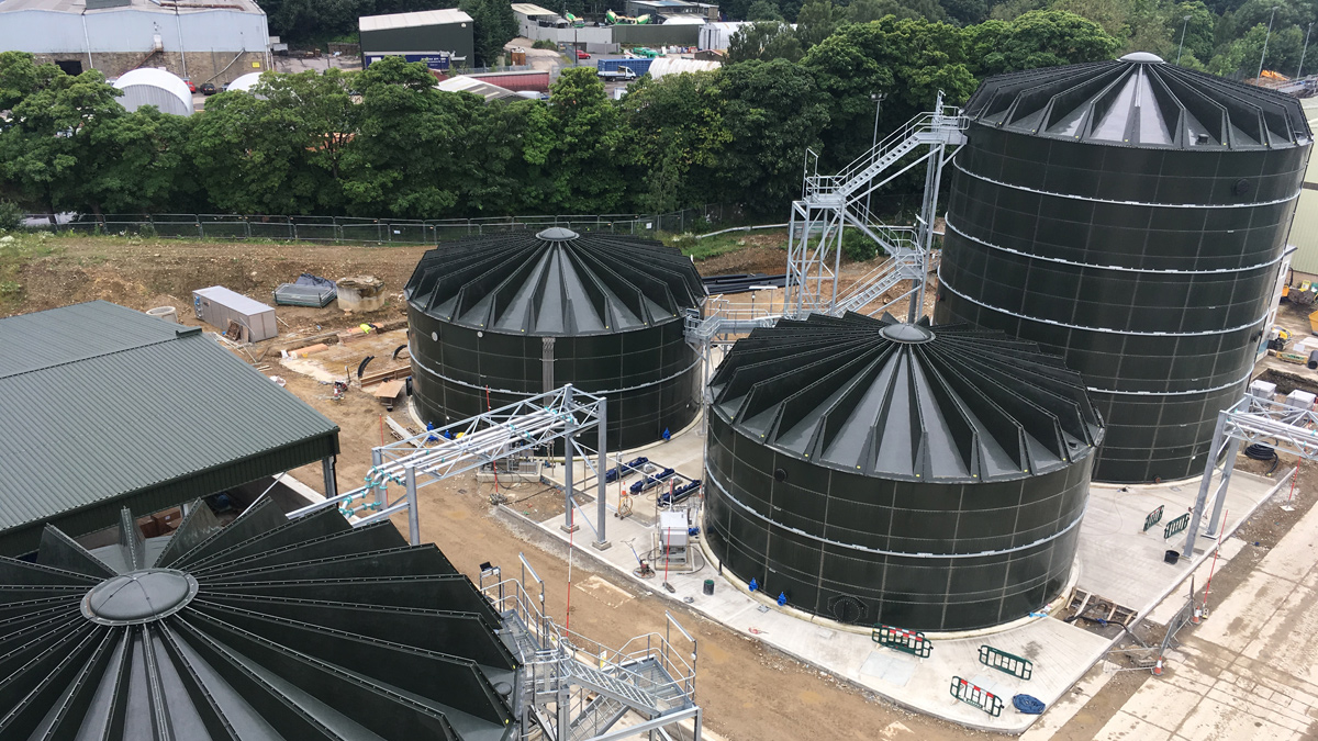
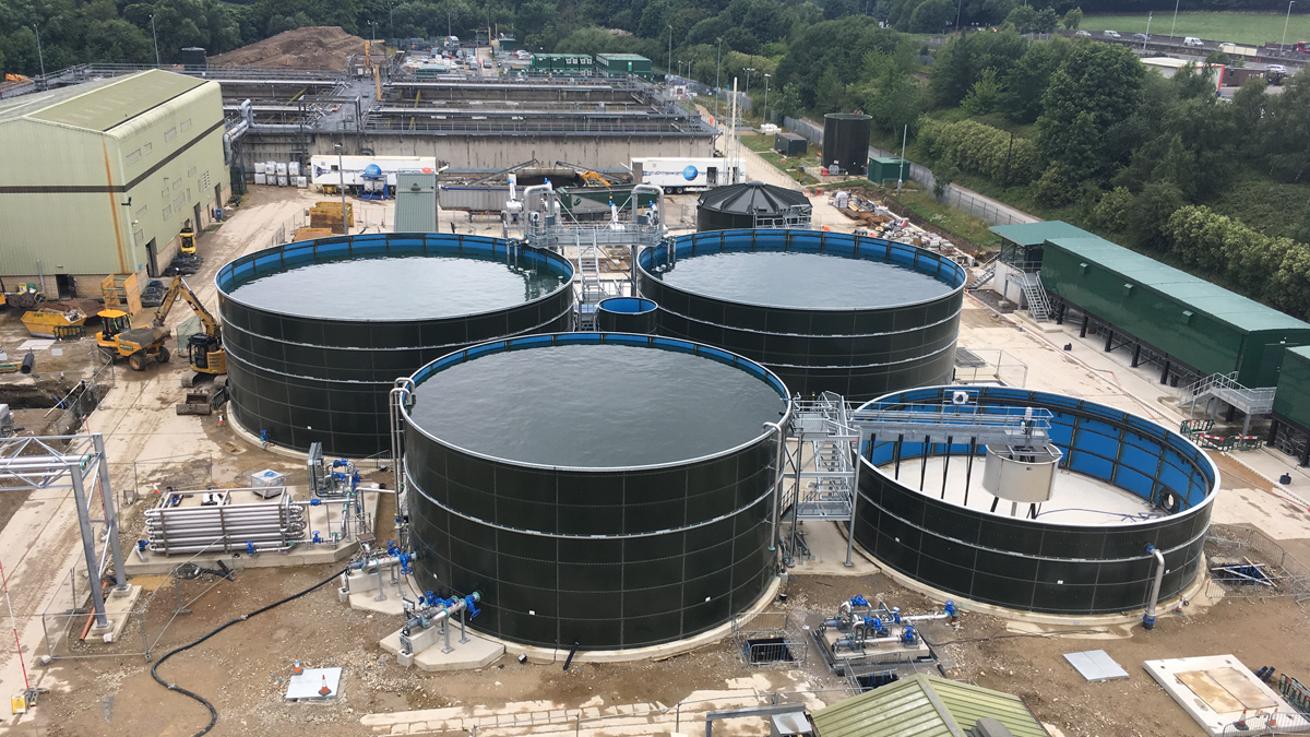
General view of Huddersfield E&RF under construction - Courtesy of YWS
Huddersfield Energy and Recycling Facility (Huddersfield E&RF) is in Mirfield on Yorkshire Water’s Upper Brighouse site. The project involved the demolition of the existing incinerator and construction of a new mesophilic anaerobic digestion facility that will produce electricity; equivalent to powering 5280 homes once it is fully operational. The primary drivers for the scheme were:
- Replacement of the existing incinerator.
- Production of electricity to reduce Yorkshire’s Water carbon footprint.
- Improving the sludge strategy for the Yorkshire Water region by moving to 100% anaerobic digestion.
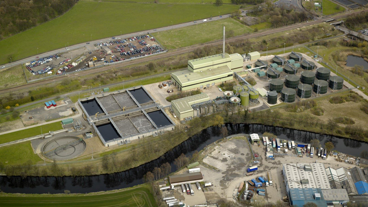
Calder Valley Sludge Incinerator with its 63m tall chimney before flooding and subsequent demolition – Courtesy of www.Petersmith.com
Background to the project
Sludge treatment in the Huddersfield and Brighouse conurbation was previously provided by incineration in the Calder Valley Sludge Incinerator (CVSI) at Yorkshire Water’s Upper Brighouse site. The CVSI installation was one of seven treatment facilities within the Huddersfield and Brighouse conurbation which YWS have been rationalising over time to ensure best value for customers. The incinerator facility included thickening and dewatering facilities as well as extensive storage capacity.
The incinerator had been operational since the early 1990s and it was catastrophically damaged in the severe floods of Boxing Day 2015. Following a strategic review, Yorkshire Water Services (YWS) decided to replace the incinerator with conventional mesophilic anaerobic digestion (MAD) facility supported by lime sanitisation of the digested product to secure the long-term treatment of sludge for the area. The change in treatment direction brings the benefit of renewable generation from biogas production and increased reliability and performance. The total cost for the project is £50m.
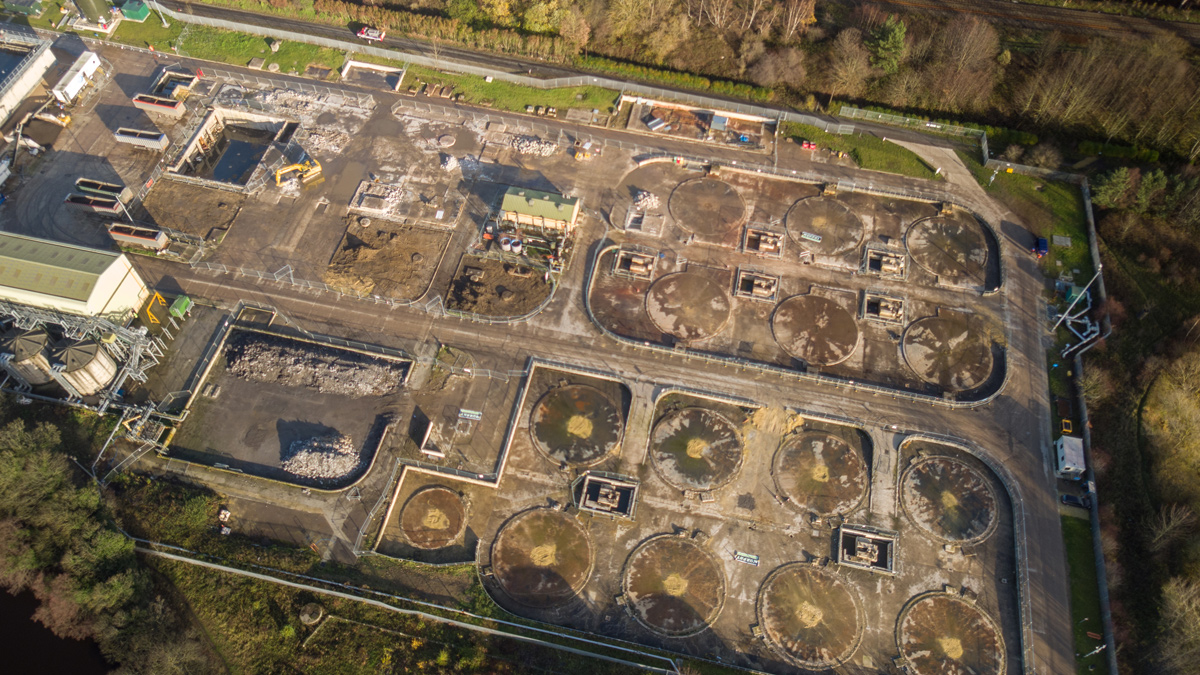
Upper Brighouse post demolition of incinerator – Courtesy of YWS
Initial assessments
Following the flood damage to the incinerator, YWS went out to the wider market, through OJEU tender, rather than utilise the existing framework options. Arup were appointed to undertake an initial assessment for the sizing and design of the new facility, which included:
- Extensive digestion trials; due to the nature of the incoming sludge and to ensure that the final product would be suitable for re-use in agriculture.
- Agreeing the site layout for planning purposes.
- Flood risk analysis.
- Development and confirmation of the energy strategy.
- Developing the tender and contract scope.
This information was then used to inform the tender process. Three contractors were selected to participate in the detailed assessment following the initial OJEU notification. The project was let under a NEC 3 Option A Contract.
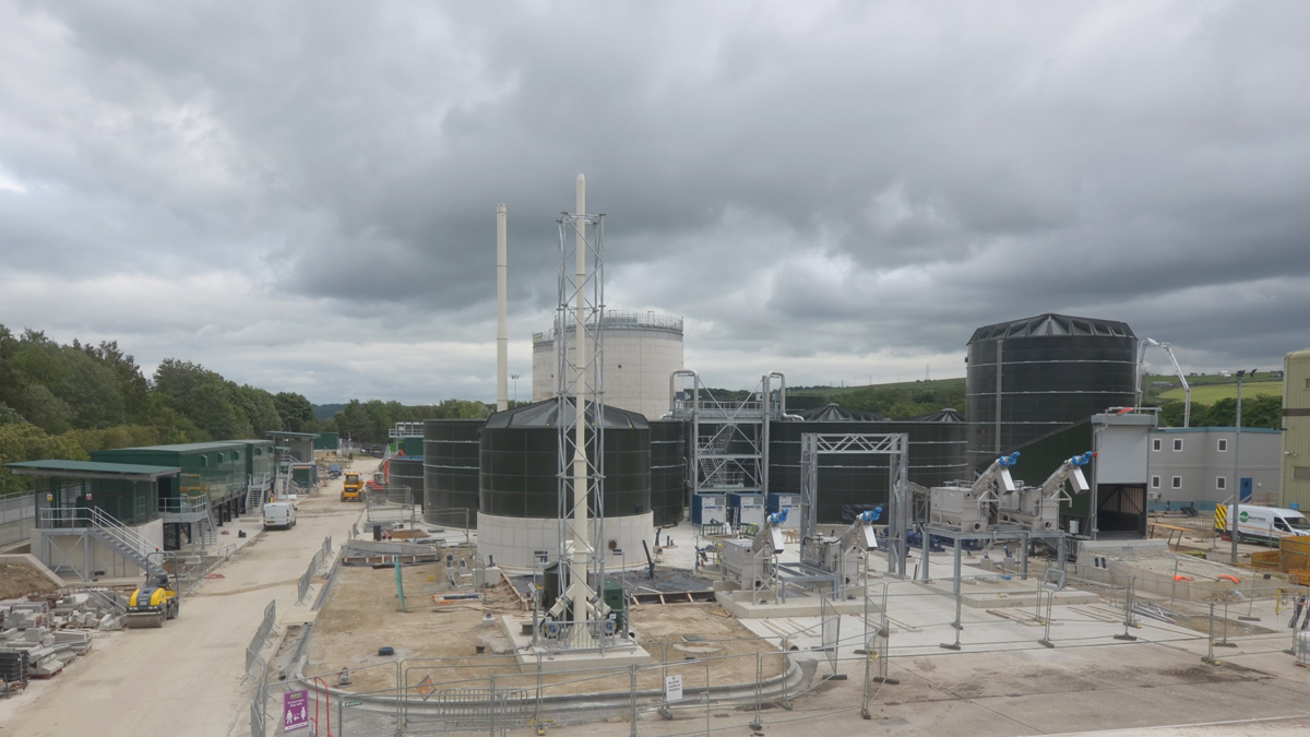
Sludge imports facility under construction – Courtesy of YWS
Procurement Process
J. Murphy & Sons Ltd (JMS) were selected by YWS to design, construct and commission the new Huddersfield Energy & Recycling Facility. JMS are providing YWS with a full end to end service including civil construction and PMEICA design and installation together with process testing & commissioning provided by Murphy Process Engineering (MPE).
Huddersfield Energy & Recycling Facility: Supply chain
- Design & build contractor: J. Murphy & Sons Ltd
- Process, mechanical & electrical contractor: Murphy Process Engineering
- Process safety consultants: SWECO
- Civil design consultants: GHD
- Control panels: CEMA Ltd
- Electrical installation: Murphy Electrical Services
- Tanks: Balmoral Tanks
- Cake reception unit: Samson Materials Handling Ltd
- Sludge screens: Huber Technology
- Liquid poly system: Northern Pump Suppliers
- Drum thickeners: Alfa Laval Ltd
- Digester mixing: Landia UK Ltd
- Heat exchangers: HRS Heat Exchangers Ltd
- Gas holder: AJ Tensile Biogas Systems Ltd
- Waste gas burner: Uniflare Ltd
- Siloxane removal: Higgins & Hewins Ltd
- Large scale blending (back mixing) and thickened sludge transfer open hopper T range PC pumps (HERF): SEEPEX UK Ltd
- CHP: Clarke Energy
- Boiler: Shaw Renewables
- Powder poly system: Richard Alan Engineering
- Dewatering centrifuge: Alfa Laval Ltd
- Return liquor treatment plant: ACWA Services Ltd
- Odour control: Greenacre Environmental Systems Ltd
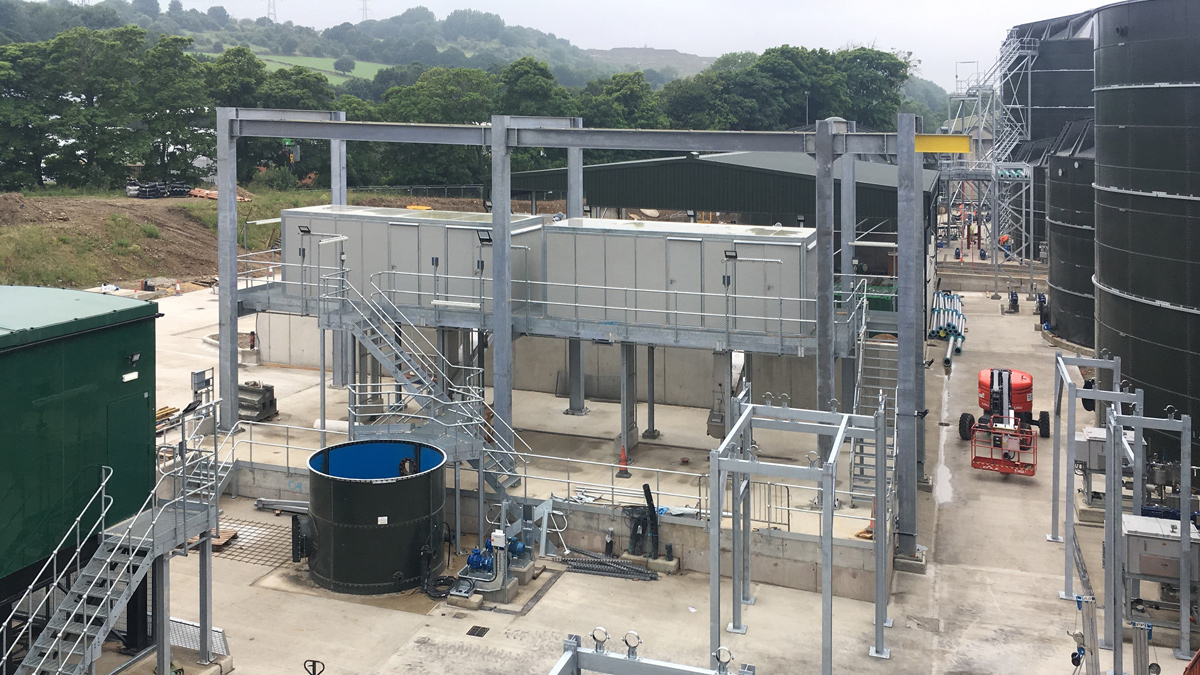
Sludge thickening process area under construction – Courtesy of YWS
Project scope
The new Huddersfield E&RF will be a regional sludge treatment facility receiving indigenous and imported sludge in both liquid and cake forms. The digested sludge will then be lime sanitised to pH9 and dewatered on site before export to land. The scope of the project is to provide:
- Imported sludge delivery points for cake and liquid sludge: The imported liquid sludge is discharged to the sludge screen feed tank before screening. Sludge cake is received at the cake reception plant where it is re-watered to 6 % DS.
- Imported sludge screening: Liquid sludge will gravitate from the storage tank through the screens before being pumped to the thickener feed tanks upstream of the sludge thickening facility. Re-watered cake will also be screened prior to being pumped to the 2 (No.) digester feed tanks.
- Combined import and SAS thickening: Polyelectrolyte will added to the sludge and be thickened to around 6% using 3 (No.) dual drum thickeners (duty/duty/standby).
- Digester feeding system: Re-watered sludge cake and thickened sludge are fed to the digester feed tanks from where it is pumped to the digesters.
- Digesters: 2 (No.) each 7,306m3 capacity. To reduce health and safety issues from working at height, the digester roofs were constructed at ground levels and lifted on top of the tanks.
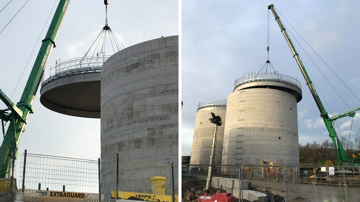
Lifting the digester roof into place on digester 2 – Courtesy of YWS
- Gas holder and handling system: This comprises pipework from the digesters to the new gas holder and from the gas holder to the CHP/boiler. A flare stack will also be provided, where excess gas that cannot be used within the process is burnt off.
- Biogas treatment: A carbon scrubber is provided for the removal of siloxanes from the biogas, prior to use in the CHP.
- 2 (No.) 1.2 MW CHPs: These will be the primary users of the biogas from the process. The CHPs will generate electricity to reduce the site reliance on imported power and the waste heat from the CHP will be used to heat the digesters. This will include provision of HV equipment to pass the energy generated from the CHP forward to the external grid.
- 1 (No.) dual fuel boiler: This will operate either on failure of the CHP or to provide supplementary heat when the CHP’s are operating but cannot provide the full heat requirement. The boiler will run on biogas or natural gas.
- Exhaust stack: A 47m high stack is provided for the dispersion of exhaust gases from the boiler and CHP.
- Sludge heat exchangers: The heat exchangers will take the heat from the hot water provided by the CHP/boiler and transfer it into the sludge contained within the digesters. This will ensure that the digesters are operated in the temperature range 36-39°C.
- 2 (No.) dewatering feed tanks: Digested sludge is transferred by gravity to these storage tanks.
- Lime addition: Sludge is pumped from the dewatering feed tanks to the lime mixing tank. Powdered quick lime is added, to raise the pH of the sludge, increasing biological inactivation, so that conventional product status is achieved.
Sludge dewatering centrifuges during construction – Courtesy of YWS
- 2 (No.) dewatering centrifuges: The centrifuges will dewater the limed digested sludge to around 25% prior to loading onto HGVs for export.
- Final product storage: A cake barn provided storage for 844m3 of sludge cake.
- Liquor treatment plant: The E&RF will have a purpose-built liquor treatment plant (LTP) which is based on the Amtreat® process (supplied by ACWA). The ammonia levels from the LTP will be reduced by 85% prior to returning to Lower Brighouse STW such that the liquors do not have a detrimental impact on the existing activated sludge process.
- Odour control: Two odour control plants are provided. OCU 1 is dedicated to air extracted from the cake reception facility. OCU 2 caters for air extracted from the sludge thickening plant, filtrate PS and associated tanks.
- Welfare and laboratory facilities: JMS will also provide a new control building, welfare and lab facilities for the site. The control building for the site was built off site and dropped into place allowing the construction of the building to run parallel with the main site.
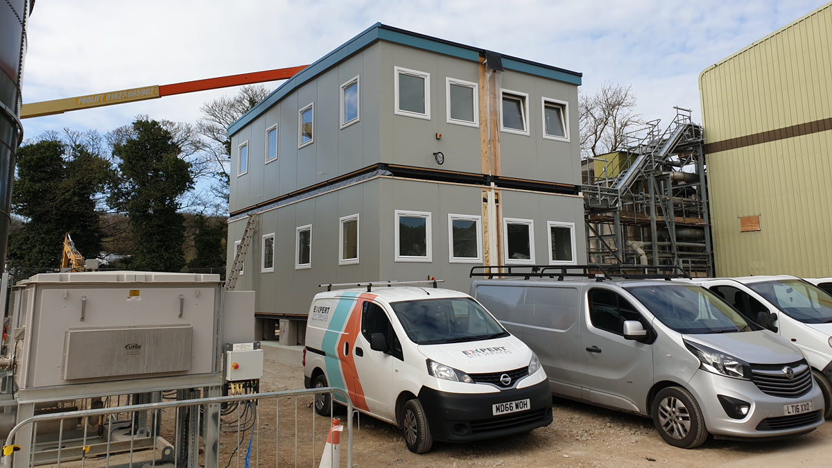
Modular control building fabricated off site and installed in one – Courtesy of YWS
Project constraints
Air quality and odour control: The site is in an air quality management zone, primarily due to local traffic congestion and is the controlling factor in determining the height of the boiler and CHP exhaust stacks. Dispersion modelling was used to determine that the stack would need to be 47m high and all the supporting data was submitted as part of the planning application.
Low odour complaints need to be maintained; therefore, the new installation would need treatment at key locations to ensure that there are no odour complaints in the future. Dispersion modelling was used to optimize the treatment systems which concluded that several small units serving specific assets would be more effective than a wider general system.
Flooding considerations and protection of key assets: The planning process required a flood risk assessment to be undertaken. It was demonstrated that the layout of the new development affected the flood routing and impacted the downstream water levels. As such landscape bunds were strategically positioned to slow flood water moving across the site and ensure that there was no detrimental effect.
The 2015 floods showed that it would be necessary to account for future flood events in the design. Key assets and plant would need to be positioned such that after future flood events the whole site could remain operational. The whole site could not be protected from flooding, so mitigation measures were included for these assets. Examples included transformers, CHP engines and the boilers all being raised above the design flood level.
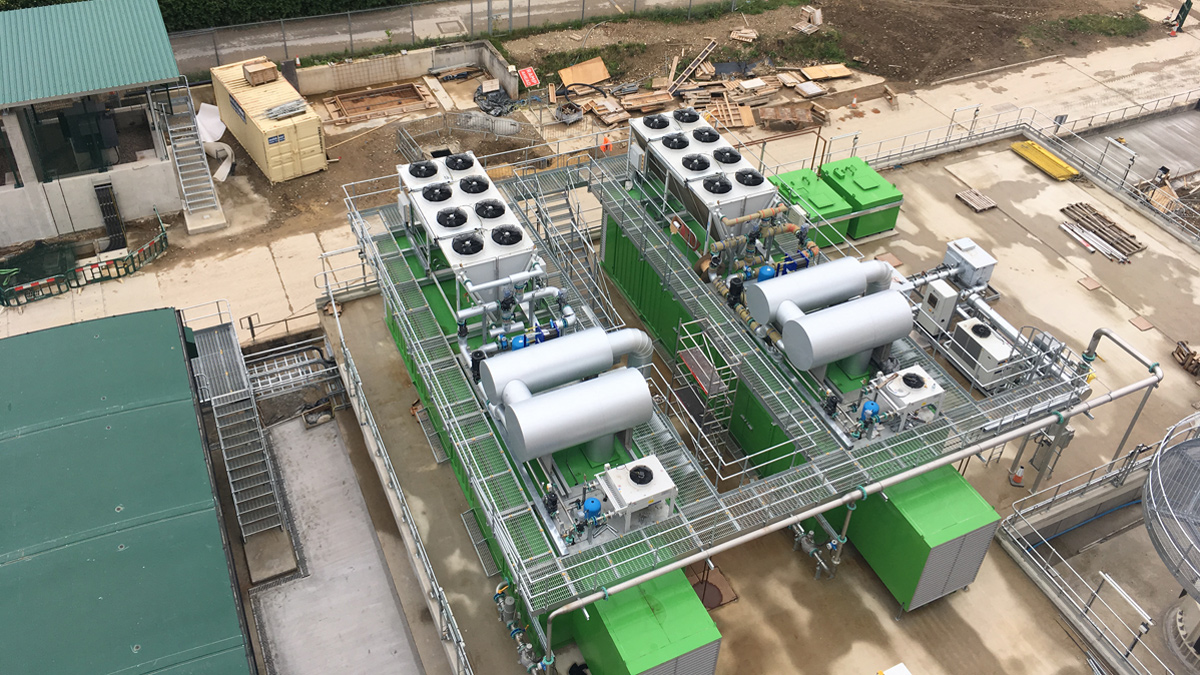
CHP’s on elevated platform under construction – Courtesy of YWS
Environmental permit: At the end of 2018, after commencement of the works, new regulations were introduced for environmental permits and the Environment Agency’s Best Available Techniques (BAT) methodology needed to be adopted. This involved redesign of pipework out of tank bases, a site wide bund and dual containment pipework.
Technical excellence/innovation
The design includes a flood protection strategy whereby critical assets are installed above the flood defence level. The design has also used the limited space available efficiently to ensure that the operation and maintenance of the new equipment is not compromised. JMS has been able to rationalise the site layout to give:
- A single area for unloading of imported liquid sludge and sludge cake.
- Designated areas for unloading of liquid chemical deliveries of polyelectrolyte, lime and anti-foam chemicals.
- A one-way system around the dewatering area providing unimpeded traffic flow for sludge tankers and also chemical deliveries.
- A raised gas bag is provided so that the condensate pots on the gas pipework are not located below ground level and thus this will avoid confined spaces.
- A flood protection strategy to protect critical items of plant including LV MCCs and switchgear, gas holder and gas burner, boiler and CHPs, and the product storage barn.
Return liquor treatment plant under construction – Courtesy of YWS
GHD has provided civil engineering design support, collaborating closely with the JMS site team. The resultant value engineered plant support structures are now above flood level where required, and incorporate precast concrete elements to reduce the need for in situ reinforced concrete. The solution has a lower carbon footprint through reduced vehicle deliveries of wet concrete, formwork and reinforcing bars. Other value engineering has been delivered through:
- Auto-tracking software to optimise vehicle movements around the site, assisting in locating the plant to reduce the hardstanding areas.
- Reuse of the existing below ground drain system, including the return liquors pumping station, to minimise the need to break out large quantities of the existing concrete site roads.
- Production of a Materials Management Plan to maximise reuse of site won materials and reduce carbon footprint. Use of crushed concrete from the demolished incinerator building avoided the need to import materials and reduced vehicles movements.
- Coordination of the underground services, drainage, process pipework, potable water supply, electrical ducting to eliminate clashes during installation works.
- Production of dual containment details and design of all impermeable areas to obtain approval by the Environment Agency under the Industrial Emissions Directive.
- Using the Converge Concrete Monitoring System in the top pour of the digester tanks to monitor the temperature of the concrete, allowing the team to know when the concrete had reached appropriate maturity.
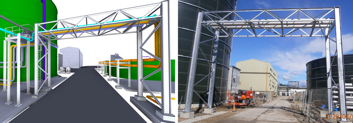
(left) 3D render of pipe bridge from the digester feed tank to the return liquor treatment plant area – Courtesy of Murphy Process Engineering, and (right) and as built – Courtesy of YWS
3D modelling
MPE have implemented the use of 3D modelling on the project. The primary model use is coordination, and the model is shared with site teams on a weekly basis.
Point cloud scans are utilised to verify site information and to ensure the project information model is up to date and clash free. The model is shared and coordinated with subcontractors to facilitate off site fabrication of pipe bridges, process pipework and pipe support racks.
Programme and current status
The start date for the project was September 2018 and the digesters will be fully operational by May 2021, with a planned completion date for the works in August 2021. At the time of writing (July 2020) the scheme is in the construction stage, with all structures now built, and process commissioning is currently planned for December 2020.
The project has seen some impact from the coronavirus pandemic resulting in some delays due to the supply chain shutting down. The site is now back to pre-COVID-19 levels of progress.
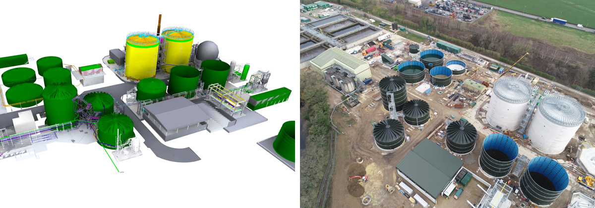
(left) 3D render of the site – Courtesy of Murphy Process Engineering, and (right) as built – Courtesy of YWS
The digestion site in numbers
- The sludge load to the digesters is 24,000tDS/annum or 65.753tDS of sludge per day, including up to a maximum of 11.880tDS per day of imported liquid sludge and 25.831tDS per day sludge cake respectively.
- Two CHP will be provided each with a peak electrical output of 1,195 kW and a thermal output of 1,203 kW.
- The volume of each digester is 7,306m3.
- The total gas production from the digesters will be up to 22,192Nm3/d.
- The capacity of the gas holder will be 2,000m3.