Rivelin WTW – Sirofloc Replacement: Part 2 (2018)
Mott MacDonald Bentley - MMB
Yorkshire Water Services (YWS) committed to the Drinking Water Inspectorate’s (DWI) compliance date of 31 December 2017 for beneficial completion of a new clarification process at Rivelin WTW. The £25m scheme required the design and construction of a large 82.5MLD buried treatment plant (80m long, 40m wide and 14m high) on the border of the Peak District National Park, an extension to the existing rapid gravity filter (RGF) plant and various wash water recovery upgrades including a new thickener. A contract was awarded to specialist design and build contractor Mott MacDonald Bentley (MMB) in late 2015, giving just over two years to deliver the works and achieve the designated compliance date. The regulatory date was achieved and the plant has since demonstrated a significant improvement in the quantity and quality of the drinking water into supply.
Project drivers
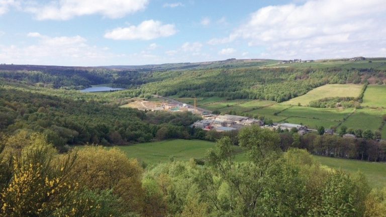
Rivelin WTW provides drinking water for a population of approximately 200,000. The raw water feeding the works is a blend of water from the Derwent Valley via Ladybower Reservoir and the local catchment via Rivelin Reservoir. The quality of the raw water has deteriorated in the period since the current plant was built in the early 1990s and therefore investment by YWS was needed to ensure the treatment works would continue to reliably process the higher colour in the raw water entering the site. Areas of the water network can only be supplied from the Rivelin works, limiting shut-downs and increasing the criticality of the works.
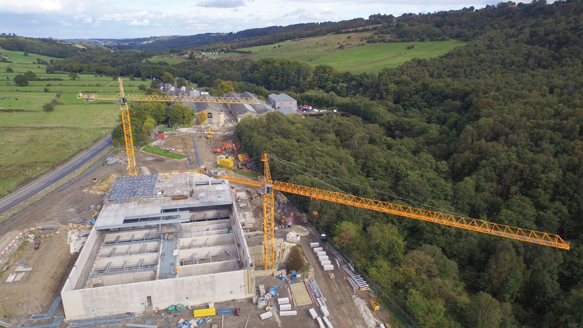
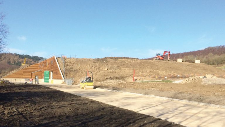
Picturesque location of the new facility at Rivelin WTW – Courtesy of MMB
Planning
Rivelin WTW is located near Sheffield on the border of the Peak District National Park. Given the sensitive location of the works, the planning process was identified early as a major project risk. Two options were considered for the new facility: above-ground and buried. Following extensive consultation with stakeholders, which included local residents and the Rivelin Valley Conservation Group, the preferred buried design was developed to have minimal visual impact. The building compromises a concrete sub structure and outer walls with steel internal columns and roof support beams. The new structure has been constructed on land adjacent and to the west of the existing works and is buried on three and a half sides to obstruct it from public view. All the excavated material has been retained in order to backfill and landscape the site. The green roof will be sown with a wild flower meadow seed mix and careful planting of trees will further blend the site into its surroundings.
Process design
A new floc blanket clarification process stage has been constructed capable of treating 82.5 MLD to a design envelope of 199 Hazen and 20 NTU. The process is fed via gravity from the existing inlet works and hydrogenator, making use of the available head within the system and therefore avoiding additional interstage pumping. New chemical storage and dosing facilities are located within the building for dosing of sodium hydroxide, ferric sulphate and polyelectrolyte upstream of the clarifiers. The raw water is pH adjusted and ferric sulphate coagulant is dosed based on the inlet flow and raw water colour. The flow then enters hydraulic flocculation lanes before being dosed with polyelectrolyte to promote the formation of larger floc.
The flow is then equally split between the in-service clarifiers. The 7 (No.) clarifiers are flat bottomed and have an up-flow between 1.7 to 2.4m/hr. Each clarifier has 4 (No.) de-sludge cones discharging to a central gallery. Clarifier desludging is flow paced to optimise the loading on the water recovery plant. Distribution of the inlet flow to a clarifier is delivered through 120 (No.) nozzle outlets close to the clarifier floor to achieve near to linear up-flow through the clarifier.
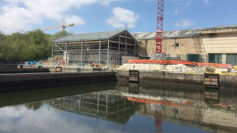
Extension to existing RGF building for 3 (No.) new RGFs – Courtesy of MMB
Further to the construction of the new clarification plant the following site upgrades have been undertaken:
- 3 (No.) new rapid gravity filters connected into the existing filtration plant on site to reduce the site loading rate to 5.2m/hr. These are fed directly from the existing filter inlet channel integrating the filter flow distribution and control systems.
- Upgrades to the wash water plant capacity including increasing the backwash rate from 2000 to 2300m3/hr and the construction of an additional wash water thickener.
- New service water pumps on the existing site.
- Installation of safe permanent access as well as replacement of the filter nozzles and media within the existing rapid gravity filters.
- Addition of a sludge to sewer mixing and a sludge holding tank transfer system.
- Complete overhaul of the site start-up/shut down software.
Design optimisation
The scheme utilised BIM extensively throughout its delivery; providing a high degree of collaborative design and construction as well as driving project efficiencies. 3D models were developed during the investigation stage, further developed at detailed design and used at each milestone review, HAZOPs, HAZCONs and ALM studies. The team initiated a 3D digital cloud point survey of the existing buildings and internal pipework which was integrated into the 3D model. The employment of BIM for the scheme simplified the process of client review and approval using virtual tours to identify access arrangements for operation and maintenance staff. Further to this a CFD model was completed of the flocculation lanes, clarifier feed channels and clarification cells. This confirmed the design of the hydraulic flocculation to ensure an even distribution of flow was occurring across the clarification cells and that the flow patterns within the channels and cells would not promote the breakup of floc, optimising the process performance.
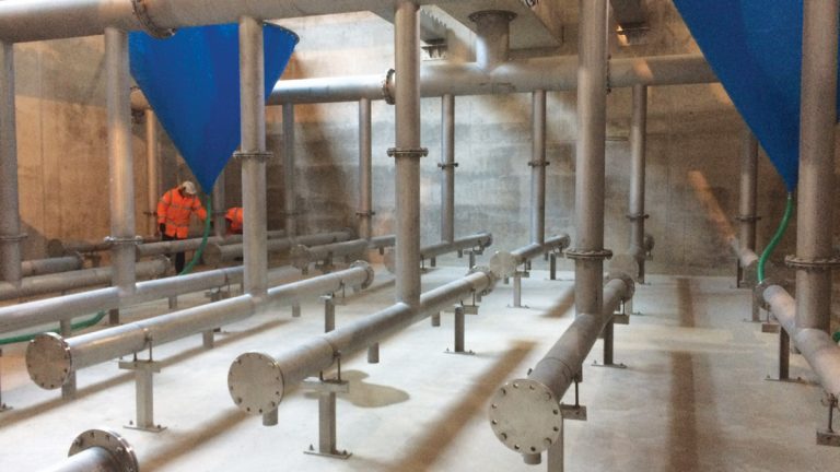
Clarifier internal pipework and sludge cone – Courtesy of MMB
Construction efficiencies
Through early engagement with the supply chain and the end users, MMB was able combine the relevant knowledge and experience to identify methods of realising additional efficiencies beyond those included in the baseline delivery programme.
- Re-sequencing of work: The wall construction sequence was amended to better facilitate access for early M&E installation. This also allowed the area of the building containing the majority of the mechanical, electrical and chemical dosing equipment to be completed first and dry commissioning commenced up front of civil completion.
- Early M&E installation: M&E subcontractors agreed to start early to achieve advanced completion, despite it being accepted that this would be less efficient in terms of use of their labour. To accommodate the early electrical installation, the MCC and chemical dosing equipment were installed prior to completion of the building roof.
- Roof installation: Collaborative planning sessions identified that the only means of completing construction on time was to re-programme the roof installation work so that this took place at weekends. This made the cranes available to the other activities full time during the week and removed the risks associated with the roof structure being constructed above other working areas.
- Clarifier access: Through the installation of submarine door access from a central gallery into each clarifier cell, safe access was provided for future operation and maintenance. This also provided safe access throughout construction, significantly reducing the amount of temporary works required, reducing cost and congestion.
- Utilisation of existing assets: Project efficiencies were realised through connecting into the existing process downstream of the hydrogenator and inlet screens. The existing sodium hydroxide delivery, bulk storage and dilution facilities were also retained and the chemical transferred to day tank facilities within the new structure. To provide air and water for backwashing the rapid gravity filter extension, the existing blowers and backwash system were connected into, and the pumps maximum backwash flow rate increased.
- Thickener construction: The additional wash water thickener was located adjacent to the existing water recovery building and was provided with a GRP cover incorporating access hatches and lighting for cleaning of the launder channel and inspection of the sludge blanket. The process was again fed by gravity and the flows dosed using the existing polyelectrolyte make up system.
Process commissioning
The commissioning procedures and durations were analysed collaboratively with Yorkshire Water and efficiencies collectively identified that would shorten the duration of testing and commissioning. During the initial process commissioning a lagoon was dedicated to flow from the new process allowing additional settlement and careful monitoring of the effluent prior to discharge to river. Upon satisfactory performance of the new process flows were blended with the existing plant onto the RGFs in order to maximise production and reduce the quantity of wasted water arising from commissioning activities. The new wash water recovery facilities were also dedicated to the clarification plant allowing careful monitoring of the supernatant produced prior to return to the process.
Completed clarifier building being buried and hidden from view – Courtesy of MMB
Performance and reliability
On the 27 April 2018 the clarification plant completed its performance and reliability trial. It has successfully demonstrated an improvement in the quality of treated water into supply and been shown to:
- Treat flows from 40 to 82.5MLD.
- Produce clarified effluent of mean turbidity <0.5 NTU.
- Achieve UV removal of > 95% or to < 2.5abs/m.
- Automatically adjust to changes in flow and set point while controlling:
- Ferric sulphate coagulant dosing to mean +/- 0.1mg/l.
- Sodium hydroxide pH dosing to mean +/- 0.05 pH.
- Polyelectrolyte dosing to mean +/- 0.0005 mg/l.
- Produce filtered effluent of <0.04 NTU for increased filter run times of > 54 hours.
The plant has been producing greater than 75 MLD since February and, due to the superior final water quality, has considerably reduced the chlorine demand in the distribution system.
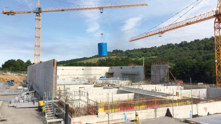
Clarifier building construction – ferric tank installation – Courtesy of MMB
Conclusion
Despite the very tight timescales set at the outset and the many challenges overcome, the new plant achieved beneficial use on 27 December 2017, allowing Yorkshire Water to confirm their regulatory undertaking before the compliance date.