

Sindlesham & Bearwood WBS Phase 1 (2026)
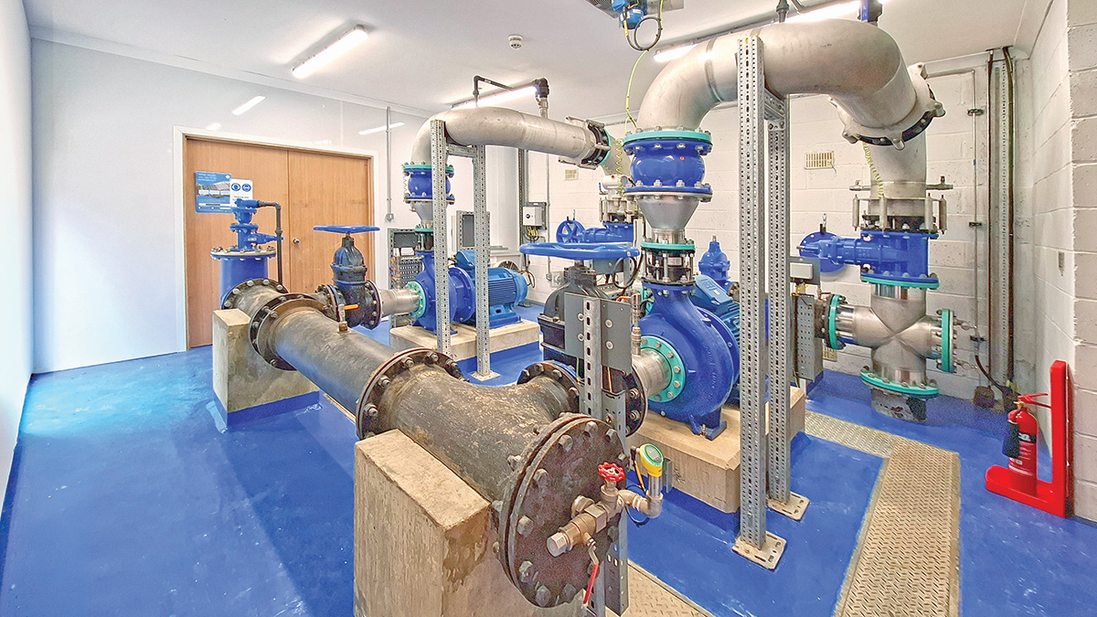
Inside the completed Sindlesham Water Booster Station - Courtesy of Ward & Burke
Major developments within the Arborfield Garrison near Wokingham, Berkshire, are currently being planned and constructed, which are anticipated to be completed by 2030. These developments comprise 3,500 new residential properties, two primary schools, a secondary school and community facilities. The developments are increasing demand on the clean water network, requiring the implementation of network upgrades and reinforcement to the Sindlesham Water Booster Station (WBS) to prevent anticipated low pressures.
Project overview, drivers & challenges
Sindlesham Water Booster Station (WBS) is fed from Early Service Reservoir (SR), boosting flows to the service reservoir at Bearwood, where a separate WBS feeds the network demand. Sindlesham WBS previously delivered approximately 84 l/s during peak demand, however, a capacity assessment completed in 2021 showed that peak demand for 2024 and beyond will rise to 100 l/s, thereby creating the project driver for the upgrades described in this case study.
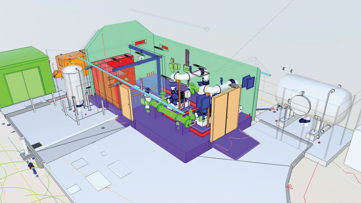
Sindlesham WBS proposed solution overview – Courtesy of Ward & Burke
The maximum permissible outage at any time for Sindlesham WBS is 2 hours, at which point the level in Bearwood SR will be such that the Bearwood WBS will be inhibited from operation to protect its assets. Furthermore, if Bearwood WBS is inhibited or not operational for any reason, there would be direct customer impact within 20 minutes. These limitations were the main considerations for the resultant upgrade solutions and construction methodology and sequencing.
Solution overview
The existing installation at Sindlesham comprised of two 18.5kW pumps, which delivered approximately 84 l/s to Bearwood SR via a 4.2km, DN300 pipeline. The solution requires two 55kW end suction centrifugal pumps in a duty/standby configuration.
A transient analysis carried out on the existing network by Hydraulic Analysis Ltd on behalf of Ward & Burke, outlined the requirement for a 1.5m3 suction side surge vessel to be installed, as well as a 10.5m3 discharge vessel to protect the network. These were to be served by two compressors in a duty/standby configuration, housed within a GRP kiosk.
A new MCC from Bilfinger UK will supply power and control for the site, while a new standby generator and dedicated double skin fuel tank provided backup power for the site.
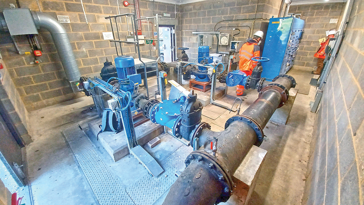
Inside the Sindlesham WBS before the upgrade – Courtesy of Ward & Burke
Replacing the existing assets raises major risks around the operation of the pumping station and the direct impact any downtime or failures would have on the network.
The solution therefore needed to allow for the required redundancy for the critical assets and overall system. The result of which ensured that power supply and pump operation had sufficient redundancy, and automatic control in the case of any failures.
Maintaining visibility and feedback of the site on regional site SCADA for both existing and new assets added another layer of protection for site operations should any failures occur, meaning they could be addressed promptly.
Sindlesham WBS: Supply chain – key participants
- Main designer & contractor: Ward & Burke
- GPR & topo survey: Brunel Surveys Ltd
- Hydraulic analysis: Hydraulic Analysis Limited
- HAZOP & ALM studies: Streamflow Engineering
- Electrical installation: LDC Electrics
- MCC & system integration: Bilfinger UK
- Kiosk: Morgan Marine Ltd
- Excavation supports: MGF Ltd
- Surge vessels: Quantum Engineering Developments Ltd
- Underpressure tapping & in-line valves: R2M Limited
- Pipework: Saint Gobain PAM UK
- Pipework: Electrosteel Castings (UK) Ltd
- Stainless steel pipework: ABC Stainless Ltd
- Pipework fittings: Frazer Utilities
- Pipework disinfection: WSM Associates Ltd
- Testing equipment: VP Stopper Specialist (Groundforce)
- Lowara pumps: Xylem Water Solutions
- Valves: AVK UK Ltd
- Pressure & flow instruments: ABB
- Pressure switches: IFM Electronics
- Ventilation systems: Air Technology Systems
- Standby generator & fuel tank: DTGen
Temporary works
Works commenced late April 2025, with the installation of the temporary site backup generator. This allowed for the existing defunct diesel generator to be removed from the WBS building and the accompanying external fuel tank to be removed from the rear of the building.
These works freed up much-needed space in an already confined site for new equipment, without reducing the site’s redundancy with respect to power supply.
The construction sequence then centred around completing as much of the off-line works as possible, so that once pump changeover started, the site overall always had backup power and pumping capabilities. Civil works could now be undertaken which included ducting, drainage and slab works for the new kiosk, fuel tank and standby generator.
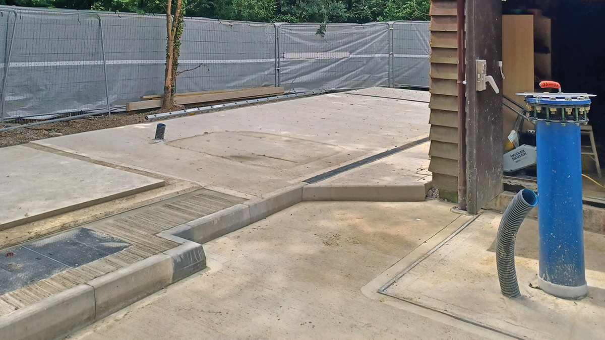
New generator & fuel tank slab – Courtesy of Ward & Burke
First shutdown
Full site shutdowns meant that all pumping was stopped for a short period of time. The first of these required a 90 minute shutdown to complete the necessary enabling works on the existing pipework and replace two 90° bends with tees on the suction side of the WBS.
This was required for:
- An external connection for the new suction surge vessel from Quantum Engineering Developments Ltd, and;
- An internal connection to install a new double acting air valve upstream of the pumps.
Completing these pieces of work together ensured that the surge vessel could later be connected and commissioned without disturbing supply to customers. Following these connections, the civils works to the southern and eastern sides of the WBS could be completed.
Underpressure tappings & in-line valves
Due to the limitations on site, shutdowns, and the availability of existing valves, underpressure tappings and in-line valves were used wherever possible, to ensure minimal disruption to the pumping operations and customers. One of these opportunities was for the discharge surge vessel connection.
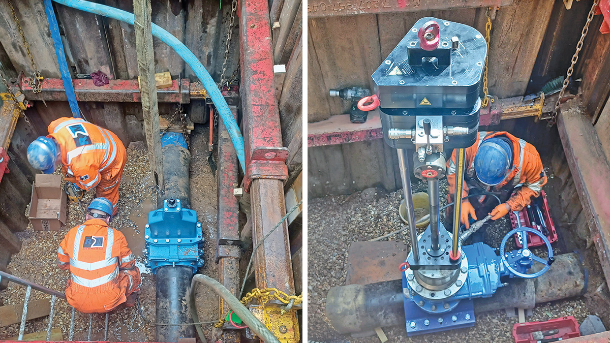
(left) Discharge surge vessel underpressure tapping and (right) WBS discharge in-line valve – Courtesy of Ward & Burke
This connection was completed via underpressure tapping by R2M Limited to provide a DN250 connection off the existing DN300 DI rising main. Further downstream on the same line, an in-line valve was installed as there was no existing isolation valve on the 4.2km rising between Sindlesham WBS and Bearwood SR. This valve would be used to isolate the discharge side of Sindlesham WBS for the second shutdown.
Second shutdown
The second full site shutdown was required to provide the discharge connection for Pump No. 2 within the WBS. Again, opportunities to reduce shutdowns as far as practicable was priority and so works were also planned to coordinate the removal of a non-return valve on the same line, but 4km away at the Bearwood SR site.
Hydraulic analysis indicated that an existing non-return valve on the rising main entering Bearwood was a major contributor to potential surge events associated with the operation at Sindlesham. The valve posed such a risk that the analysis recommended its removal.
As these works would also require shutdown of Sindlesham WBS, they were scheduled to be undertaken together during the 105 minute shutdown.
A temporary air valve was fitted to the new connection to ensure adequate air removal during refilling of the line and reverting the pumping station back to normal operation.
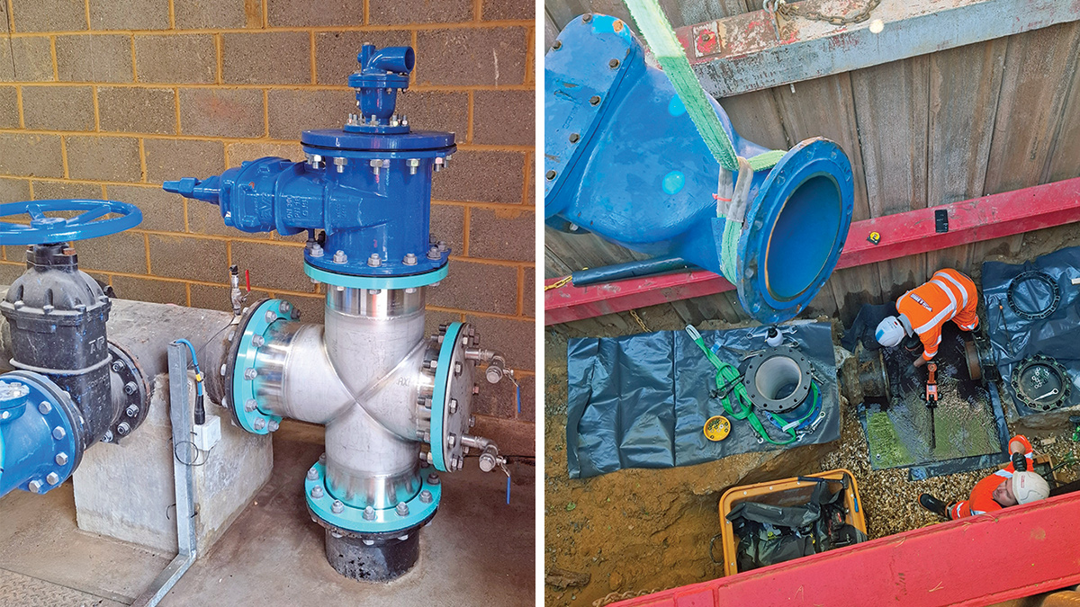
(left) Pump No. 2 discharge connection and (right) removal of the NRV at Bearwood – Courtesy of Ward & Burke
In-building & external works
Works within the building continued in parallel to external works with installation of steelwork to support the existing precast slab ceiling that previously enclosed the generator room. Removal of this precast ceiling was identified in the project’s Design Risk Assessment as a high-risk activity and as such, solutions were sought to remove the risks associated with its removal, while still allowing the block wall dividing the building to be removed.
Once the block wall was removed, the new MCC could be installed, behind the existing MCC, in preparation of the pump installation.
External to the building, the generator and fuel tank were being installed, followed by the kiosk and the surge vessels.
Final shutdown
The final site shutdown could be scheduled, and this was to install a new valve on the existing discharge manifold. The installation of this valve ensured that the first booster pump could be replaced off-line, removing the risk of unplanned pumping outages and ensuring undisturbed supply for customers. The shutdown lasted approximately 60 minutes.
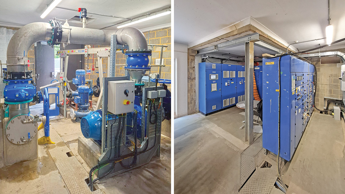
(left) First new pump installed with the standby provisions in the background and (right) MCC installation – Courtesy of Ward & Burke
Pump No. 1 replacement
Works then continued to remove Pump No. 1 and replace with the new 55kW Lowara end suction unit from Xylem Water Solutions.
During this period, the site was operating without a standby pump. Provisions were made for the removed pump to be kept on site, adjacent the existing operating unit and beneath temporary lifting equipment. This would allow site operations and/or Ward & Burke to act promptly should an issue arise with the duty pump, when the first new pump was being commissioned and put into service.
Proving period
At this juncture, the site was ready to begin operating on the new pump and begin a 14-day proving period. This new pump was powered and controlled by the new MCC, with backup power provided by the new standby generator. Pump signals were temporarily hard-wired to the telemetry outstation to ensure site operations and regional SCADA had remote visibility of the new pump operation status.
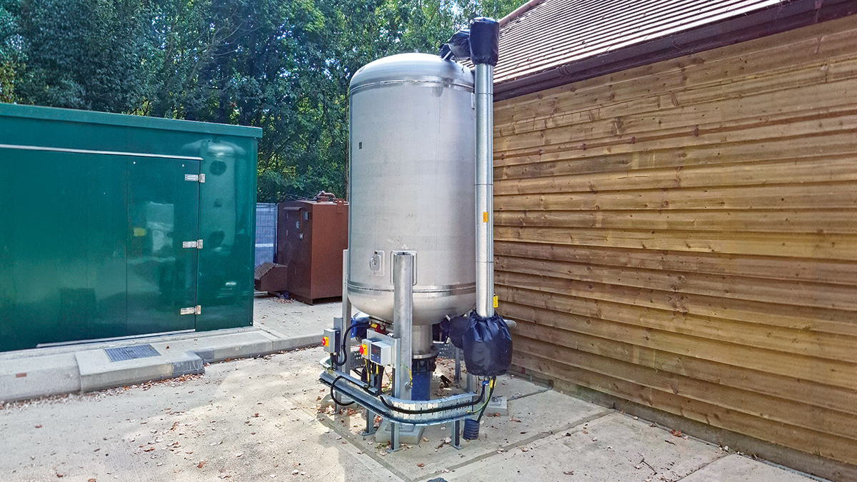
Surge vessel – Courtesy of Ward & Burke
A hard-wired duty signal was also installed between the new MCC PLC, and the existing MCC control logic, which replaced the old pump input signals. This meant that if the new pump tripped, or failed in any capacity, the existing MCC would be provided an input and automatically start the existing pump. In other words, the site was running on two separate pumps, power and control systems during this period, working in a duty/standby arrangement, ensuring complete redundancy of the new system.
Following successful completion of this proving period, the existing pump and MCC could be removed and close out works could begin.
A partition wall was erected between the new MCC and the pumps to create an MCC room, separate to the pump room. The new ventilation system was installed and commissioned, alongside completion of all electrical installation works. Finally, a new non-slip floor finish was applied, walls and ceilings painted and new floor trench covers were installed to complete the project.
Conclusion
Handover was completed in December 2025, marking the end of the first phase in the wider contract, ensuring sufficient flows for future demand are fed to Bearwood Service Reservoir. The second phase of works requires a full upgrade of Bearwood WBS, to ensure that the future flow demands can be delivered directly to customers in the growing Arborfield area.
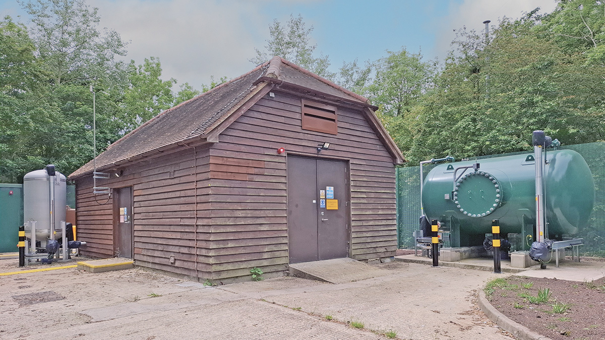
Sindlesham Water Booster Station - Courtesy of Ward & Burke