
Wanlip STW (2026)
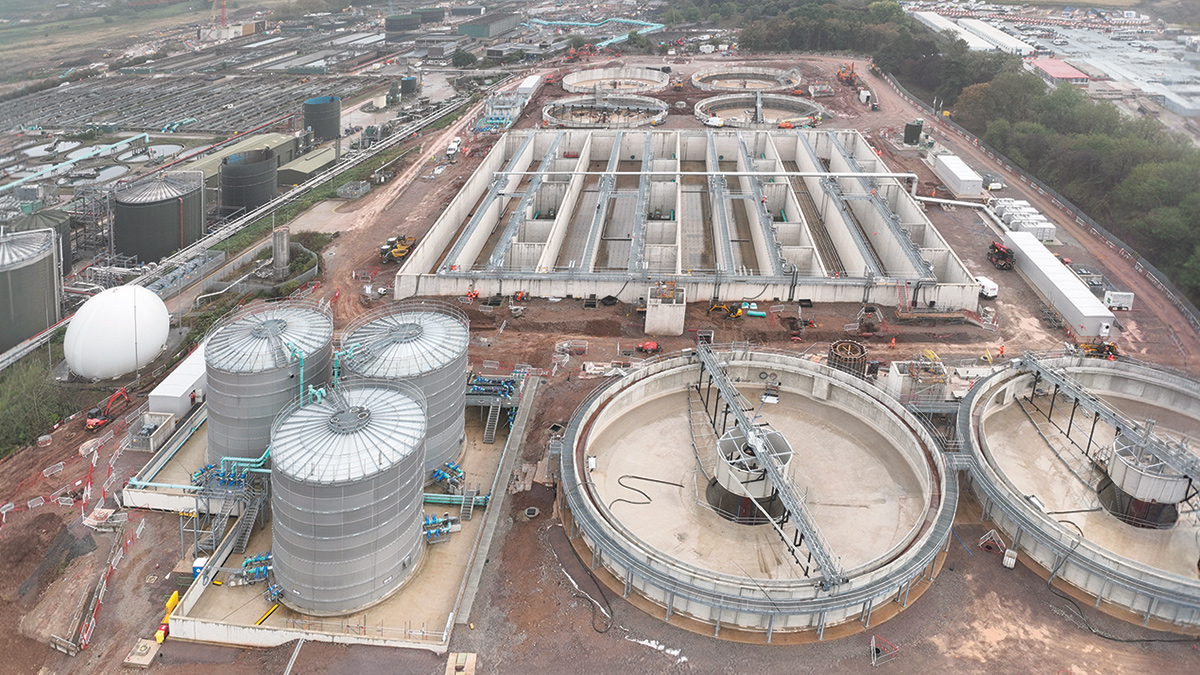
Wanlip STW site overview: (foreground) post-digested sludge storage tanks and primary settlement tanks, (middle) the activated sludge plant, and (background) the final settlement tanks - Courtesy of MWH Treatment
Wanlip STW is Severn Trent’s third-largest works, serving a population equivalent of 900,000 in the Leicester area. The existing works consists of two sewage treatment streams: Stream 1, a 1960s plant, and Stream 2, a 1990s plant extension. The site also has a bioresources digestion plant. Between 2005 and 2009 (AMP3), the existing Streams 1 and 2 were converted to biological nutrient removal, and in 2014 (AMP5), both the Stream 1 and Stream 2 inlet works were replaced with a single works to provide improved preliminary treatment to all flows arriving at the site.
Project background & drivers
The AMP8 Wanlip STW Green Recovery Project is one of several initiatives being delivered by Severn Trent to accelerate environmental improvements and enhance river water quality through increased phosphorus removal. The scheme will also address treatment capacity constraints caused by historic growth within the catchment, reducing the risk of future discharge permit breaches while accommodating significant forecast population and development growth. The project is required to deliver compliance with revised Environment Agency permit requirements for:
- DWF/FFT consent compliance by 30 December 2026.
- Phosphorus consent compliance by 30 December 2027.
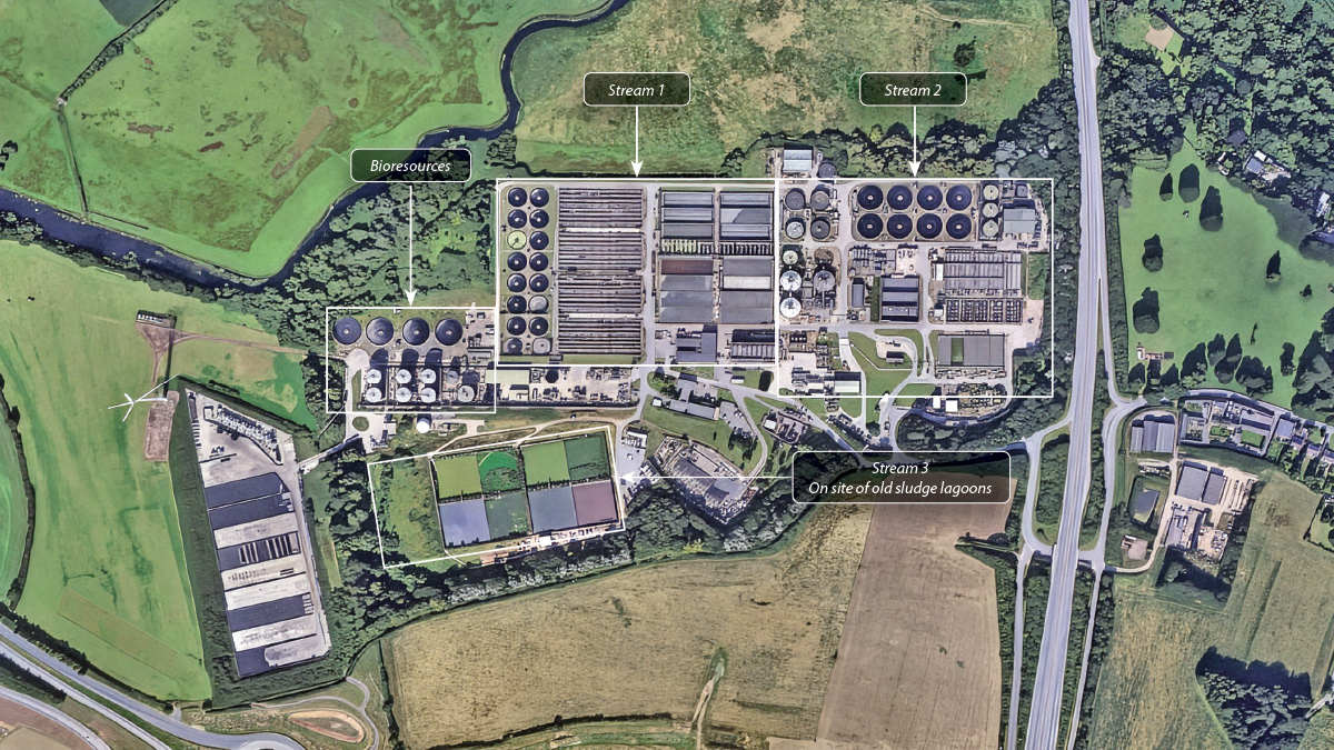
Google Maps image of Wanlip STW pre-AMP8 construction – Courtesy of MWH Treatment
Early Contractor Involvement (ECI)
MWH Treatment was appointed under an Early Contractor Involvement (ECI) model to review the consultant-developed solution, programme and cost estimates. The review focused on buildability, construction sequencing, process certainty and programme maturity. The £590,000 ECI commission commenced on 4 January 2024 and was completed on 4 March 2024.
The original proposal involved phased refurbishment of the existing Streams 1 and 2 treatment facilities, supplemented by tertiary filtration and phosphorus dosing, delivered through a single-contractor model.
However, MWH Treatment’s review concluded that the proposed approach would miss the required compliance dates by approximately 18 months due to the time required to safely isolate, drain and refurbish the operational assets. In addition, affordability assessments indicated that the overall scheme cost could rise from the original £240m estimate to around £300m.
As part of the review, MWH Treatment’s Advanced Solutions Group developed an alternative concept involving the construction of a new offline Stream 3 and associated interconnecting pipe gallery. The option demonstrated potential savings of approximately £43m while also delivering a programme benefit of around 12 months, enabling Severn Trent to achieve both its regulatory obligations and affordability targets.
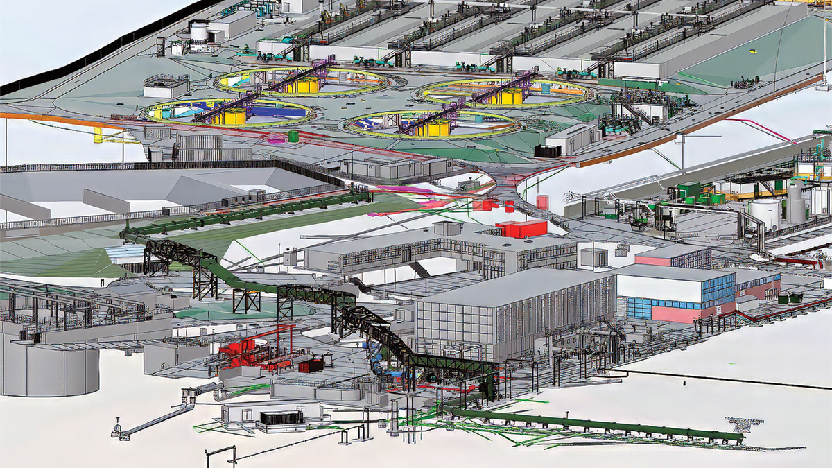
3D model of the interconnecting pipe bridges/galleries, avoiding services and keeping operational works access – Courtesy of MWH Treatment
Second ECI Phase
Working collaboratively with Severn Trent, MWH Treatment further developed the alternative solution and explored opportunities to split delivery responsibilities across framework partners to balance workload, secure long-term resources and strengthen delivery resilience across the region.
These recommendations were adopted, leading to a further £5.4m ECI award under NEC Option E. Running between August and December 2024, this phase focused on developing the alternative outline design while progressing enabling works. It also enabled emptying partially redundant lagoons ahead of demolition.
The revised solution centred on constructing a new treatment process stream, Stream 3, capable of treating flows of up to 900 l/s plus returns.
By locating the new assets within the footprint of partially redundant sludge lagoons, the majority of the works could be delivered offline, significantly reducing operational risks and programme constraints associated with modifying the existing treatment streams.
Lagoon emptying
The lagoon emptying was a complex operation. Of the eight lagoons, two were in use by Severn Trent’s Bio-operations team to buffer digested sludge from their bioresources plant prior to centrifuging.
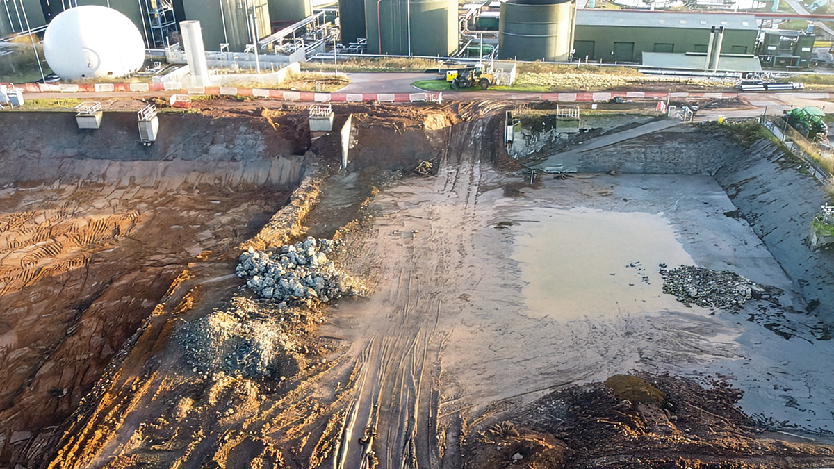
Lagoon emptying and demolition – Courtesy of MWH Treatment
The sludge in the remaining six lagoons was of unknown origin and make up and had to be fully tested and analysed. The sludge was confirmed as non-Biosolids Assurance Scheme (BAS) compliant, meaning it could not follow Severn Trent’s normal disposal route to land.
Vegetation was removed from the lagoons and the sludge liquors in the lagoons were treated through a temporary screen, grit removal and centrifuges to enable the sludge to be separated from the liquors.
- Sludge disposal: Multiple disposal routes were considered, including recycling and processing, but ultimately the sludge had to go to landfill because all other options were deemed unviable. The sludge was taken to numerous landfills across the UK, including sites as far away as Liverpool.
- Liquor treatment: The sludge liquors were extremely high in ammonia loads and could not be treated in the Wanlip Process streams. A number of other Severn Trent sewage treatment sites were identified for liquor disposal, including those at Minworth, Stoke Bardolph and Finham.
By Christmas 2025, the existing lagoons were emptied, enabling a further 70,000m3 of material to be excavated from the lagoon bases to create the formation for the new activated sludge plant (ASP) and final settlement tanks (FSTs).
As well as emptying the six redundant lagoons, MWH Treatment had to provide a new alternate sludge buffering plant to enable the two remaining bioresources lagoons to be emptied and demolished. This was provided in the form of a new post-digested sludge storage tank system. (PDSS). These new tanks had to be constructed and commissioned early in the process to facilitate the removal of the two bio-operations lagoons.
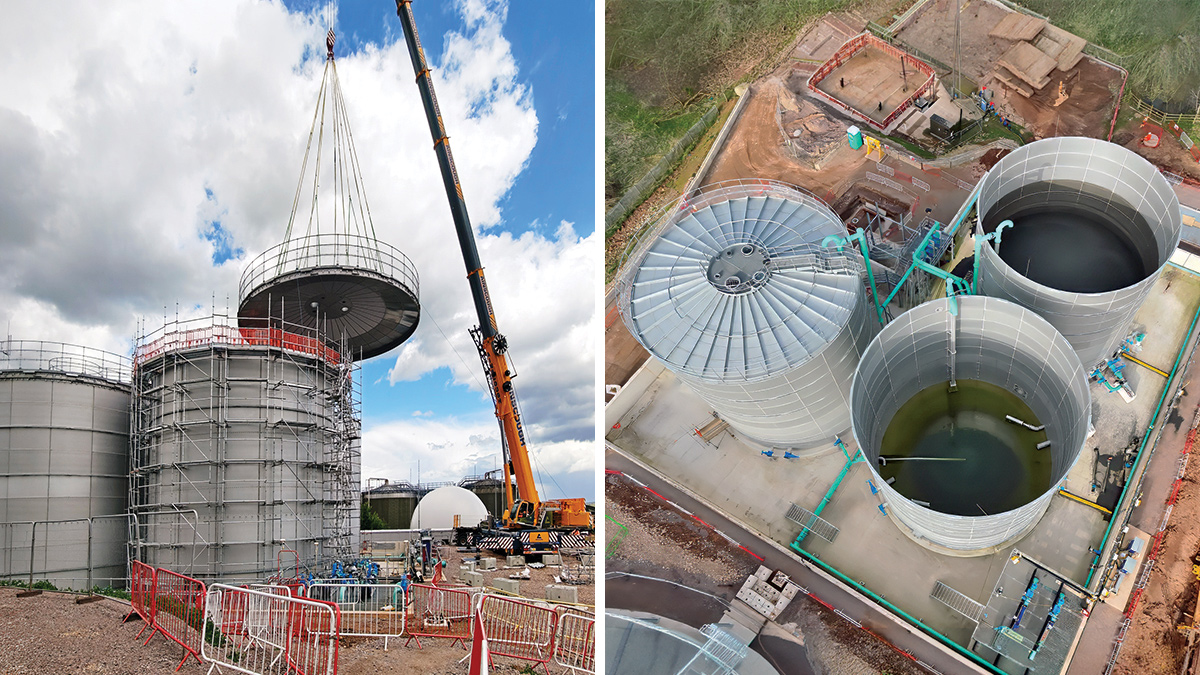
The new PDSS tank installation. Each tank holds 2,000m3 of digested sludge – Courtesy of MWH Treatment
Sectional completion 1 & contract completion
The MWH Treatment main contract has two completion dates:
- Sectional Completion 1: Readying the new Stream 3 plant to accept 500 l/s: 30 December 2026.
- Contract Completion: To complete the whole of the works to treat 900 l/s plus returns: 30 December 2027.
Main project overview
The main works contract for MWH Treatment was awarded in March 2026 under an NEC Option C arrangement, with a value of approximately £131m. This was delivered alongside a separate £110m contract awarded to Kier for the remaining elements, bringing the total scheme value to around £240m. The contract awards reflected the collaborative approach established during the ECI phase, which defined the overall delivery strategy.
This case study focuses on the scope of works delivered by MWH Treatment.
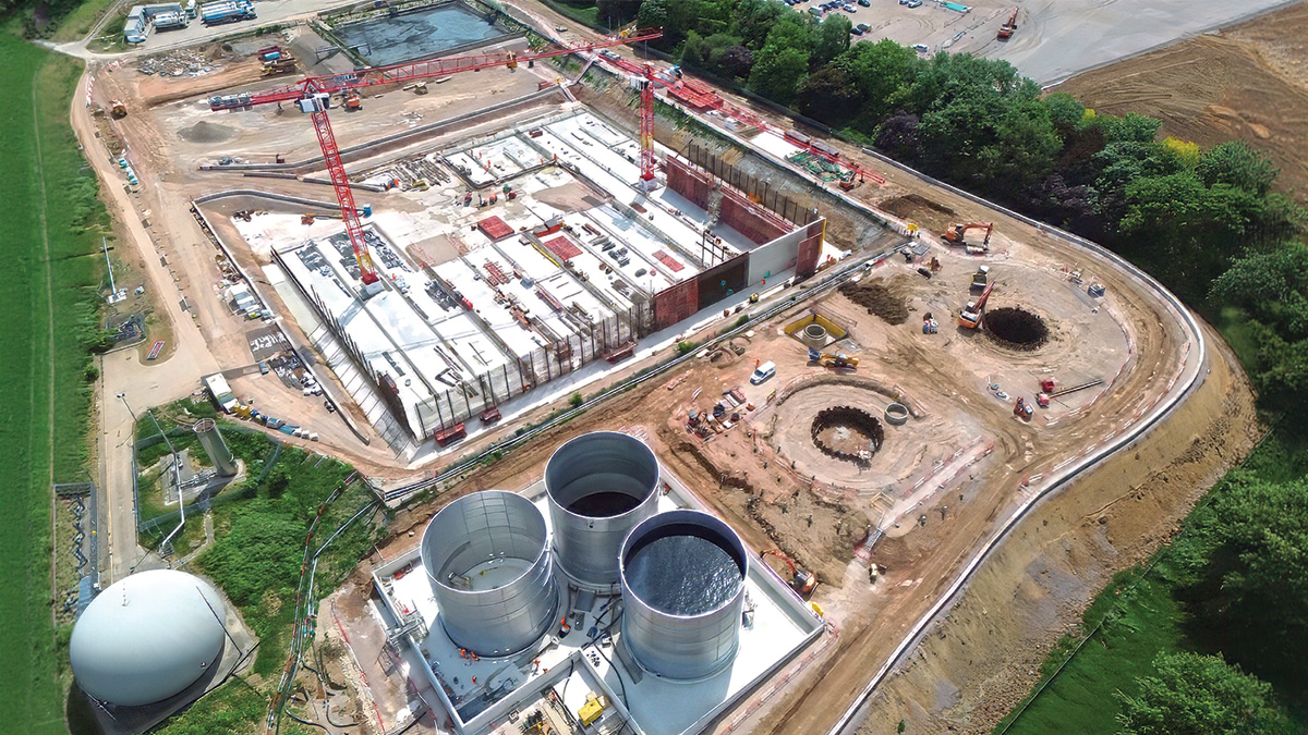
Start of ASP construction – Courtesy of MWH Treatment
Wanlip STW: Supply chain – key participants
- Client: Severn Trent
- Principal contractor & designer: MWH Treatment
- Ground investigations: RSK Geosciences
- Ecologist: Middlemarch Environmental Ltd
- Structural engineering (pipe gantry): Binnies
- Temporary cofferdam piling: Sheet Piling (UK) Ltd
- Piling contractor: Balfour Beatty Ground Engineering
- Civil sub-contractors: CR Civil Engineering
- Civil sub-contractors: Naylors
- Temporary works/shoring: National Trench Safety UK
- ASP FRC: STAM Construction Ltd
- ASP aeration system: Suprafilt Ltd
- ASP blowers: Sulzer Pumps Wastewater Ltd
- Precast concrete tanks: A-Consult Ltd
- PDSS tanks: Stortec Engineering Ltd
- Progressive cavity pumps (PDSS tanks): SEEPEX UK Ltd
- PST/FST bridges & aeration access: WGM Engineering Ltd
- Above-ground gantries & pipebridges: Industrial Engineering & Installation Services (IEIS)
- Pipework: Saint Gobain PAM UK
- RAS/SAS & ASP mechanical: Fluid Sealing & Engineering (FSE)
- PST access systems: Steelway
- Electrical installation: Elsym Installations
- MCCs: RSE Control Systems (Blackburn Starling)
- inDENSE™ Hydrocyclone: SUEZ Group
- Pumps (Inlet PS & RAS/SAS PS): Xylem Water Solutions
- Valves: Cotswold Valves Ltd
- Primary sludge RAM pumps: EMS Industries Ltd
- Lifting equipment: T Allen Engineering Services Ltd
- Lifting operations: Dewsbury & Proud
- Lifting operations: King Lifting
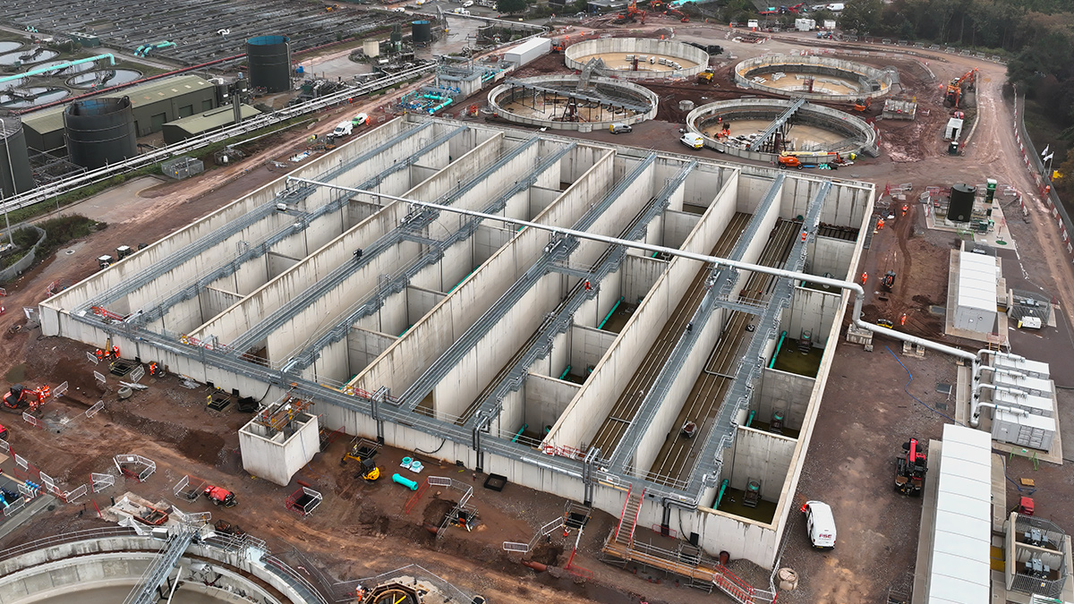
Activated sludge plant and final settlement tanks construction progress – Courtesy of MWH Treatment
Scope of works
For the delivery of the new process Stream 3, the design required the construction of:
- Three new piled 2000m3 post-digested sludge storage tanks for an Industrial Emissions Directive (IED) compliant solution.
- Two new 37m diameter piled primary settlement tanks.
- A new 50,000m3 ASP arranged in four triple-pass lanes with enhanced biological phosphorus removal (EBPR) University of Cape Town configuration.
- Four new 37m diameter final settlement tanks.
- RAS/SAS pumping station with a hydrocyclone SAS recovery system.
- New feed pumping station capable of passing flows of up to 1500 l/s.
- Ancillary pumping stations and distribution chambers.
Ground preparation
Extensive ground investigations and engineering assessments were undertaken to optimise the foundation design and minimise the requirement for piling across the site. As a result of these studies, the treatment process layout was rotated by 180°, relocating the two PSTs and the PDSS tanks to the area of the site with poorer ground conditions. This strategic redesign enabled the activated sludge plant (ASP) and FSTs to be constructed without piling, delivering significant savings in both programme duration and project cost.
Where piling was required, the PSTs and PDSS tanks were founded on precast driven piles ranging from 8m to 17m in length.
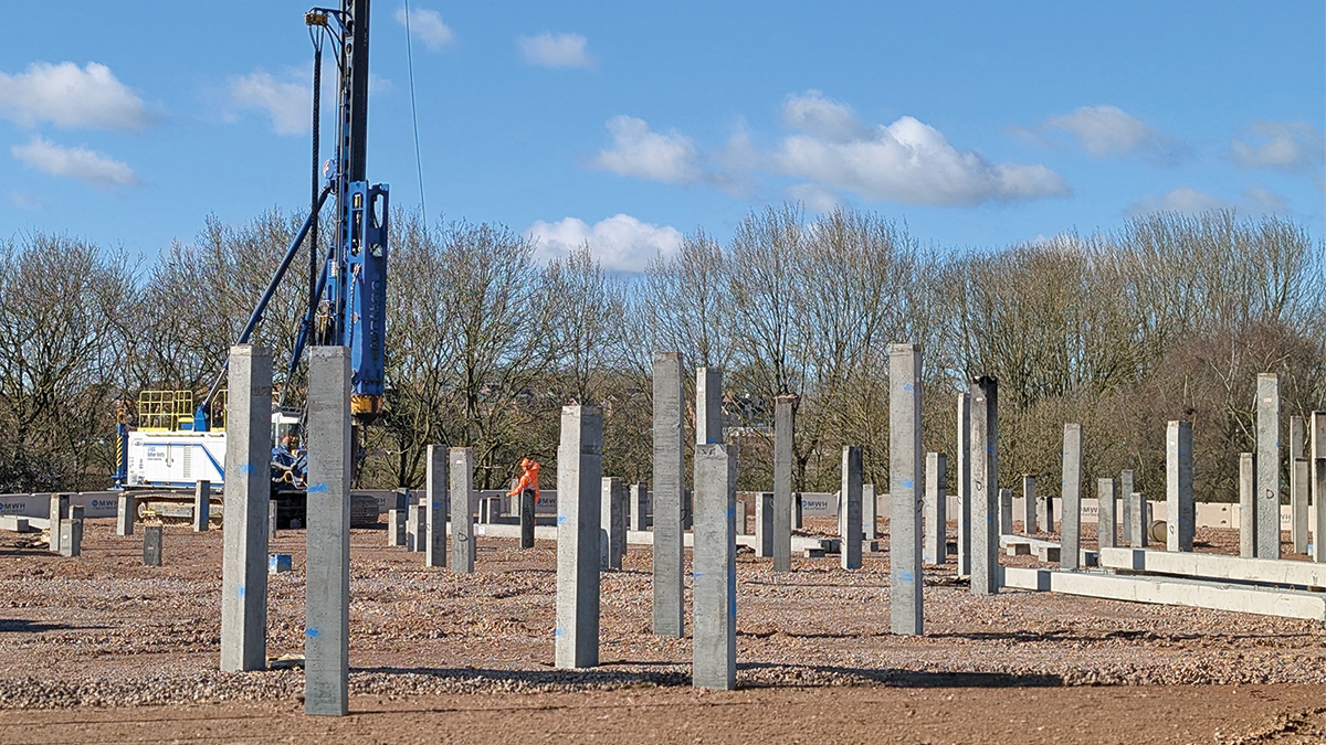
Piling works for the settlement tanks – Courtesy of MWH Treatment
To prepare the site for construction, cementitious stabilisation techniques were employed during the formation of piling mats and working platforms. By stabilising the excavated material in situ and placing it in engineered layers, the project team significantly reduced the volume of unsuitable ground requiring removal and replacement with imported structural fill. This approach generated substantial cost and programme benefits and delivered a considerable reduction in embodied carbon by minimising material transport and importation.
Post-digested sludge storage tanks
The post-digested sludge tank installation comprises three 2,000m3 high-grade stainless steel tanks from Stortec Engineering Ltd, complete with associated pipework, mixers, access steelwork, and progressive cavity pumps.
A reinforced concrete bund has been constructed to provide containment equivalent to 110% of the volume of a single tank in the unlikely event of a failure. The facility has been designed to achieve full Industrial Emissions Directive (IED) compliance for land, water and air protection and includes a new MCC panel, lightning protection system, and integration with the existing gas management system.
Primary settlement tanks & final settlement tanks
The primary settlement tanks and final settlement tanks were designed as precast post-stressed solutions, as provided by A-Consult Ltd. This requires a traditional cast reinforced base slab and uses modular concrete panelled wall sections that are post-stressed using steel tendons following wall erection and alignment. Again, the precast DfMA solution to these tanks provides a cost-effective and speedy solution to the construction of circular tanks.
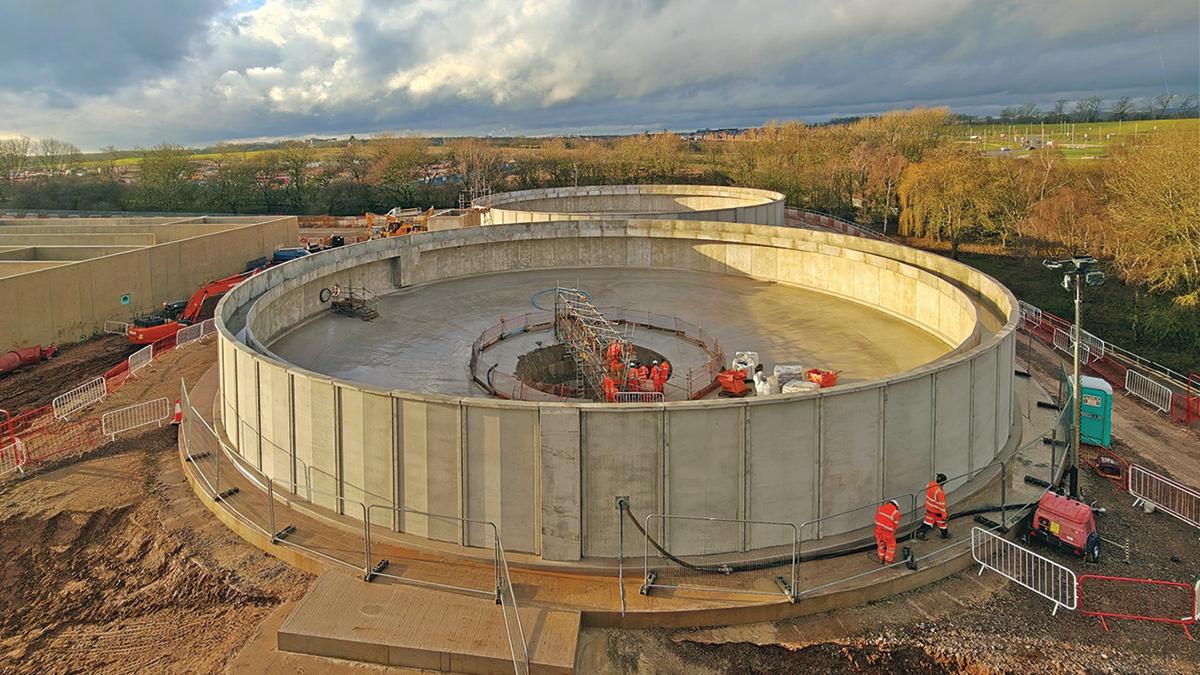
PST construction – Courtesy of MWH Treatment
Inlet pumping station & interconnecting pipe gallery
The new interconnecting pipe bridge network comprises approximately 500m of elevated pipework supported on 5m-high steel gantries. The structure carries a 1,200mm diameter feed pipe and a 1,400mm diameter return pipe, providing the necessary hydraulic connection between the new feed pumping station and the PST distribution chamber, before returning flows to the TSR distribution system being delivered under a separate contract.
Activated sludge plant
During design development, the ASP tank was considered for constructability and carbon savings. An early decision was to use two tower cranes for tank construction. These were designed such that the crane bases were integrated into the ASP base structure, allowing the cranes to be erected and demobilised easily without impacting the tank base construction.
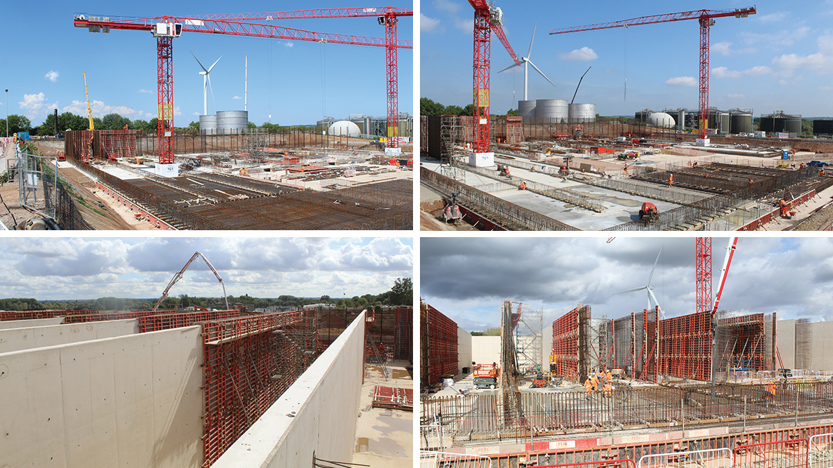
ASP construction – Courtesy of MWH Treatment
Tapered walls were utilised between cells and for the outer walls, resulting in savings in reinforcement and concrete and associated carbon. Temporary king-posts were designed in conjunction with the FRC contractor, STAM Construction Ltd, to support the wall reinforcement before shutters were installed. For such a large concrete tank, these savings in materials and carbon offset result in a significant benefit to the contract.
Feed pumping station
The new feed pumping station connects to the existing inlet works and balances flows across the two structures. This enables the new Stream 3 feed pumping station to take up to a pre-defined set point of flows (up to 900l/s plus returns) to be treated at the new Stream 3 works. These flows are conveyed to the new works via an overhead gantry which carries both the feed rising main from the Stream 3 pumping station and the return gravity main after treatment.
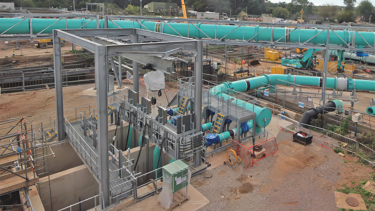
Feed pumping station – Courtesy of MWH Treatment
Return & surplus activated sludge (RAS/SAS) pumping station
The RAS/SAS pumping station has been designed to provide a maximum RAS flow of 900 l/s and a maximum SAS flow of 44 l/s by incorporating an advanced inDENSE™ hydrocyclone system. The facility includes three RAS pumps configured duty/assist/standby, two SAS pumps configured duty/standby, and all associated pipework, valves, access steelwork, and flow measurement equipment. The installation includes a duty hydrocyclone system comprising seven cyclones mounted on two skids to support sludge densification and process optimisation.
The pumping station is housed in a reinforced concrete wet well that accommodates the pumps, underground pipework, flow meter chambers, associated slabs, and footpaths. The installation includes a dedicated MCC panel, kiosk, and all associated electrical, instrumentation, control, and automation (EICA) systems.
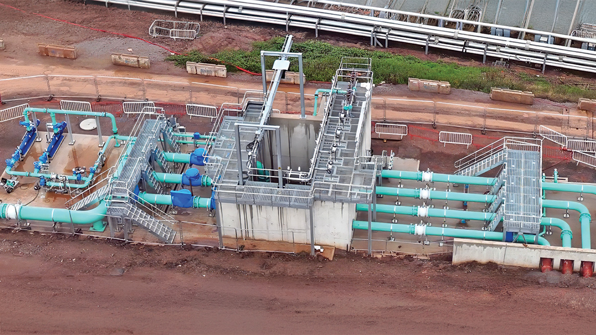
RAS/SAS pumping station – Courtesy of MWH Treatment
Ancillary pumping stations & distribution chambers
The ancillary pumping stations and distribution chambers provide the supporting infrastructure required for reliable sludge handling, chemical dosing, drainage, and process operation across the site.
The installation includes three primary sludge screens arranged in a duty/assist/standby configuration, along with a primary sludge transfer pumping station with two duty/assist pumps capable of transferring flows of up to 55 l/s. A dedicated washwater system delivers 4 l/s at 3 bar pressure, while a separate drainage pumping station incorporates two duty/standby pumps to manage site drainage requirements.
Primary sedimentation tank desludging is achieved using a dedicated RAM pump for each PST, with two units installed in total. The ancillary facilities include a ferric sulphate dosing skid with 45m3 of storage capacity and two duty/standby dosing pumps to support process performance and treatment compliance.
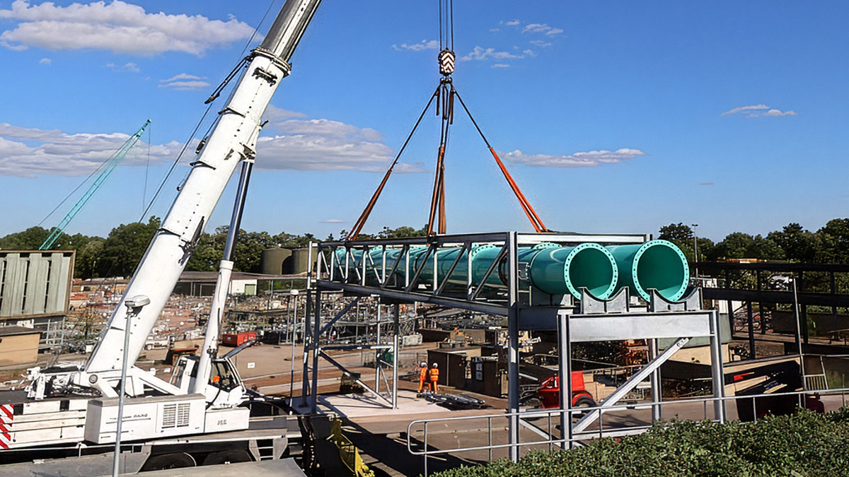
Installation of a section of the above-ground pipe bridge installed in sections following off-site manufacturing – Courtesy of MWH Treatment
Progress/current status
Progress on the project continues at pace, with the primary focus on enabling seeding of the activated sludge plant by mid-December. The delivery team is working diligently to recover programme delays, deploying additional resources where necessary to meet the demands of a highly challenging schedule.
At the time of writing (September 2026), the civil engineering works are approximately 90% complete, with mechanical installation 75% complete and electrical installation 60% complete.
Commissioning activities are scheduled to continue throughout December 2026 and into January 2027, while the team remains focused on meeting the regulatory requirement to treat 500 l/s through Stream 3 by 30 December 2026.
Following this milestone, work will focus on final commissioning, road construction, landscaping, and site finishing.
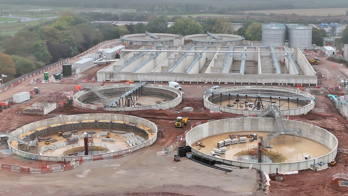
FST construction - Courtesy of MWH Treatment